2004 SUZUKI SWIFT Brake light diagram
[x] Cancel search: Brake light diagramPage 687 of 1496

Downloaded from www.Manualslib.com manuals search engine Automatic Transmission/Transaxle: 5A-43
Transmission Warning Light Circuit Check – Light Does Not Come “ON” at Ignition Switch ONS7RS0B5104021
Troubleshooting
Transmission Warning Light Circuit Check – Light Remains “ON” at Ignition Switch ONS7RS0B5104022
TroubleshootingStep Action Yes No
1 Was “A/T System Check” performed? Go to Step 2. Go to “A/T System
Check”.
2 Check DTC
Is DTC P0705, P0707, P0712, P0713, P0717, P0722,
P0787, P0788, P0961, P0962, P0963, P0973, P0974,
P0976, P0977, P1702, P1703, P1774, P1777, P2762,
P2763 and/or P2764 detected? Go to applicable DTC
diag. flow.
Go to Step 3.
3 Brake light switch signal inspection
1) With ignition switch turned ON, check voltage between
terminal “C35-20” of ECM connector and ground.
Brake light switch signal specification
Brake pedal is released: 0 – 1 V
Brake pedal is depressed: 8 – 14 V
Is result as specified? Substitute a known-
good TCM and recheck.
Mis-adjusted brake light
switch or faulty brake
light switch.
Step
Action YesNo
1 Combination meter power supply check
1) Turn ignition switch ON.
Does other indicator / warnin g lights in combination meter
comes ON? Go to Step 2.
Repair combination
meter power supply
circuit referring to “C-1
Combination Meter
Circuit Diagram (Meter)
in Section 9A”.
2 TCM power and ground circuit check
1) Check referring to “TCM Power and Ground Circuit
Check”.
Is it in good condition? Go to Step 3.
Repair or replace.
3 DTC check
1) Check DTC referring to “DTC Check”.
Is there DTC P1774? Go to applicable DTC
diag. flow.
Go to Step 4.
4 Combination meter function check
1) Turn ignition switch ON.
Does A/T selector position in dicator show correct select
lever position? Replace combination
meter.
Substitute a known-
good TCM and recheck.
Step
Action YesNo
1 Diagnostic Trouble Code (DTC) Check
1) Check DTC referring to “DTC Check”.
Is there any DTC(s)? Perform DTC Flow to
repair and retry.
Substitute a known-
good TCM and recheck.
If OK, substitute a
known-good
combination meter and
recheck.
Page 1167 of 1496

Downloaded from www.Manualslib.com manuals search engine Table of Contents 9- i
9
Section 9
CONTENTS
Body, Cab and Accessories
Precautions ................................................. 9-1
Precautions............................................................. 9-1
Precautions on Body, Cab and Accessories ......... 9-1
Precautions for Body Service ................................ 9-1
Fastener Caution for Body Service ....................... 9-1
Wiring Systems............... ......................... 9A-1
Precautions........................................................... 9A-1
Cautions in Body Electrical System Servicing..... 9A-1
General Description ............................................. 9A-1 Abbreviations ...................................................... 9A-1
Wire / Connector Color Sy mbols ......................... 9A-1
Symbols and Marks ............................................ 9A-2
How to Read Connector Layout Diagram ........... 9A-4
How to Read Connector Codes and Terminal Nos.................................................................... 9A-5
How to Read Ground Point ................................. 9A-7
How to Read Power Supply Diagram.................. 9A-8
How to Read System Circuit Diagram................. 9A-8
Connector Layout Diagram . .............................. 9A-10
Connector Layout Diagram ............................... 9A-10
Engine Compartment .......... .............................. 9A-10
Instrument Panel ............................................... 9A-16
Door, Roof......................................................... 9A-20
Floor .................................................................. 9A-23
Rear .................................................................. 9A-29
Ground Point ...................................................... 9A-30 Ground (earth) Point ......................................... 9A-30
Power Supply Diagram ........ .............................. 9A-31
Power Supply Diagram ....... .............................. 9A-31
Fuses and the Protected Parts ......................... 9A-33
Fuses in Main Fuse Box (RHD) ........................ 9A-33
Fuses in Main Fuse Box (LHD) ......................... 9A-33
Individual Circuit Fuse Box No. 1 ...................... 9A-34
Individual Circuit Fuse Box No. 2 (In J/B) ......... 9A-35
Junction Block (J/B) Connector / Fuse Layout .. 9A-37
Junction Block Inner Circuit (Overview) ............ 9A-38
Junction Block Inner Circuit (Detail) .................. 9A-40
System Circuit Diagram... .................................. 9A-45
System Circuit Diagram .. .................................. 9A-45
A-1 Cranking System Circ uit Diagram .............. 9A-46
A-2 Charging System Circu it Diagram .............. 9A-47
A-3 Ignition System Circu it Diagram ................. 9A-48
A-4 Cooling System Circuit Diagram................. 9A-49 A-5 Engine and A/C Control System Circuit
Diagram........................................................... 9A-50
A-6 A/T Control System Circuit Diagram........... 9A-55
A-7 Immobilizer System Circuit Diagram .......... 9A-57
A-8 Body Control System Circuit Diagram ........ 9A-58
B-1 Windshield Wiper and Washer Circuit Diagram........................................................... 9A-62
B-2 Rear Wiper and Washer Circuit Diagram ... 9A-63
B-3 Rear Defogger Circuit Diagram .................. 9A-64
B-4 Power Window Circuit Diagram .................. 9A-65
B-5 Power Door Lock Circu it Diagram .............. 9A-67
B-6 Power Mirror Circuit Diagram ..................... 9A-69
B-7 Horn Circuit Diagram .................................. 9A-70
B-8 Seat Heater Circuit Diagram....................... 9A-71
B-9 Keyless Start System Circuit Diagram........ 9A-72
C-1 Combination Mete r Circuit Diagram
(Meter)............................................................. 9A-73
C-2 Combination Mete r Circuit Diagram
(Indicator) ........................................................ 9A-74
C-3 Combination Mete r Circuit Diagram
(Warning Light)................................................ 9A-75
D-1 Headlight System Circuit Diagram ............. 9A-77
D-2 Position, Tail and Licence Plate Light System Circuit Diagram .................................. 9A-79
D-3 Front Fog Light System Circuit Diagram .... 9A-80
D-4 Illumination Light System Circuit Diagram .. 9A-81
D-5 Interior Light System Circuit Diagram......... 9A-82
D-6 Turn Signal and Hazard Warning Light System Circuit Diagram .................................. 9A-83
D-7 Brake Light System Circuit Diagram .......... 9A-85
D-8 Back-Up Light System Circuit Diagram ...... 9A-86
D-9 Headlight Beam Leveling System Circuit Diagram........................................................... 9A-87
D-10 Rear Fog Light Circuit Diagram ................ 9A-88
E-1 Heater System Circuit Diagram .................. 9A-89
E-2 Auto A/C System Circuit Diagram .............. 9A-91
F-1 Air-Bag System Circuit Diagram ................. 9A-93
F-2 Anti-Lock Brake System Circuit Diagram.... 9A-95
F-3 Electronic Stab ility Program System
Circuit Diagram .................. ............................. 9A-97
F-4 Power Steering System Circuit Diagram .... 9A-99
G-1 Audio System Circuit Diagram ................. 9A-101
G-2 Multi Information Display / Accessory Socket System Circuit Diagram .................... 9A-102
List of Connector .............................................9A-103
Page 1168 of 1496

Downloaded from www.Manualslib.com manuals search engine 9-ii Table of Contents
List of Connectors ........................................... 9A-103
C Connector .................................................... 9A-103
D Connector (M16A engine) ........................... 9A-104
E Connector .................................................... 9A-104
G Connector .................................................... 9A-106
J Connector ..................................................... 9A-108
K Connector .................................................... 9A-109
L Connector..................................................... 9A-109
M Connector (SPORT model) ......................... 9A-111
O Connector .................................................... 9A-111
R Connector .................................................... 9A-111
Lighting Systems .................................... 9B-1
Component Location ........... ................................9B-1
Lighting System Component s Location............... 9B-1
Interior Light System Location............................. 9B-2
Diagnostic Information and Procedures ............ 9B-2 Headlight Symptom Diagnosis ............................ 9B-2
Headlight Leveling System Symptom Diagnosis (If Equipped) ..................................... 9B-2
Turn Signal and Hazard Warning Light Symptom Diagnosis .......................................... 9B-3
Clearance, Tail and License Plate Light Symptom Diagnosis .......................................... 9B-3
Back-Up Light Symptom Diagnosis..................... 9B-4
Brake Light Symptom Diagnosis ......................... 9B-4
Front Fog Light Symptom Diagnosis (If Equipped) .......................................................... 9B-4
Interior Light Symptom Diagnosis ....................... 9B-5
Repair Instructions ..............................................9B-5 Headlight Housing Removal and Installation ...... 9B-5
Headlight Bulb Replacemen t............................... 9B-6
Headlight Aiming Adjustment with Screen .......... 9B-6
Headlight Switch (in Lighting Switch) Removal and Installation ................................... 9B-8
Headlight Switch (in Lighting Switch) Inspection .......................................................... 9B-8
Hazard Warning Switch Removal and Installation ......................................................... 9B-8
Hazard Warning Switch Inspection ..................... 9B-9
Brake Light Switch Inspection ............................. 9B-9
Turn Signal Light Switch (in Lighting Switch) Removal and Installation ................................... 9B-9
Turn Signal Light Switch (in Lighting Switch) Inspection .......................................................... 9B-9
Turn Signal and Hazard Warning Relay Removal and Installation ................................... 9B-9
Turn Signal and Hazard Warning Relay Inspection ........................................................ 9B-10
License Light Removal and Installation............. 9B-10
Front Fog Light Removal and Installation (If Equipped) ........................................................ 9B-11
Front Fog Light Bulb Replacement (If Equipped) ........................................................ 9B-11
Front Fog Light Switch Inspection (If Equipped) ........................................................ 9B-11
Front Fog Light Relay Inspection (If Equipped) ........................................................ 9B-11
Front Fog Light Aiming Adjustment with Screen (If Equipped) ....................................... 9B-12 Headlight Leveling Switch Inspection (If
Equipped) ........................................................ 9B-13
Headlight Leveling Actuator Inspection (If Equipped) ........................................................ 9B-13
Instrumentation / Driver Info. / Horn ...... 9C-1
Precautions ...........................................................9C-1 Precautions in Diagnosing Troubles for Combination Meter ............................................9C-1
General Description .............................................9C-1 CAN Communication System Description...........9C-1
Auto Volume Co ntrol System Description (If
Equipped) ..........................................................9C-3
Schematic and Routing Diagram ........................9C-4 Combination Meter Circuit Diagram ....................9C-4
Component Location ............ ...............................9C-6
Audio System Component Location ....................9C-6
Diagnostic Information and Procedures ............9C-6 Speedometer and VSS Symp tom Diagnosis ......9C-6
Tachometer Symptom Diagnosis ........................9C-6
Engine Coolant Temperature (ECT) Meter Symptom Diagnosis ..........................................9C-7
Fuel Meter Symptom Diagnosis ..........................9C-7
Low Fuel Warning Light Symptom Diagnosis .....9C-7
Oil Pressure Warning Light Symptom Diagnosis ..........................................................9C-8
Brake and Parking Brake Warning Light Symptom Diagnosis ..........................................9C-8
Seat Belt Reminder Light Symptom Diagnosis (If Equipped)......................................................9C-8
A/T Shift Position Indicator Symptom Diagnosis (A/T Model).......................................9C-9
Charge Warning Light Sy mptom Diagnosis ........9C-9
Main Beam (High Beam) Indicator Symptom Diagnosis ..........................................................9C-9
Warning Buzzer Circuit Sy mptom Diagnosis ....9C-10
Cigarette Lighter Symptom Diagnosis (If Equipped) ........................................................9C-10
Horn Symptom Diagnosis .................................9C-10
Information Display Symptom Diagnosis (If Equipped) ........................................................9C-11
Clock Symptom Diagnosis (If Equipped)...........9C-12
Audio System Symptom Diagnosis (If Equipped) ........................................................9C-12
Remote Audio Control Switch Symptom Diagnosis (If Equipped) ...................................9C-13
Navigation Symptom Diagnosis (If Equipped)...9C-14
Repair Instructions ............ ................................9C-14
Ignition Switch Removal and Installation...........9C-14
Ignition Switch Inspection..................................9C-14
Combination Meter Removal and Installation ...9C-15
Fuel Level Sensor Removal and Installation .....9C-15
Fuel Level Sensor Inspection ............................9C-15
Oil Pressure Switch Remova l and Installation ..9C-15
Oil Pressure Switch Inspec tion .........................9C-16
Engine Coolant Temperature (ECT) Sensor Inspection ........................................................9C-16
Brake Fluid Level Switch Inspection .................9C-16
Parking Brake Switch Inspec tion.......................9C-16
Page 1216 of 1496

Downloaded from www.Manualslib.com manuals search engine 9A-45 Wiring Systems:
System Circuit Diagram
System Circuit DiagramS7RS0B910E001
Refer to “A-1 Cranking System Circuit Diagram”.
Refer to “A-2 Charging System Circuit Diagram”.
Refer to “A-3 Ignition System Circuit Diagram”.
Refer to “A-4 Cooling System Circuit Diagram”.
Refer to “A-5 Engine and A/C Control System Circuit Diagram”.
Refer to “A-6 A/T Control System Circuit Diagram”.
Refer to “A-7 Immobilizer System Circuit Diagram”.
Refer to “A-8 Body Control System Circuit Diagram”.
Refer to “B-1 Windshield Wiper and Washer Circuit Diagram”.
Refer to “B-2 Rear Wiper and Washer Circuit Diagram”.
Refer to “B-3 Rear Defogger Circuit Diagram”.
Refer to “B-4 Power Window Circuit Diagram”.
Refer to “B-5 Power Door Lock Circuit Diagram”.
Refer to “B-6 Power Mi rror Circuit Diagram”.
Refer to “B-7 Horn Circuit Diagram”.
Refer to “B-8 Seat Heater Circuit Diagram”.
Refer to “B-9 Keyless Star t System Circuit Diagram”.
Refer to “C-1 Combination Me ter Circuit Diagram (Meter)”.
Refer to “C-2 Combination Mete r Circuit Diagram (Indicator)”.
Refer to “C-3 Combination Meter Circuit Diagram (Warning Light)”.
Refer to “D-1 Headlight System Circuit Diagram”.
Refer to “D-2 Position, Tail and Licence Plate Light System Circuit Diagram”.
Refer to “D-3 Front Fog Light System Circuit Diagram”.
Refer to “D-4 Illumination Light System Circuit Diagram”.
Refer to “D-5 Interior Li ght System Circuit Diagram”.
Refer to “D-6 Turn Signal and Hazard Warning Light System Circuit Diagram”.
Refer to “D-7 Brake Light System Circuit Diagram”.
Refer to “D-8 Back-Up Light System Circuit Diagram”.
Refer to “D-9 Headlight Beam Leveling System Circuit Diagram”.
Refer to “D-10 Rear Fog Light Circuit Diagram”.
Refer to “E-1 Heater System Circuit Diagram”.
Refer to “E-2 Auto A/C System Circuit Diagram”.
Refer to “F-1 Air-Bag System Circuit Diagram”.
Refer to “F-2 Anti-Lock Brake System Circuit Diagram”.
Refer to “F-3 Electronic Stabilit y Program System Circuit Diagram”.
Refer to “F-4 Power Steeri ng System Circuit Diagram”.
Refer to “G-1 Audio Sy stem Circuit Diagram”.
Refer to “G-2 Multi Information Display / Accessory Socket System Circuit Diagram”.
Page 1226 of 1496

Downloaded from www.Manualslib.com manuals search engine 9A-55 Wiring Systems:
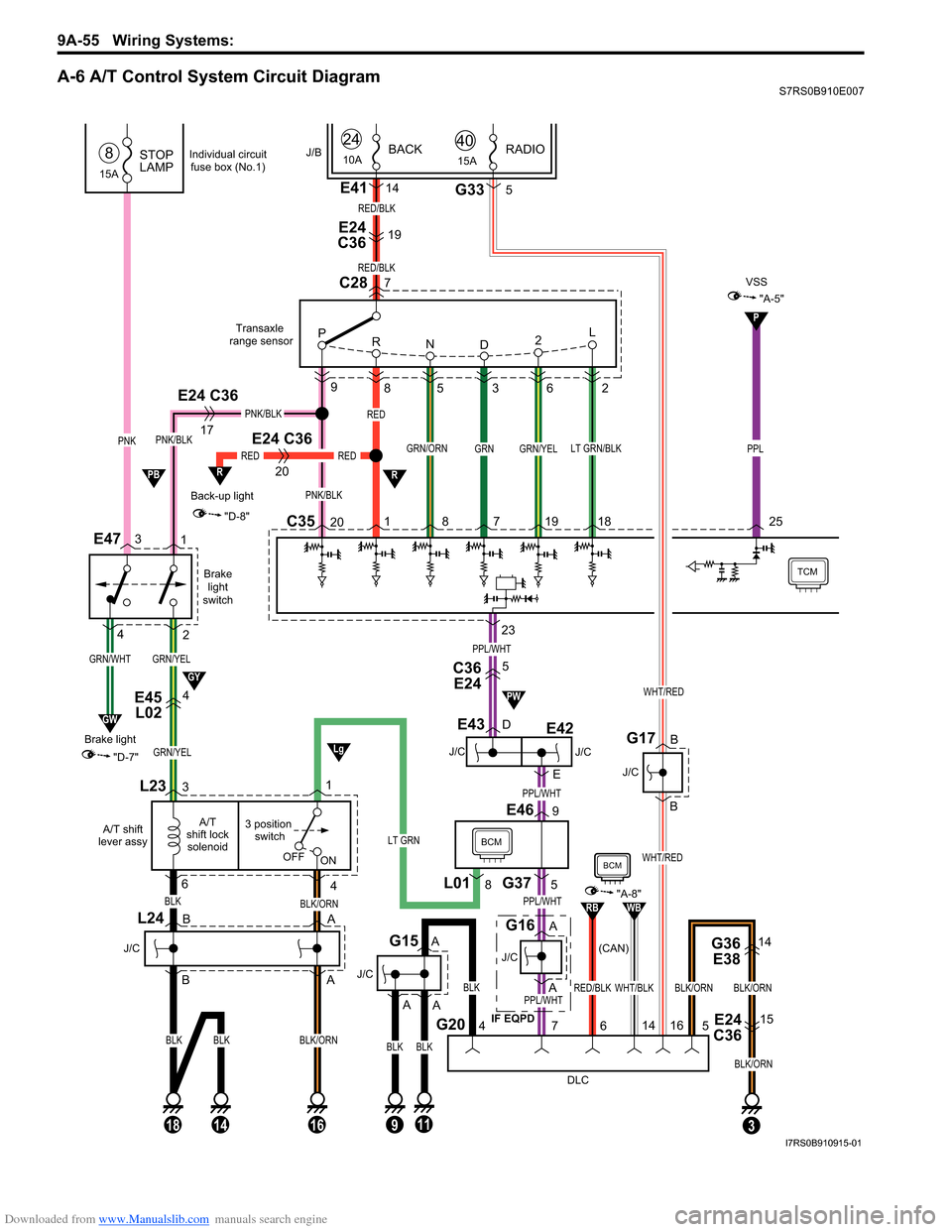
A-6 A/T Control System Circuit DiagramS7RS0B910E007
GRN/YEL
Brakelight
switch
E47
GRN/YEL
C3520 8 7 19 18
9
85 3 6 2
GRN/YEL
Back-up light
20
RED
"D-8"
R
Transaxle
range sensor
TCM
L23
4
3 position switch
A/T
shift lock solenoid
A/T shift
lever assy
BLK/ORN
16
OFF ON
RED
1
RED
BLK
PNK/BLK
GRN/ORNLT GRN/BLK
C28
P
R ND 2L
PNK/BLK
1
2
E24 C36
17
PNK/BLK
BLK
63
BLK/ORN
18
BLK
14
L24
J/C
E45
L024
J/C
E43
J/C (CAN)
G16
BCM
DLC
G207
G375
E469
4
BLK
BLKBLK
11
J/C
G15
3
G36
E3814
E24
C3615
BLK/ORNBLK/ORN
5
23
GRN
RED/BLK
7
E24
C3619
E4114
RED/BLK
PNK
15A
STOP
LAMP8
GRN/WHT
GW
"D-7"
Brake light
3
4
J/B
L018
1
24
10ABACK
A
A
B
B A
A
PPL/WHT
PPL/WHT
PPL/WHT
PPL/WHT
A
A
D
E
LT GRN
P
"A-5"
VSS
PPL
25
R
C36E245
Lg
GY
PB
PW
9
A
Individual circuit
fuse box (No.1)
WHT/BLKRED/BLK
RBWB
BCM
"A-8"
14
6
BLK/ORN
15ARADIO40
G335
WHT/RED
B
B
J/C
G17
WHT/RED
16
J/C
E42
IF EQPD
E24 C36
I7RS0B910915-01
Page 1246 of 1496

Downloaded from www.Manualslib.com manuals search engine 9A-75 Wiring Systems:
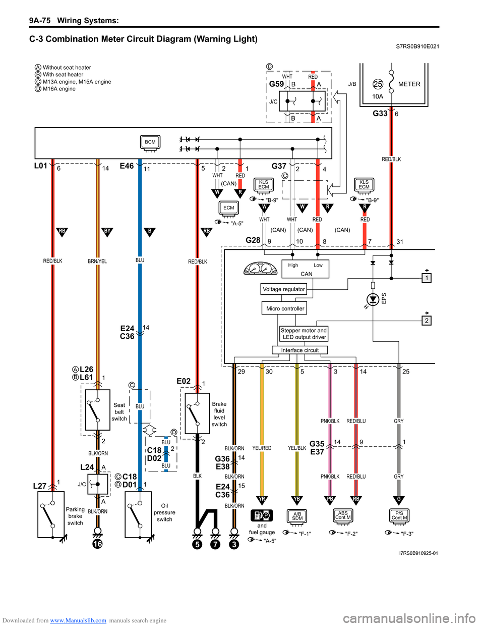
C-3 Combination Meter Circuit Diagram (Warning Light)S7RS0B910E021
J/BMETER
10A25
G2831
3
E24
C3615
G36 E3814
Stepper motor and
LED output driver
Voltage regulator
Interface circuit
Micro controllerEPS
G336
RED/BLK
145293025
PNK/BLKGRY
GRY
RED/BLU
PNK/BLK
BLK/ORN
BLK/ORN
BLK/ORN
RED/BLU
P/S
Cont M
"F-3"
RBPBYBYR
YEL/BLKYEL/RED
A/B
SDM
"F-1""A-5"
ABS
Cont.M
"F-2"
G
CAN
High Low
WHTWHTRED
WHTRED
RED
RW
109 8
6L0114
RED/BLKBRN/YEL
L271
Parking
brake
switch
1
2
A
A
16
BLK/ORN
BLK/ORN
J/C
L24
Seat belt
switch
Oil
pressure switch
E24
C3614
BLU
BLU
1C18
D01
RED/BLK
E021
Brake
fluid
level
switch
and
fuel gauge
2
53
BLK
11 5E46G372
4
RW
W
21WHTRED
"A-5"
1
2
RBBBYRB
7
BCM
ECM"B-9"
KLS
ECM
7
R"B-9"
KLS
ECM
Without seat heater
AWith seat heater
BM13A engine, M15A engine
CM16A engine
D
C
C
C
D
(CAN)
(CAN) (CAN)
(CAN)
L26
L61AB
B
BA
A
J/C
G59
BLU
BLU
D
C18
D022G35 E371419
D
I7RS0B910925-01
Page 1256 of 1496

Downloaded from www.Manualslib.com manuals search engine 9A-85 Wiring Systems:
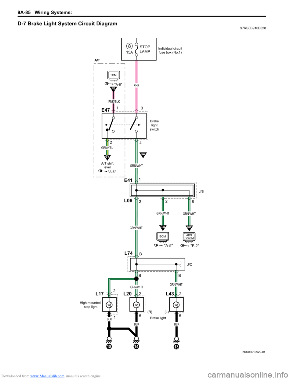
D-7 Brake Light System Circuit DiagramS7RS0B910E028
Brakelight
switch
(R)
Brake light
PNK
BLK
(L)
15A
8STOP
LAMP
E47
L43
GRN/WHT
GRN/WHT
GRN/WHT
5
4
1
L0628
E411
J/B
"F-2"
ABS
Cont.M
GRN/WHT
2
"A-5"
ECM
13
GW
GWGW
TCM
PB
PNK/BLK
"A-6"
GRN/YEL
A/T shift
lever
GY
"A-6"
2 3
A/T
18
Individual circuit
fuse box (No.1)
B
BL74
J/C
L202
5L172
1
High mounted stop light
14
BLK
BLK
2
B
GRN/WHTGRN/WHT
I7RS0B910929-01
Page 1266 of 1496

Downloaded from www.Manualslib.com manuals search engine 9A-95 Wiring Systems:
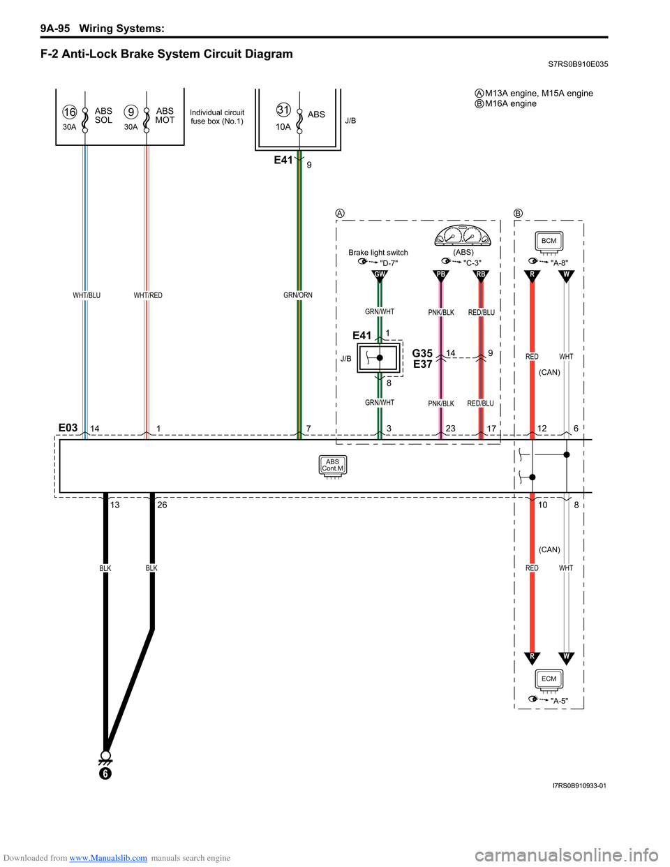
F-2 Anti-Lock Brake System Circuit DiagramS7RS0B910E035
1326
14
1 3
23
17
E03
ABS
Cont.M
BCM
BLK
30A
ABS
SOL16
30A
ABS
MOT9
WHT/REDWHT/BLU
GRN/WHT
6
BLKREDWHT
PNK/BLK
PB
PNK/BLK
RB
RED/BLU
RED/BLU
149G35 E37
"C-3""A-8"
ECM
"A-5"
J/B10A ABS
31
E419
GRN/ORN
7
GW"D-7"Brake light switch
(CAN)
(CAN)
(ABS)
GRN/WHT
J/B
E411
8
Individual circuit fuse box (No.1)
108
12
RED
R
6
WHT
W
RW
M13A engine, M15A engine
M16A engineA
AB
B
I7RS0B910933-01