2004 SUBARU IMPREZA WRX steering
[x] Cancel search: steeringPage 95 of 491
1-68
Seat, seatbelt and SRS airbags
C) After deployment, SRS side airbag starts to deflate im-
mediately.
The SRS side airbag can function only when the igni-
tion switch is in the “ON” position.
The driver’s and front passenger’s SRS side airbags
deploy independently of each other since each has its
own impact sensor. Also, the SRS side airbag deploys
independently of the frontal airbags in the steering
wheel and instrument panel.
An impact sensor is incorporated into each of the ve-
hicle’s center pillars. If either sensor detects a certain
predetermined amount of force during a side impact
collision, the control module sends a signal to the side
airbag module on the impacted side of the vehicle, in-
structing it to inflate the SRS side airbag. Then the
side airbag module produces gas, which instantly in-
flates the SRS side airbag. After the deployment, the
SRS side airbag immediately starts to deflate. The
time required from detecting impact to the deflation of
the SRS side airbag after deployment is shorter than
the blink of an eye.
The SRS side airbag deploys even when no one occu-
pies the seat on the side on which an impact is ap-
plied. When the SRS side airbag deploys, a sudden, fairly
loud inflation noise will be heard and some smoke will
be released. These occurrences are normal result of
the deployment. This smoke does not indicate a fire in
the vehicle.
Do not touch the SRS side airbag system com-
ponents around the front seatback with bare
hands right after deployment. Doing so can
cause burns because the components can be
very hot as a result of deployment.
The SRS side airbag is designed to deploy in the event
of an accident involving a moderate to severe side im-
pact collision. It is basically not designed to deploy in
lesser side impact. Also, it is basically not designed to
deploy in frontal or rear impacts because SRS side air-
bag deployment would not help the occupant in those
situations.
Each SRS side airbag is designed to function on a one-time-only basis.
SRS side airbag deployment depends on the level of
force experienced in the passenger compartment dur-
ing a side impact collision. That level differs from one
Page 101 of 491
1-74
Seat, seatbelt and SRS airbags
"
Under the center console
" Inside each front fender
" Steering wheel and column and nearby areas
" Top of the dashboard on front passenger’s
side and nearby areas " Each front seat and nearby area (only for ve-
hicles with SRS side airbags)
" Inside each center pillar
In the event that the SRS airbag is deployed, re-
placement of the system should be performed
only by an authorized SUBARU dealer. When the
components of the SRS airbag system are re-
placed, use only genuine SUBARU parts.
To ensure their long-term reliability, the SRS airbags
must be inspected by a SUBARU dealer ten years af-
ter the date of manufacture, which is shown on the cer-
tification plate attached to the driver’s door jamb.
NOTE
In the following cases, contact your SUBARU deal-
er as soon as possible. " The front part of the vehicle was involved in an
accident in which the SRS frontal airbags did not
deploy. " The pad section of the steering wheel or front passenger’s frontal airbag cover is scratched,
cracked, or otherwise damaged.
In addition, if your vehicle is equipped with SRS
side airbags, contact your SUBARU dealer as
soon as possible in the following cases. "
Either center pillar or a nearby area of the vehi-
cle was involved in an accident in which the SRS
side airbag did not deploy. " The fabric or leather of either front seatback is
cut, frayed, or otherwise damaged. ! Precautions against vehicle modifica- tion
"To avoid accidental activation of the system
or rendering the system inoperative, which may
result in serious injury, no modifications
should be made to any components or wiring of
the SRS airbag system.
This includes following modifications: "Installation of custom steering wheels
" Attachment of additional trim materials to
the dashboard " Installation of custom seats (for vehicles
Page 139 of 491

3-2
Instruments and controls
Daytime running light system (except U.S. spec. WRX-STi) .............................................. 3-31
Turn signal lever ........................................... 3-31
Illumination brightness control ................... 3-32
Illumination brightness control (WRX-STi) 3-33
Headlight beam leveler (U.S. spec. WRX-STi) ................................ 3-33
Parking light switch ..................................... 3-34
Fog light switch (if equipped) ..................... 3-35
Wiper and washer ......................................... 3-35 Windshield wiper and washer switches ......... 3-37
Rear window wiper and washer switch – Wagon .......................................................... 3-39
Rear window defogger switch ..................... 3-40
Windshield wiper deicer (if equipped) ....... 3-42
Intercooler water spray switch (WRX-STi) . 3-43
Mirrors ........................................................... 3-44 Inside mirror ...................................................... 3-44
Outside mirrors ................................................. 3-47
Tilt steering wheel ........................................ 3-49
Horn ............................................................... 3-50
Page 140 of 491
3-3
Instruments and controls
– CONTINUED –
Instruments and controlsIgnition switch
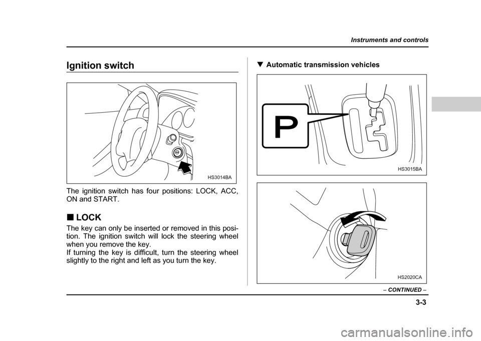
The ignition switch has four positions: LOCK, ACC,
ON and START. !LOCK
The key can only be inserted or removed in this posi-
tion. The ignition switch will lock the steering wheel
when you remove the key.
If turning the key is difficult, turn the steering wheel
slightly to the right and left as you turn the key. !
Automatic transmission vehicles
HS3014BA
HS3015BA
HS2020CA
Page 141 of 491
3-4
Instruments and controls
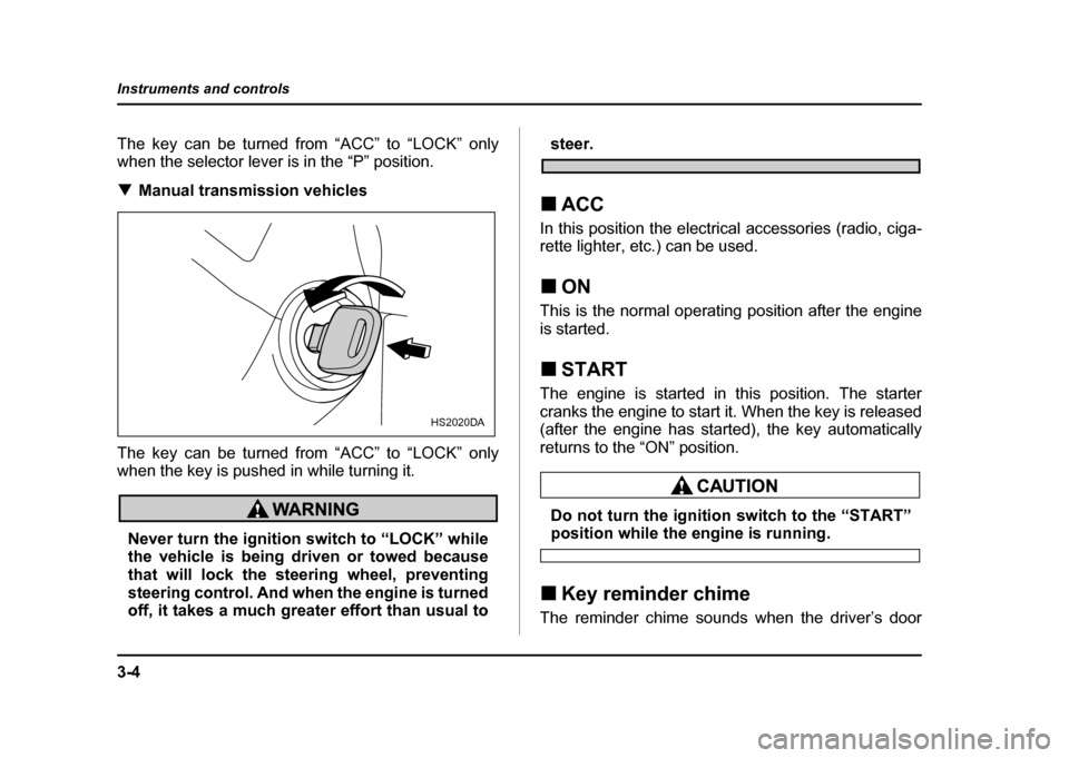
The key can be turned from “ACC” to “LOCK” only
when the selector lever is in the “P” position. !
Manual transmission vehicles
The key can be turned from “ACC” to “LOCK” only
when the key is pushed in while turning it.
Never turn the ignition switch to “LOCK” while
the vehicle is being driven or towed because
that will lock the steering wheel, preventing
steering control. And when the engine is turned
off, it takes a much greater effort than usual to
steer.
! ACC
In this position the electrical accessories (radio, ciga-
rette lighter, etc.) can be used. ! ON
This is the normal operating position after the engine
is started. ! START
The engine is started in this position. The starter
cranks the engine to start it. When the key is released
(after the engine has started), the key automatically
returns to the “ON” position.
Do not turn the ignition switch to the “START”position while the engine is running.
! Key reminder chime
The reminder chime sounds when the driver’s door
HS2020DA
Page 142 of 491
3-5
Instruments and controls
– CONTINUED –
opens and the key is in the “LOCK” or “ACC” positions.
The chime stops when the key is removed from the ig- nition switch. !Ignition switch light (if equipped)
For easy access to the ignition switch in the dark, the
ignition switch light comes on when driver’s door is
opened. The light remains on for 10 seconds and goes
out after driver’s door is closed or if the key is turned
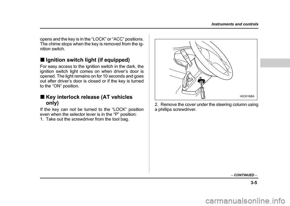
to the “ON” position. ! Key interlock release (AT vehicles only)
If the key can not be turned to the “LOCK” position
even when the selector lever is in the “P” position:
1. Take out the screwdriver from the tool bag. 2. Remove the cover under the steering column using
a phillips screwdriver.
HS3016BA
Page 186 of 491
3-49
Instruments and controls
– CONTINUED –
frosting or defogging is desired when you restart your
vehicle, you have to push the switch to turn it on again.
NOTE
While the outside mirror defogger is operating, the
rear window defogger also operates.
To prevent the battery from being discharged,
do not operate the defogger continuously for
any longer than necessary.
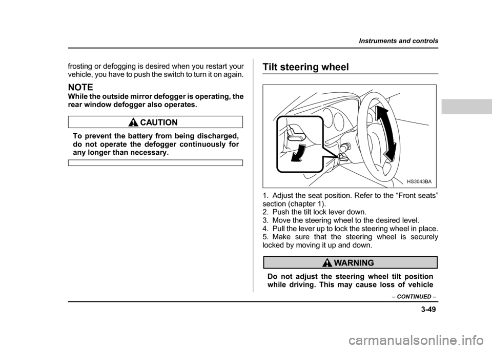
Tilt steering wheel
1. Adjust the seat position. Refer to the “Front seats”
section (chapter 1).
2. Push the tilt lock lever down.
3. Move the steering wheel to the desired level.
4. Pull the lever up to lock the steering wheel in place.
5. Make sure that the steering wheel is securely
locked by moving it up and down.
Do not adjust the steering wheel tilt position
while driving. This may cause loss of vehicle
HS3043BA
Page 270 of 491

7-1
7
Starting and operating
F uel .. ... ... ... .. ... ... ... ... .. ... ... ... ... ... .. ... ... ... ... .. ... ... 7-2
F uel re quire ments ..................... ..................... ... 7-2
Fuel filler lid and cap ........................................ 7-4
State emission testing (U.S. only) ............... 7-7
Preparing to drive ......................................... 7-9
Starting the engine ....................................... 7-9 Manual transmission vehicle ........................... 7-9
Automatic transmission vehicle ...................... 7-10
Starting the engine during cold weather below −4 °F ( −20 °C) ......................................... 7-10
Starting a flooded engine ................................. 7-11
Stopping the engine ..................................... 7-11
Manual transmission – 6 speed (WRX-STi) 7-12 Selecting reverse gear ...................................... 7-12
Shifting speeds ................................................. 7-13
Driving tips ........................................................ 7-14
Manual transmission – 5 speed (except WRX-STi) ...................................... 7-15Shifting speeds ................................................. 7-15
Driving tips ........................................................ 7-17
Driver’s Control Center Differential (DCCD) (WRX-STi) ..................................... 7-18Auto mode ......................................................... 7-18
Manual mode ..................................................... 7-19
Temporary release ............................................ 7-21
Automatic transmission ............................... 7-21 Selector lever for automatic transmission ..... 7-22
Shift lock release .............................................. 7-26
Limited slip differential (LSD) (if equipped) 7-27 Power steering .............................................. 7-28
Braking ........................................................... 7-28
Braking tips ....................................................... 7-28
Brake system .................................................... 7-29
Disc brake pad wear warning indicators ........ 7-29
ABS (Anti-lock Brake System) ..................... 7-30 ABS system self-check .................................... 7-30
ABS warning light ............................................. 7-31
Electronic Brake Force Distribution (EBD) system ........................................................ 7-32Steps to take if EBD system fails .................... 7-33
Parking your vehicle ..................................... 7-34 Parking brake .................................................... 7-34
Parking tips ....................................................... 7-35
Cruise control ................................................ 7-37 To set cruise control ........................................ 7-37
To temporarily cancel the cruise control ....... 7-39
To turn off the cruise control ........................... 7-40
To change the cruising speed ......................... 7-40