2004 SUBARU FORESTER check engine light
[x] Cancel search: check engine lightPage 1489 of 2870

ME(H4DOTC)-33
MECHANICAL
Ignition Timing
4. Ignition Timing
A: INSPECTION
1. USING SUBARU SELECT MONITOR
1) Before checking the ignition timing speed, check
the following:
(1) Ensure the air cleaner element is free from
clogging, spark plugs are in good condition, and
that hoses are connected properly.
(2) Ensure the malfunction indicator light does
not illuminate.
2) Warm-up the engine.
3) Stop the engine, and then turn the ignition switch
to OFF.
4) Insert the cartridge to Subaru Select Monitor.
5) Connect the Subaru Select Monitor to data link
connector.
6) Turn the ignition switch to ON, and Subaru Se-
lect Monitor switch to ON.
7) Select the {2. Each System Check} in Main
Menu.
8) Select the {Engine Control System} in Selection
Menu.
9) Select the {1. Current Data Display & Save} in
Engine Control System Diagnosis.
10) Select the {1.12 Data Display} in Data Display
Menu.
11) Start the engine and check the ignition timing at
idle speed.
Ignition timing [BTDC/rpm]:
2.0 L model
12
°±10°/700
2.5 L model
17
°±10°/700
If the timing is not correct, check the ignition control
system. Refer to Engine Control System.
Page 1491 of 2870

ME(H4DOTC)-35
MECHANICAL
Engine Oil Pressure
6. Engine Oil Pressure
A: INSPECTION
1) Remove the oil pressure switch from engine cyl-
inder block.
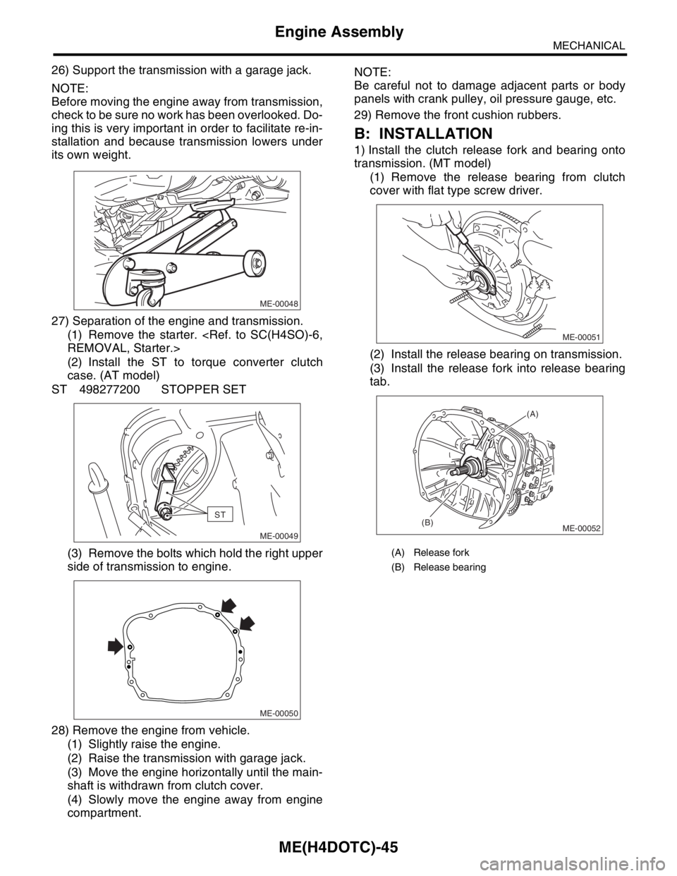
2) Connect the oil pressure gauge hose to cylinder
block.
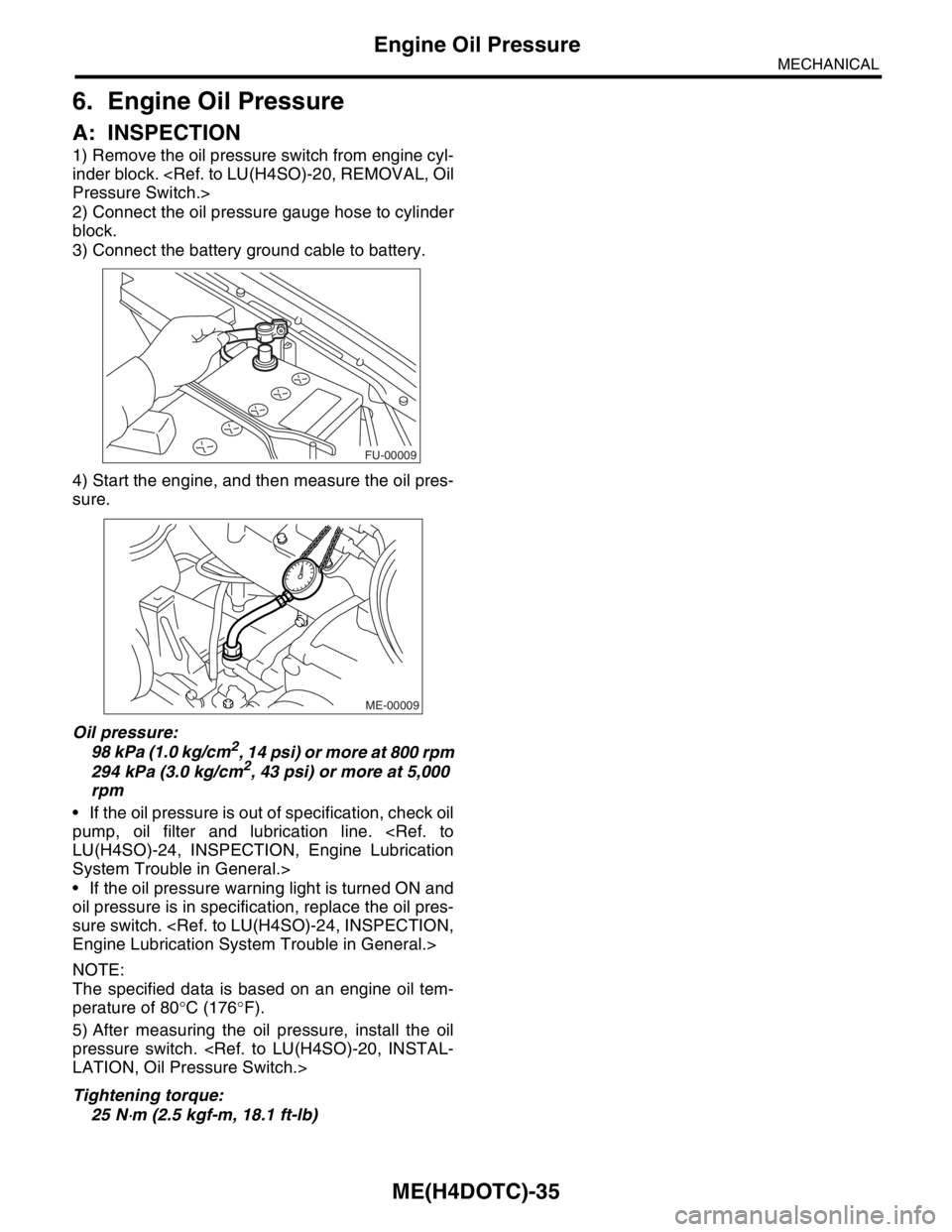
3) Connect the battery ground cable to battery.
4) Start the engine, and then measure the oil pres-
sure.
Oil pressure:
98 kPa (1.0 kg/cm
2, 14 psi) or more at 800 rpm
294 kPa (3.0 kg/cm2, 43 psi) or more at 5,000
rpm
If the oil pressure is out of specification, check oil
pump, oil filter and lubrication line.
System Trouble in General.>
If the oil pressure warning light is turned ON and
oil pressure is in specification, replace the oil pres-
sure switch.
NOTE:
The specified data is based on an engine oil tem-
perature of 80°C (176°F).
5) After measuring the oil pressure, install the oil
pressure switch.
Tightening torque:
25 N
⋅m (2.5 kgf-m, 18.1 ft-lb)
FU-00009
ME-00009
Page 1503 of 2870

ME(H4DOTC)-45
MECHANICAL
Engine Assembly
26) Support the transmission with a garage jack.
NOTE:
Before moving the engine away from transmission,
check to be sure no work has been overlooked. Do-
ing this is very important in order to facilitate re-in-
stallation and because transmission lowers under
its own weight.
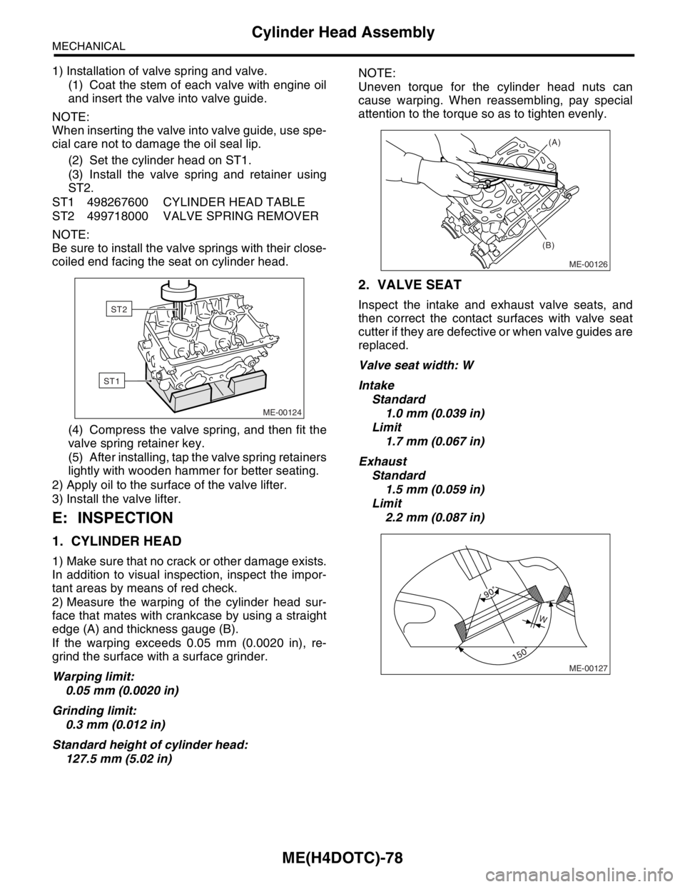
27) Separation of the engine and transmission.
(1) Remove the starter.
(2) Install the ST to torque converter clutch
case. (AT model)
ST 498277200 STOPPER SET
(3) Remove the bolts which hold the right upper
side of transmission to engine.
28) Remove the engine from vehicle.
(1) Slightly raise the engine.
(2) Raise the transmission with garage jack.
(3) Move the engine horizontally until the main-
shaft is withdrawn from clutch cover.
(4) Slowly move the engine away from engine
compartment.NOTE:
Be careful not to damage adjacent parts or body
panels with crank pulley, oil pressure gauge, etc.
29) Remove the front cushion rubbers.
B: INSTALLATION
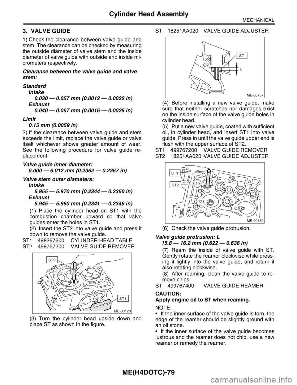
1) Install the clutch release fork and bearing onto
transmission. (MT model)
(1) Remove the release bearing from clutch
cover with flat type screw driver.
(2) Install the release bearing on transmission.
(3) Install the release fork into release bearing
tab.
ME-00048
ST
ME-00049
ME-00050
(A) Release fork
(B) Release bearing
ME-00051
ME-00052
(A)
(B)
Page 1536 of 2870

ME(H4DOTC)-78
MECHANICAL
Cylinder Head Assembly
1) Installation of valve spring and valve.
(1) Coat the stem of each valve with engine oil
and insert the valve into valve guide.
NOTE:
When inserting the valve into valve guide, use spe-
cial care not to damage the oil seal lip.
(2) Set the cylinder head on ST1.
(3) Install the valve spring and retainer using
ST2.
ST1 498267600 CYLINDER HEAD TABLE
ST2 499718000 VALVE SPRING REMOVER
NOTE:
Be sure to install the valve springs with their close-
coiled end facing the seat on cylinder head.
(4) Compress the valve spring, and then fit the
valve spring retainer key.
(5) After installing, tap the valve spring retainers
lightly with wooden hammer for better seating.
2) Apply oil to the surface of the valve lifter.
3) Install the valve lifter.
E: INSPECTION
1. CYLINDER HEAD
1) Make sure that no crack or other damage exists.
In addition to visual inspection, inspect the impor-
tant areas by means of red check.
2) Measure the warping of the cylinder head sur-
face that mates with crankcase by using a straight
edge (A) and thickness gauge (B).
If the warping exceeds 0.05 mm (0.0020 in), re-
grind the surface with a surface grinder.
Warping limit:
0.05 mm (0.0020 in)
Grinding limit:
0.3 mm (0.012 in)
Standard height of cylinder head:
127.5 mm (5.02 in)NOTE:
Uneven torque for the cylinder head nuts can
cause warping. When reassembling, pay special
attention to the torque so as to tighten evenly.
2. VALVE SEAT
Inspect the intake and exhaust valve seats, and
then correct the contact surfaces with valve seat
cutter if they are defective or when valve guides are
replaced.
Valve seat width: W
Intake
Standard
1.0 mm (0.039 in)
Limit
1.7 mm (0.067 in)
Exhaust
Standard
1.5 mm (0.059 in)
Limit
2.2 mm (0.087 in)
ME-00124
ST1
ST2
ME-00126
(A)
(B)
ME-00127
W
Page 1537 of 2870

ME(H4DOTC)-79
MECHANICAL
Cylinder Head Assembly
3. VALVE GUIDE
1) Check the clearance between valve guide and
stem. The clearance can be checked by measuring
the outside diameter of valve stem and the inside
diameter of valve guide with outside and inside mi-
crometers respectively.
Clearance between the valve guide and valve
stem:
Standard
Intake
0.030 — 0.057 mm (0.0012 — 0.0022 in)
Exhaust
0.040 — 0.067 mm (0.0016 — 0.0026 in)
Limit
0.15 mm (0.0059 in)
2) If the clearance between valve guide and stem
exceeds the limit, replace the valve guide or valve
itself whichever shows greater amount of wear.
See the following procedure for valve guide re-
placement.
Valve guide inner diameter:
6.000 — 6.012 mm (0.2362 — 0.2367 in)
Valve stem outer diameters:
Intake
5.955 — 5.970 mm (0.2344 — 0.2350 in)
Exhaust
5.945 — 5.960 mm (0.2341 — 0.2346 in)
(1) Place the cylinder head on ST1 with the
combustion chamber upward so that valve
guides enter the holes in ST1.
(2) Insert the ST2 into valve guide and press it
down to remove the valve guide.
ST1 498267600 CYLINDER HEAD TABLE
ST2 499767200 VALVE GUIDE REMOVER
(3) Turn the cylinder head upside down and
place ST as shown in the figure.ST 18251AA020 VALVE GUIDE ADJUSTER
(4) Before installing a new valve guide, make
sure that neither scratches nor damages exist
on the inside surface of the valve guide holes in
cylinder head.
(5) Put a new valve guide, coated with sufficient
oil, in cylinder head, and insert ST1 into valve
guide. Press in until the valve guide upper end is
flush with the upper surface of ST2.
ST1 499767200 VALVE GUIDE REMOVER
ST2 18251AA020 VALVE GUIDE ADJUSTER
(6) Check the valve guide protrusion.
Valve guide protrusion: L
15.8 — 16.2 mm (0.622 — 0.638 in)
(7) Ream the inside of valve guide with ST.
Gently rotate the reamer clockwise while press-
ing it lightly into the valve guide, and return it
also rotating clockwise.
(8) After reaming, clean the valve guide to re-
move chips.
ST 499767400 VALVE GUIDE REAMER
CAUTION:
Apply engine oil to ST when reaming.
NOTE:
If the inner surface of the valve guide is torn, the
edge of the reamer should be slightly ground with
an oil stone.
If the inner surface of the valve guide becomes
lustrous and the reamer does not chip, use a new
reamer or remedy the reamer.
ME-00128
ST1
ST2ME-00757
ST
L
ME-00130
ST1
ST2
Page 1631 of 2870

ENGINE (DIAGNOSTIC)
EN(H4DOTC)
Page
1. Basic Diagnostics Procedure ......................................................................2
2. Check List for Interview ...............................................................................4
3. General Description ....................................................................................6
4. Electrical Component Location ...................................................................9
5. Engine Control Module (ECM) I/O Signal .................................................23
6. Engine Condition Data ..............................................................................27
7. Transmission Control Module (TCM) I/O Signal .......................................28
8. Data Link Connector .................................................................................29
9. OBD-II General Scan Tool ........................................................................30
10. Subaru Select Monitor...............................................................................33
11. Read Diagnostic Trouble Code (DTC) ......................................................39
12. Inspection Mode ........................................................................................40
13. Drive Cycle ................................................................................................45
14. Clear Memory Mode..................................................................................47
15. Compulsory Valve Operation Check Mode ...............................................48
16. Malfunction Indicator Light ........................................................................50
17. Diagnostics for Engine Starting Failure .....................................................59
18. List of Diagnostic Trouble Code (DTC) .....................................................74
19. Diagnostic Procedure with Diagnostic Trouble Code (DTC) .....................80
20. General Diagnostic Table........................................................................295
Page 1632 of 2870

EN(H4DOTC)-2
ENGINE (DIAGNOSTIC)
Basic Diagnostics Procedure
1. Basic Diagnostics Procedure
A: PROCEDURE
1. ENGINE
Step Check Yes No
1 CHECK ENGINE START FAILURE.
1) Ask the customer when and how the trou-
ble occurred using the interview check list.
2) Start the engine.Does the engine start? Go to step 2.Inspection using
“Diagnostics for
Engine Start Fail-
ure”.
Diagnostics for
Engine Starting
Fai lu r e.>
2 CHECK ILLUMINATION OF MALFUNCTION
INDICATOR LIGHT.Does malfunction indicator
light illuminate?Go to step 3.Inspection using
“General Diagnos-
tic Table”.
295, General Diag-
nostic Table.>
3 CHECK INDICATION OF DTC ON DISPLAY.
1) Turn the ignition switch to OFF.
2) Connect the Subaru Select Monitor or the
OBD-II general scan tool to data link connec-
tor.
3) Turn the ignition switch to ON and the Sub-
aru Select Monitor or OBD-II general scan tool
switch to ON.
4) Read the DTC on the Subaru Select Moni-
tor or OBD-II general scan tool.Does the Subaru Select Moni-
tor or OBD-II general scan tool
indicate DTC?Record the
DTC.Repair the
trouble cause.
List of Diagnostic
Trouble Code
(DTC).> Go to
step 4.Repair the related
parts.
N
OTE:
If DTC is not shown
on display although
the malfunction in-
dicator light illumi-
nates, perform the
diagnostics for mal-
function indicator
light circuit or com-
bination meter.
Malfunction Indica-
tor Light.>
4 PERFORM THE DIAGNOSIS.
1) Perform clear memory mode.
2) Perform the “INSPECTION MODE”.
tor or OBD-II general scan tool
indicate DTC?Check on “Diag-
nostic Chart with
Diagnostic Trou-
ble Code (DTC)”
Diagnostic Proce-
dure with Diagnos-
tic Trouble Code
(DTC).>Finish the diagno-
sis.
Page 1634 of 2870

EN(H4DOTC)-4
ENGINE (DIAGNOSTIC)
Check List for Interview
2. Check List for Interview
A: INSPECTION
1. CHECK LIST NO. 1
Check the following items when problem has occurred.
NOTE:
Use copies of this page for interviewing customers.
Customer’s name Engine No.
Date of sale Fuel brand
Date of repair
Odometer readingkm
V.I.N.miles
Weather❏ Fine
❏ Cloudy
❏ Rainy
❏ Snowy
❏ Va r i o u s / O t h e r s :
Ambient air temperature°C (°F)
❏ Hot
❏ War m
❏ Cool
❏ Cold
Place❏ Highway
❏ Suburbs
❏ Inner city
❏ Uphill
❏ Downhill
❏ Rough road
❏ Others:
Engine temperature❏ Cold
❏ War ming-up
❏ After warming-up
❏ Any temperature
❏ Others:
Engine speed rpm
Vehicle speed km/h (MPH)
Driving conditions❏ Not affected
❏ At starting
❏ While idling
❏ At racing
❏ While accelerating
❏ While cruising
❏ While decelerating
❏ While turning (RH/LH)
Headlight❏ ON / ❏ OFF Rear defogger❏ ON / ❏ OFF
Blower❏ ON / ❏ OFF Radio❏ ON / ❏ OFF
A/C compressor❏ ON / ❏ OFF CD/Cassette❏ ON / ❏ OFF
Radiator fan❏ ON / ❏ OFF Car phone❏ ON / ❏ OFF
Fr o nt wi pe r❏ ON / ❏ OFF CB❏ ON / ❏ OFF
Rear Wiper❏ ON / ❏ OFF