2004 NISSAN XTERRA spare tire
[x] Cancel search: spare tirePage 245 of 296

Tire and loading information label (for
US)
s1Seating capacity: The maximum number of
occupants that should be seated in the ve-
hicle.
s2Vehicle load limit: See loading information in
the Technical and consumer information
section.
s3Original tire size: The size of the tires origi-
nally installed on the vehicle at the factory.
s4Recommended cold tire inflation pressure:
Inflate the tires to this pressure when the
tires are cold. Tires are considered COLD
after the vehicle has been parked for 3 or
more hours, or driven less than 1 mile (1.6
km) at moderate speeds. The recommended
cold tire inflation is set by the manufacturer
to provide the best tire wear and vehicle
handling characteristics based on the ve-
hicles GVWR.
s5Tire size – refer to “Tire labeling” later in this
section.
s6ands7Spare tire size or compact spare tire
size (if so equipped) .
type a
LDI0392
Maintenance and do-it-yourself8-41
ZREVIEW COPY:Ð2004 Xterra(xtr)
Owners Manual(owners)ÐUSA English(nna)
11/06/03Ðcathy
X
Page 246 of 296

Tire and loading information label (for
US)
s1Original tire size: The size of the tires origi-
nally installed on the vehicle at the factory.
s2Recommended cold tire inflation pressure:
Inflate the tires to this pressure when the
tires are cold. Tires are considered COLD
after the vehicle has been parked for 3 or
more hours, or driven less than 1 mile (1.6
km) at moderate speeds. The recommended
cold tire inflation is set by the manufacturer
to provide the best tire wear and vehicle
handling characteristics based on the ve-
hicles GVWR.
s3Spare tire size or compact spare tire size (if
so equipped) .
Checking tire pressure
1. Remove the valve stem cap from the tire.
2. Press the pressure gauge squarely onto the
valve stem. Do not press too hard or force
the valve stem sideways, or air will escape. If
the hissing of air escaping from the tire is
heard while checking the pressure, reposi-
tion the gauge to eliminate this leakage.
3. Remove the gauge.
4. Read the tire pressure on the gauge stem
and compare to the specification shown on
the Tire and Loading Information label.
type b
LDI0421LDI0393
8-42Maintenance and do-it-yourself
ZREVIEW COPY:Ð2004 Xterra(xtr)
Owners Manual(owners)ÐUSA English(nna)
11/06/03Ðcathy
X
Page 247 of 296

5. Add air to the tire as needed. If too much air
is added, press the core of the valve stem
briefly with the tip of the gauge stem to
release pressure. Recheck the pressure and
add or release air as needed.
6. Install the valve stem cap.
7. Check the pressure of all other tires, includ-
ing the spare.
Size Cold Tire Infla-
tion Pressure
Front
Original TireP265/70R15
P265/70R16
P265/65R17210 kPa, 30 PSI
Rear
Original TireP265/70R15
P265/70R16
P265/65R17210 kPa, 30 PSI
Spare Tire P265/70R15
P265/70R16
P265/65R17210 kPa, 30 PSI
TIRE LABELING
Federal law requires tire manufacturers to place
standardized information on the sidewall of all
tires. This information identifies and describes
the fundamental characteristics of the tire and
also provides the tire identification number (TIN)
for safety standard certification. The TIN can be
used to identify the tire in case of a recall.
WDI0394
Maintenance and do-it-yourself8-43
ZREVIEW COPY:Ð2004 Xterra(xtr)
Owners Manual(owners)ÐUSA English(nna)
10/23/03Ðdebbie
X
Page 251 of 296

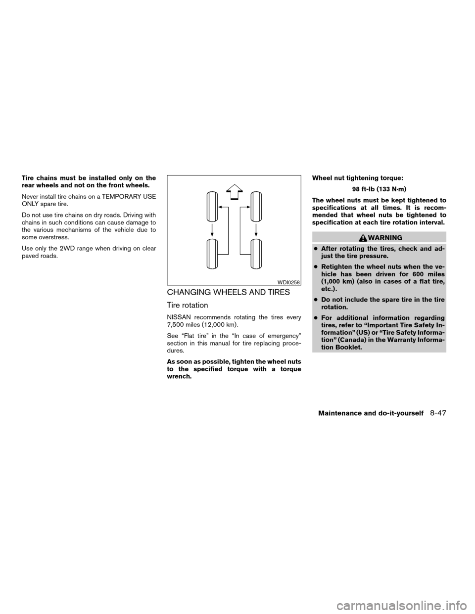
Tire chains must be installed only on the
rear wheels and not on the front wheels.
Never install tire chains on a TEMPORARY USE
ONLY spare tire.
Do not use tire chains on dry roads. Driving with
chains in such conditions can cause damage to
the various mechanisms of the vehicle due to
some overstress.
Use only the 2WD range when driving on clear
paved roads.
CHANGING WHEELS AND TIRES
Tire rotation
NISSAN recommends rotating the tires every
7,500 miles (12,000 km) .
See “Flat tire” in the “In case of emergency”
section in this manual for tire replacing proce-
dures.
As soon as possible, tighten the wheel nuts
to the specified torque with a torque
wrench.Wheel nut tightening torque:
98 ft-lb (133 N·m)
The wheel nuts must be kept tightened to
specifications at all times. It is recom-
mended that wheel nuts be tightened to
specification at each tire rotation interval.
WARNING
cAfter rotating the tires, check and ad-
just the tire pressure.
cRetighten the wheel nuts when the ve-
hicle has been driven for 600 miles
(1,000 km) (also in cases of a flat tire,
etc.) .
cDo not include the spare tire in the tire
rotation.
cFor additional information regarding
tires, refer to “Important Tire Safety In-
formation” (US) or “Tire Safety Informa-
tion” (Canada) in the Warranty Informa-
tion Booklet.
WDI0258
Maintenance and do-it-yourself8-47
ZREVIEW COPY:Ð2004 Xterra(xtr)
Owners Manual(owners)ÐUSA English(nna)
10/23/03Ðdebbie
X
Page 252 of 296

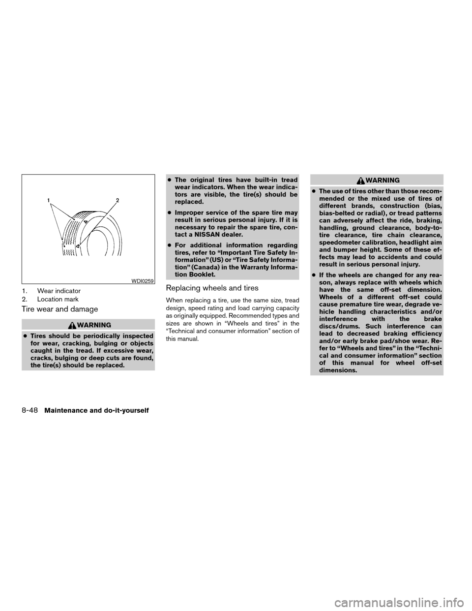
1. Wear indicator
2. Location mark
Tire wear and damage
WARNING
cTires should be periodically inspected
for wear, cracking, bulging or objects
caught in the tread. If excessive wear,
cracks, bulging or deep cuts are found,
the tire(s) should be replaced.cThe original tires have built-in tread
wear indicators. When the wear indica-
tors are visible, the tire(s) should be
replaced.
cImproper service of the spare tire may
result in serious personal injury. If it is
necessary to repair the spare tire, con-
tact a NISSAN dealer.
cFor additional information regarding
tires, refer to “Important Tire Safety In-
formation” (US) or “Tire Safety Informa-
tion” (Canada) in the Warranty Informa-
tion Booklet.
Replacing wheels and tires
When replacing a tire, use the same size, tread
design, speed rating and load carrying capacity
as originally equipped. Recommended types and
sizes are shown in “Wheels and tires” in the
“Technical and consumer information” section of
this manual.
WARNING
cThe use of tires other than those recom-
mended or the mixed use of tires of
different brands, construction (bias,
bias-belted or radial) , or tread patterns
can adversely affect the ride, braking,
handling, ground clearance, body-to-
tire clearance, tire chain clearance,
speedometer calibration, headlight aim
and bumper height. Some of these ef-
fects may lead to accidents and could
result in serious personal injury.
cIf the wheels are changed for any rea-
son, always replace with wheels which
have the same off-set dimension.
Wheels of a different off-set could
cause premature tire wear, degrade ve-
hicle handling characteristics and/or
interference with the brake
discs/drums. Such interference can
lead to decreased braking efficiency
and/or early brake pad/shoe wear. Re-
fer to “Wheels and tires” in the “Techni-
cal and consumer information” section
of this manual for wheel off-set
dimensions.
WDI0259
8-48Maintenance and do-it-yourself
ZREVIEW COPY:Ð2004 Xterra(xtr)
Owners Manual(owners)ÐUSA English(nna)
10/23/03Ðdebbie
X
Page 253 of 296

cWhen a spare tire is mounted or a wheel
is replaced, the low tire pressure warn-
ing system will not function. Contact
your NISSAN dealer as soon as pos-
sible for tire replacement and/or sys-
tem resetting (for models with the low
tire pressure warning system) .
cDo not install a deformed wheel or tire
even if it has been repaired. Such
wheels or tires could have structural
damage and could fail without warning.
cThe use of retread tires is not
recommended.
cFor additional information regarding
tires, refer to “Important Tire Safety In-
formation” (US) or “Tire Safety Informa-
tion” (Canada) in the Warranty Informa-
tion Booklet.Four-wheel drive models
CAUTION
Always use tires of the same type, size,
brand, construction (bias, bias-belted or
radial) , and tread pattern on all four
wheels. Failure to do so may result in a
circumference difference between tires
on the front and rear axles which will
cause excessive tire wear and may dam-
age the transmission, transfer case and
differential gears.
If excessive tire wear is found, it is recommended
that all four tires be replaced with tires of the
same size, brand, construction and tread pattern.
The tire pressure and wheel alignment should
also be checked and corrected as necessary.
Contact a NISSAN dealer.
Wheel balance
Unbalanced wheels may affect vehicle handling
and tire life. Even with regular use, wheels can get
out of balance. Therefore, they should be bal-
anced as required.
Wheel balance service should be per-
formed with the wheels off the vehicle.
Spin balancing the wheels on the vehicle
could lead to mechanical damage.cFor additional information regarding
tires, refer to “Important Tire Safety
Information” (US) or “Tire Safety Infor-
mation” (Canada) in the Warranty In-
formation Booklet .
Care of wheels
cWash the wheels when washing the vehicle
to maintain their appearance.
cClean the inner side of the wheels when the
wheel is changed or the underside of the
vehicle is washed.
cDo not use abrasive cleaners when washing
the wheels.
cInspect wheel rims regularly for dents or
corrosion. Such damage may cause loss of
pressure or poor seal at the tire bead.
cNISSAN recommends waxing the road
wheels to protect against road salt in areas
where it is used during winter.
Maintenance and do-it-yourself8-49
ZREVIEW COPY:Ð2004 Xterra(xtr)
Owners Manual(owners)ÐUSA English(nna)
10/23/03Ðdebbie
X
Page 262 of 296

WHEELS AND TIRES
Road wheel/offset in (mm) Tire Spare tire size
4X2 XE 15X7J/1.57 (40) Steel
16X7JJ/1.57 (40) AlloyP265/70R15
P265/70R16P265/70R15
P265/70R16
SE 17X8JJ (40) Alloy P265/65R17 P265/65R17
4X4 XE 16X7JJ/1.57 (40) Steel P265/70R16 P265/70R16
SE 17X8JJ (40) Alloy P265/65R17 P265/65R17
DIMENSIONS AND WEIGHTS
Unit: in (mm)
XE XE XE SE SE
4x2 4x2 4x4 4x2 4x4
KA24DE VG33E/VG33ER VG33E/VG33ER VG33E VG33ER VG33E VG33ER
Overall length*1 178 (4,520) 178 (4,520) 178 (4,520) 178 (4,520) 178 (4,520)
Overall width 70.4 (1,788) 70.4 (1,788) 70.4 (1,788) 70.4 (1,788) 70.4 (1,788)
Overall height 73.7 (1,872) 73.7 (1,872) 73.7 (1,872) 74.4 (1,890) 73.9 (1,877) 74.2 (1,885) 73.8 (1,875)
Front tread 60 (1,525) 60 (1,525) 60 (1,525) 60 (1,525) 60 (1,525)
Rear tread 59.3 (1,505) 59.3 (1,505) 59.3 (1,505) 59.3 (1,505) 59.3 (1,505)
Wheelbase 104.3 (2,649) 104.3 (2,649) 104.3 (2,649) 104.3 (2,649) 104.3 (2,649)
Gross vehicle weight rating See the “F.M.V.S.S. certification label” on the driver side door jamb pillar.
lb (kg)
Gross axle weight rating
Front lb (kg)
Rear lb (kg)
9-8Technical and consumer information
ZREVIEW COPY:Ð2004 Xterra(xtr)
Owners Manual(owners)ÐUSA English(nna)
10/23/03Ðdebbie
X
Page 266 of 296

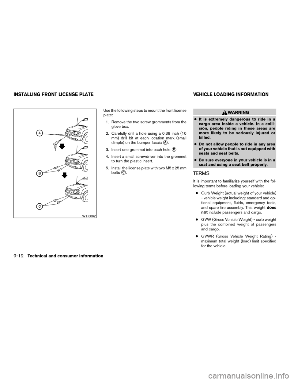
Use the following steps to mount the front license
plate:
1. Remove the two screw gromments from the
glove box.
2. Carefully drill a hole using a 0.39 inch (10
mm) drill bit at each location mark (small
dimple) on the bumper fascia
sA.
3. Insert one grommet into each hole
sB.
4. Insert a small screwdriver into the grommet
to turn the plastic insert.
5. Install the license plate with two M5 x 25 mm
bolts
sC.
WARNING
cIt is extremely dangerous to ride in a
cargo area inside a vehicle. In a colli-
sion, people riding in these areas are
more likely to be seriously injured or
killed.
cDo not allow people to ride in any area
of your vehicle that is not equipped with
seats and seat belts.
cBe sure everyone in your vehicle is in a
seat and using a seat belt properly.
TERMS
It is important to familiarize yourself with the fol-
lowing terms before loading your vehicle:
cCurb Weight (actual weight of your vehicle)
- vehicle weight including: standard and op-
tional equipment, fluids, emergency tools,
and spare tire assembly. This weightdoes
notinclude passengers and cargo.
cGVW (Gross Vehicle Weight) - curb weight
plus the combined weight of passengers
and cargo.
cGVWR (Gross Vehicle Weight Rating) -
maximum total weight (load) limit specified
for the vehicle.
WTI0062
INSTALLING FRONT LICENSE PLATE VEHICLE LOADING INFORMATION
9-12Technical and consumer information
ZREVIEW COPY:Ð2004 Xterra(xtr)
Owners Manual(owners)ÐUSA English(nna)
10/23/03Ðdebbie
X