Page 65 of 328

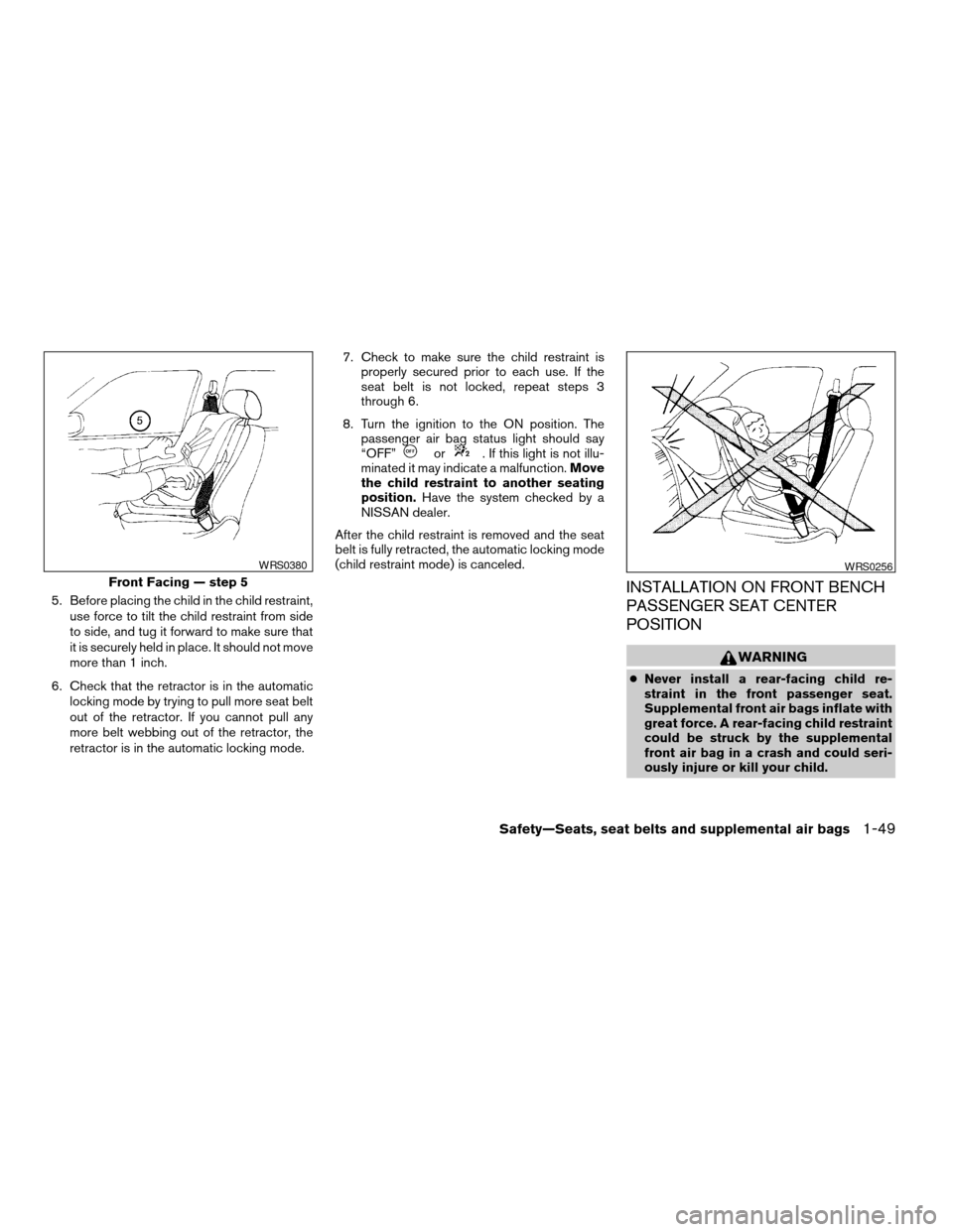
5. Before placing the child in the child restraint,
use force to tilt the child restraint from side
to side, and tug it forward to make sure that
it is securely held in place. It should not move
more than 1 inch.
6. Check that the retractor is in the automatic
locking mode by trying to pull more seat belt
out of the retractor. If you cannot pull any
more belt webbing out of the retractor, the
retractor is in the automatic locking mode.7. Check to make sure the child restraint is
properly secured prior to each use. If the
seat belt is not locked, repeat steps 3
through 6.
8. Turn the ignition to the ON position. The
passenger air bag status light should say
“OFF”
or. If this light is not illu-
minated it may indicate a malfunction.Move
the child restraint to another seating
position.Have the system checked by a
NISSAN dealer.
After the child restraint is removed and the seat
belt is fully retracted, the automatic locking mode
(child restraint mode) is canceled.
INSTALLATION ON FRONT BENCH
PASSENGER SEAT CENTER
POSITION
WARNING
cNever install a rear-facing child re-
straint in the front passenger seat.
Supplemental front air bags inflate with
great force. A rear-facing child restraint
could be struck by the supplemental
front air bag in a crash and could seri-
ously injure or kill your child.
Front Facing — step 5
WRS0380WRS0256
Safety—Seats, seat belts and supplemental air bags1-49
ZREVIEW COPY:Ð2004 Titan(tzw)
Owners Manual(owners)ÐUSA English(nna)
02/20/04Ðtbrooks
X
Page 70 of 328
1. Driver, center and passenger ventila-
tors (P. 4-11)
2. Instrument brightness control (P. 2-26)
3. Headlight and turn signal switch
(P. 2-23)
4. Steering wheel switch for audio control
(if so equipped) (P. 4-36)
5. Driver supplemental air bag/horn
(P. 1-11, P. 2-28)
6. Meters, gauges and warning/indicator
lights (P. 2-3, 2-12)
7. Cruise control main/set switches
(if so equipped) (P. 5-17)
8. Windshield wiper/washer switch
(P. 2-22)
9. Ignition switch (P. 5-7)
10. Navigation system* (if so equipped)
(P. 4-2)
11. Navigation system* controls
(if so equipped) (P. 4-2)
12. Audio system controls (P. 4-19)
13. Front passenger supplemental air bag
(P. 1-11)
14. Glove box (P. 2-37)
15. Climate controls (P. 4-12)
16. Aux jack (P. 4-35)
17. Heated seat switch (if so equipped)
(P. 2-29)
WIC0730
INSTRUMENT PANEL
2-2Instruments and controls
ZREVIEW COPY:Ð2004 Titan(tzw)
Owners Manual(owners)ÐUSA English(nna)
02/20/04Ðtbrooks
X
Page 72 of 328
1. Speedometer
2. Odometer/twin trip display
3. Change button
SPEEDOMETER AND ODOMETER
Speedometer
The speedometer indicates vehicle speed in
miles per hour (MPH) and kilometers per hour
(km/h) .
Odometer/Twin trip odometer
The odometer/twin trip odometer is displayed
when the ignition key is in the ON position.
The odometer records the total distance the ve-
hicle has been driven.
The twin trip odometer records the distance of
individual trips.
Changing the display:
Pushing the change button changes the display
as follows:
Trip
!Trip!Odometer only
Resetting the trip odometer:
Pushing the change button for more than 1 sec-
ond resets the trip odometer to zero.
LIC0541LIC0542
2-4Instruments and controls
ZREVIEW COPY:Ð2004 Titan(tzw)
Owners Manual(owners)ÐUSA English(nna)
02/20/04Ðtbrooks
X
Page 74 of 328

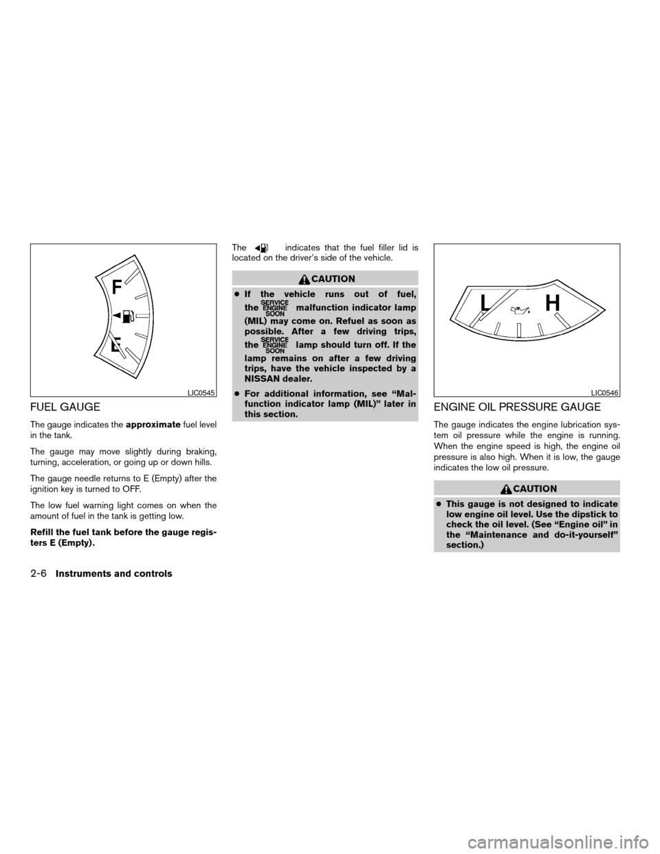
FUEL GAUGE
The gauge indicates theapproximatefuel level
in the tank.
The gauge may move slightly during braking,
turning, acceleration, or going up or down hills.
The gauge needle returns to E (Empty) after the
ignition key is turned to OFF.
The low fuel warning light comes on when the
amount of fuel in the tank is getting low.
Refill the fuel tank before the gauge regis-
ters E (Empty) .The
indicates that the fuel filler lid is
located on the driver’s side of the vehicle.
CAUTION
cIf the vehicle runs out of fuel,
the
malfunction indicator lamp
(MIL) may come on. Refuel as soon as
possible. After a few driving trips,
the
lamp should turn off. If the
lamp remains on after a few driving
trips, have the vehicle inspected by a
NISSAN dealer.
cFor additional information, see “Mal-
function indicator lamp (MIL)” later in
this section.
ENGINE OIL PRESSURE GAUGE
The gauge indicates the engine lubrication sys-
tem oil pressure while the engine is running.
When the engine speed is high, the engine oil
pressure is also high. When it is low, the gauge
indicates the low oil pressure.
CAUTION
cThis gauge is not designed to indicate
low engine oil level. Use the dipstick to
check the oil level. (See “Engine oil” in
the “Maintenance and do-it-yourself”
section.)
LIC0545LIC0546
2-6Instruments and controls
ZREVIEW COPY:Ð2004 Titan(tzw)
Owners Manual(owners)ÐUSA English(nna)
02/20/04Ðtbrooks
X
Page 75 of 328

cIf the gauge needle does not move with
the proper amount of engine oil, have
the vehicle checked by a NISSAN
dealer. Continued vehicle operation in
such a condition could cause serious
damage to the engine.
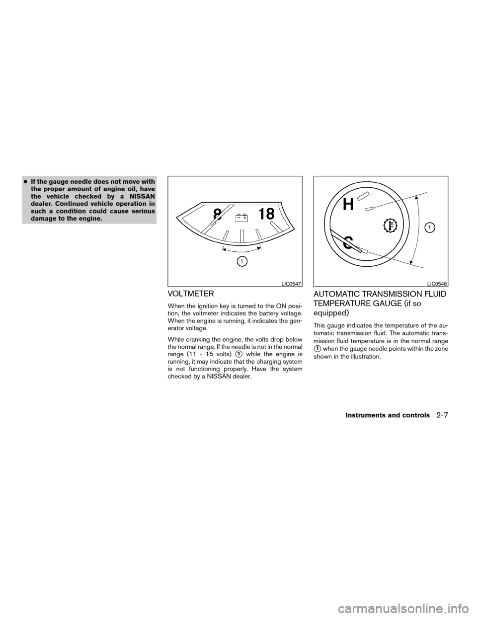
VOLTMETER
When the ignition key is turned to the ON posi-
tion, the voltmeter indicates the battery voltage.
When the engine is running, it indicates the gen-
erator voltage.
While cranking the engine, the volts drop below
the normal range. If the needle is not in the normal
range (11 - 15 volts)
s1while the engine is
running, it may indicate that the charging system
is not functioning properly. Have the system
checked by a NISSAN dealer.
AUTOMATIC TRANSMISSION FLUID
TEMPERATURE GAUGE (if so
equipped)
This gauge indicates the temperature of the au-
tomatic transmission fluid. The automatic trans-
mission fluid temperature is in the normal range
s1when the gauge needle points within the zone
shown in the illustration.
LIC0547LIC0548
Instruments and controls2-7
ZREVIEW COPY:Ð2004 Titan(tzw)
Owners Manual(owners)ÐUSA English(nna)
02/20/04Ðtbrooks
X
Page 76 of 328

CAUTION
cThis gauge is not designed to indicate
low automatic transmission fluid level.
Use the dipstick to check the fluid level.
(See “5-speed automatic transmission
fluid” in the “Maintenance and do-it-
yourself” section.)
cIf the gauge indicates automatic trans-
mission fluid temperature over the nor-
mal range, stop the vehicle as soon as
safely possible. Have the vehicle
checked by a NISSAN dealer. Contin-
ued operation of the vehicle may seri-
ously damage the transmission.This unit has the following functions:
cMeasures terrestrial magnetism and indi-
cates heading direction of vehicle
cIndicates outside air temperature
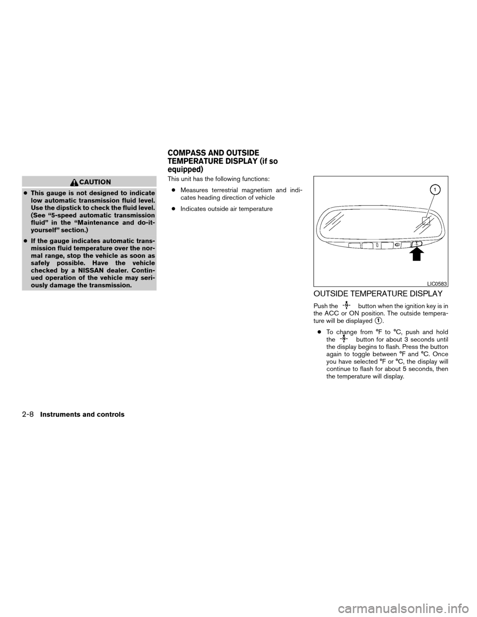
OUTSIDE TEMPERATURE DISPLAY
Push thebutton when the ignition key is in
the ACC or ON position. The outside tempera-
ture will be displayed
s1.
cTo change from °F to °C, push and hold
the
button for about 3 seconds until
the display begins to flash. Press the button
again to toggle between °F and °C. Once
you have selected °F or °C, the display will
continue to flash for about 5 seconds, then
the temperature will display.
LIC0583
COMPASS AND OUTSIDE
TEMPERATURE DISPLAY (if so
equipped)
2-8Instruments and controls
ZREVIEW COPY:Ð2004 Titan(tzw)
Owners Manual(owners)ÐUSA English(nna)
02/20/04Ðtbrooks
X
Page 77 of 328

cWhen the outside temperature is between
140°F (60°C) and 194°F (90°C) , the display
will read 140°F (60°C) . When the tempera-
ture is above 194°F (90°C) , the display will
read “SC”.
cWhen the outside temperature is between
than -40°F (-40°C) and -60°F (-51°C) , the
display will read -40°F (-40°C) . When the
temperature is below -60°F (-51°C) , the dis-
play will read “OC”.
cThe outside temperature sensor is located in
front of the radiator. The sensor may be
affected by road or engine heat, wind direc-
tion and other driving conditions. The display
may differ from the actual outside tempera-
ture or the temperature displayed on various
signs or billboards.
cTemperature display will not update unless
the vehicle is moving faster than 12 MPH
(20 km/h) , or the ignition switch has been
OFF for 4 hours.COMPASS DISPLAY
Push thebutton when the ignition key is in
the ACC or ON position to display the direction
s1.
N: north
E: east
S: south
W: west
If the display reads “CAL”, calibrate the compass
by driving the vehicle in three complete circles at
less than 5 MPH (8 km/h) .
You can also calibrate the compass by driving
your vehicle on your everyday route. The com-
pass will be calibrated once it has tracked three
complete circles.
Instruments and controls2-9
ZREVIEW COPY:Ð2004 Titan(tzw)
Owners Manual(owners)ÐUSA English(nna)
02/20/04Ðtbrooks
X
Page 80 of 328

orAnti-lock brake warning lightLow tire pressure warning light4WD shift indicator light (model)
Automatic transmission check warning lightLow windshield washer fluid warning lightorFront passenger air bag status
light
Automatic transmission park warning light
(model)Seat belt warning light and chimeHigh beam indicator light (Blue)
orBrake warning lightSupplemental air bag warning lightMalfunction indicator lamp (MIL)
Charge warning lightAutomatic transmission position indicator lightSecurity indicator light (NVIS) (if so equipped)
Door open warning lightorActive brake limited slip (if so
equipped)Slip indicator light (if so equipped)
Engine oil pressure low/engine coolant tem-
perature high warning lightCruise main switch indicator lightTransfer 4LO position indicator light
(model)
4WD warning light (model)Cruise set switch indicator lightTurn signal/hazard indicator lights
Low fuel warning lightElectronic locking rear differential system on
indicator light (if so equipped)Vehicle dynamic control off indicator light (if so
equipped)
CHECKING BULBS
With all doors closed, apply the parking brake
and turn the ignition key to the ON position
without starting the engine. The following lights
will come on:
,or,,,,
The following lights come on briefly and then go
off:
or,,,,,
,,,
If any light fails to come on, it may indicate
a burned-out bulb or an open circuit in the
electrical system. Have the system repaired
promptly.
WARNING/INDICATOR LIGHTS AND
AUDIBLE REMINDERS
2-12Instruments and controls
ZREVIEW COPY:Ð2004 Titan(tzw)
Owners Manual(owners)ÐUSA English(nna)
02/20/04Ðtbrooks
X