Page 1052 of 1833
PROPELLER SHAFT &
DIFFERENTIAL CARRIER
SECTION
PD
CONTENTS
PREPARATION ................................................................2
PROPELLER SHAFT ......................................................5
On-Vehicle Service ......................................................6
Removal and Installation .............................................7
Inspection.....................................................................7
Disassembly.................................................................7
Assembly .....................................................................8
ON-VEHICLE SERVICE ................................................10
Front Oil Seal Replacement
(Front final drive: R180A) ..........................................10
Front Oil Seal Replacement
(Rear final drive: C200) .............................................10
REMOVAL AND INSTALLATION (Front final drive
- R180A) ........................................................................\
.12
Removal .....................................................................12
Installation ..................................................................12
REMOVAL AND INSTALLATION (Rear final drive
- C200) ........................................................................\
...13
Removal .....................................................................13
Installation ..................................................................13
FRONT FINAL DRIVE (R180A) ....................................14
DISASSEMBLY (R180A) ...............................................15
Pre-inspection ............................................................15
Final Drive Housing ...................................................15
Differential Case ........................................................18
Extension Tube and Differential Side Shaft ..............19
INSPECTION (R180A) ...................................................20
Ring Gear and Drive Pinion ......................................20
Differential Case Assembly........................................20
Bearing.......................................................................20
ADJUSTMENT (R180A) ................................................21 Drive Pinion Height ....................................................21
Side Bearing Preload.................................................24
Tooth Contact.............................................................27
ASSEMBLY (R180A) .....................................................28
Extension Tube and Differential Side Shaft ..............28
Differential Case ........................................................29
Final Drive Housing ...................................................30
REAR FINAL DRIVE (C200) .........................................35
Air Breather................................................................36
DISASSEMBLY (C200) ..................................................37
Pre-inspection ............................................................37
Differential Carrier......................................................38
Differential Case ........................................................40
INSPECTION (C200) .....................................................42
Ring Gear and Drive Pinion ......................................42
Differential Case Assembly........................................42
Bearing.......................................................................42
LIMITED SLIP DIFFERENTIAL (C200) .........................43
Preparation for Disassembly .....................................43
Disassembly...............................................................44
Inspection...................................................................44
Adjustment .................................................................45
Assembly ...................................................................47
ADJUSTMENT (C200) ...................................................49
Drive Pinion Height ....................................................49
Tooth Contact.............................................................52
ASSEMBLY (C200) ........................................................53
Differential Carrier......................................................53
SERVICE DATA AND SPECIFICATIONS (SDS) ..........57
Propeller Shaft ...........................................................57
Final Drive..................................................................58
http://vnx.su/
Page 1072 of 1833
To avoid confusion while calculating bearing shims, it is absolutely
necessary to stay with the metric system. If you measure anything
in inches, the results MUST be converted to the metric system.
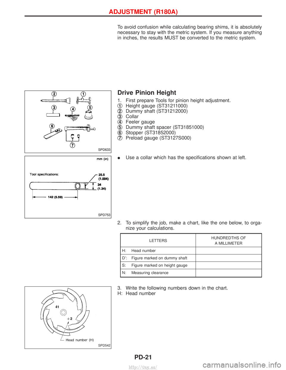
Drive Pinion Height
1. First prepare Tools for pinion height adjustment.
q
1Height gauge (ST31211000)
q
2Dummy shaft (ST31212000)
q
3Collar
q
4Feeler gauge
q
5Dummy shaft spacer (ST31851000)
q
6Stopper (ST31852000)
q
7Preload gauge (ST3127S000)
I Use a collar which has the specifications shown at left.
2. To simplify the job, make a chart, like the one below, to orga- nize your calculations.
LETTERS HUNDREDTHS OF
A MILLIMETER
H: Head number
D¢ : Figure marked on dummy shaft
S: Figure marked on height gauge
N: Measuring clearance
3. Write the following numbers down in the chart.
H: Head number
SPD633
SPD753
SPD542
ADJUSTMENT (R180A)
PD-21
http://vnx.su/
Page 1073 of 1833
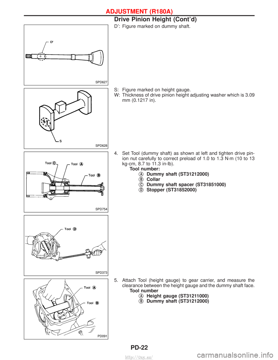
D¢: Figure marked on dummy shaft.
S: Figure marked on height gauge.
W: Thickness of drive pinion height adjusting washer which is 3.09 mm (0.1217 in).
4. Set Tool (dummy shaft) as shown at left and tighten drive pin- ion nut carefully to correct preload of 1.0 to 1.3 N ×m (10 to 13
kg-cm, 8.7 to 11.3 in-lb). Tool number: q
ADummy shaft (ST31212000)
q
BCollar
q
CDummy shaft spacer (ST31851000)
q
DStopper (ST31852000)
5. Attach Tool (height gauge) to gear carrier, and measure the clearance between the height gauge and the dummy shaft face.Tool number q
AHeight gauge (ST31211000)
q
BDummy shaft (ST31212000)
SPD627
SPD628
SPD754
SPD373
PD091
ADJUSTMENT (R180A)
Drive Pinion Height (Cont'd)
PD-22
http://vnx.su/
Page 1074 of 1833
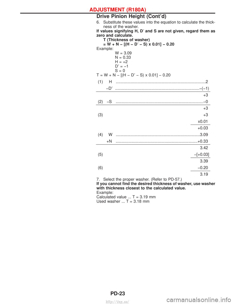
6. Substitute these values into the equation to calculate the thick-ness of the washer.
If values signifying H, D¢ and S are not given, regard them as
zero and calculate. T (Thickness of washer)
=W+Nþ[(HþD ¢þ S) x 0.01] þ 0.20
Example: W = 3.09
N = 0.33
H=+2
D¢=þ1
S=0
T=W+Nþ[(HþD ¢þ S) x 0.01] þ 0.20
(1) H ........................................................................\
.......2
þD¢ ........................................................................\
..þ(þ1)
+3
(2) þS ........................................................................\
.....þ0 +3
(3) +3 x0.01
+0.03
(4) W ........................................................................\
..3.09 +N ........................................................................\
+0.33 3.42
(5) þ[+0.03] 3.39
(6) þ0.20 3.19
7. Select the proper washer. (Refer to PD-57.)
If you cannot find the desired thickness of washer, use washer
with thickness closest to the calculated value.
Example:
Calculated value ... T = 3.19 mm
Used washer ... T = 3.18 mm
ADJUSTMENT (R180A)
Drive Pinion Height (Cont'd)
PD-23
http://vnx.su/
Page 1081 of 1833
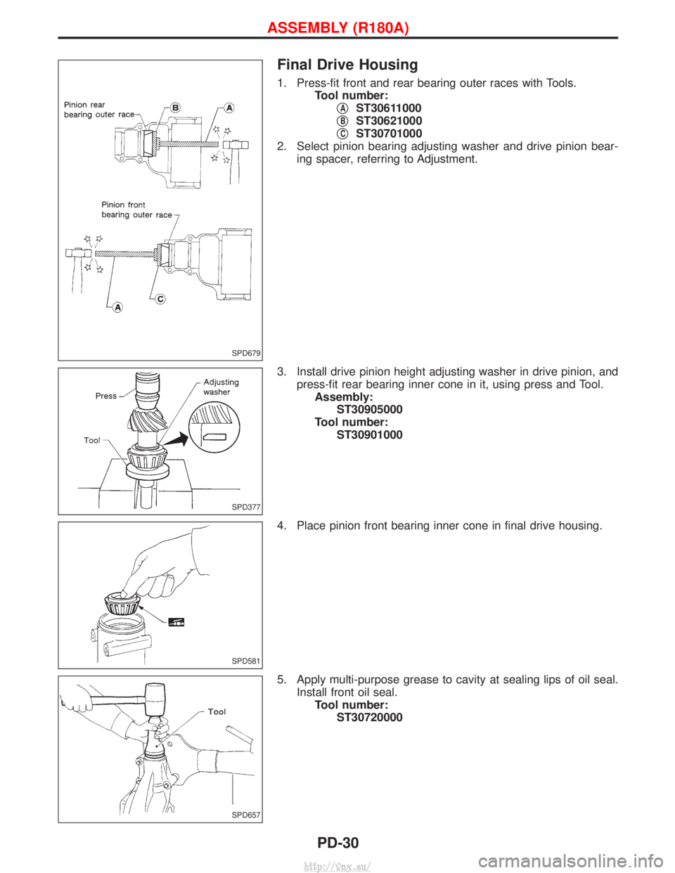
Final Drive Housing
1. Press-fit front and rear bearing outer races with Tools.Tool number:q
AST30611000
q
BST30621000
q
CST30701000
2. Select pinion bearing adjusting washer and drive pinion bear- ing spacer, referring to Adjustment.
3. Install drive pinion height adjusting washer in drive pinion, and press-fit rear bearing inner cone in it, using press and Tool.Assembly: ST30905000
Tool number: ST30901000
4. Place pinion front bearing inner cone in final drive housing.
5. Apply multi-purpose grease to cavity at sealing lips of oil seal. Install front oil seal.Tool number: ST30720000
SPD679
SPD377
SPD581
SPD657
ASSEMBLY (R180A)
PD-30
http://vnx.su/
Page 1100 of 1833
To avoid confusion while calculating bearing shims, it is absolutely
necessary to stay with the metric system. If you measure anything
in inches, the results MUST be converted to the metric system.
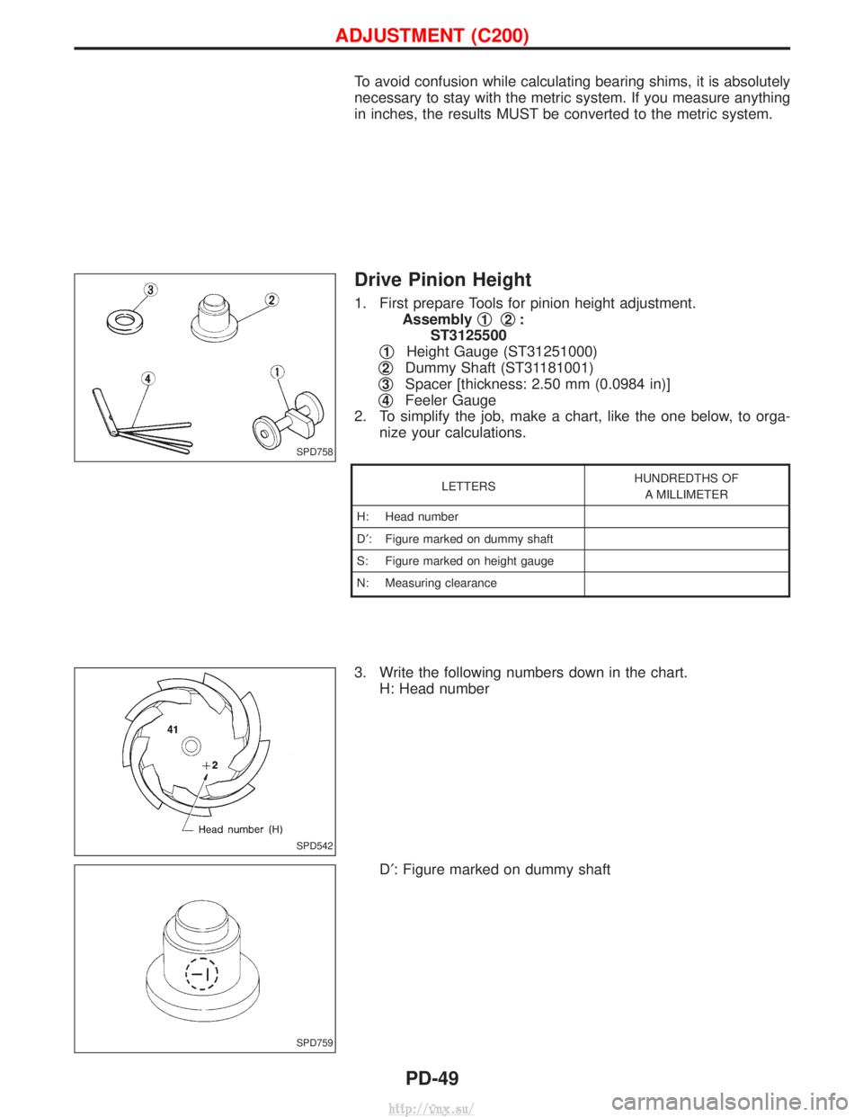
Drive Pinion Height
1. First prepare Tools for pinion height adjustment.Assembly q
1q2:
ST3125500
q
1Height Gauge (ST31251000)
q
2Dummy Shaft (ST31181001)
q
3Spacer [thickness: 2.50 mm (0.0984 in)]
q
4Feeler Gauge
2. To simplify the job, make a chart, like the one below, to orga- nize your calculations.
LETTERS HUNDREDTHS OF
A MILLIMETER
H: Head number
D¢ : Figure marked on dummy shaft
S: Figure marked on height gauge
N: Measuring clearance
3. Write the following numbers down in the chart. H: Head number
D¢: Figure marked on dummy shaft
SPD758
SPD542
SPD759
ADJUSTMENT (C200)
PD-49
http://vnx.su/
Page 1101 of 1833
S: Figure marked on height gauge
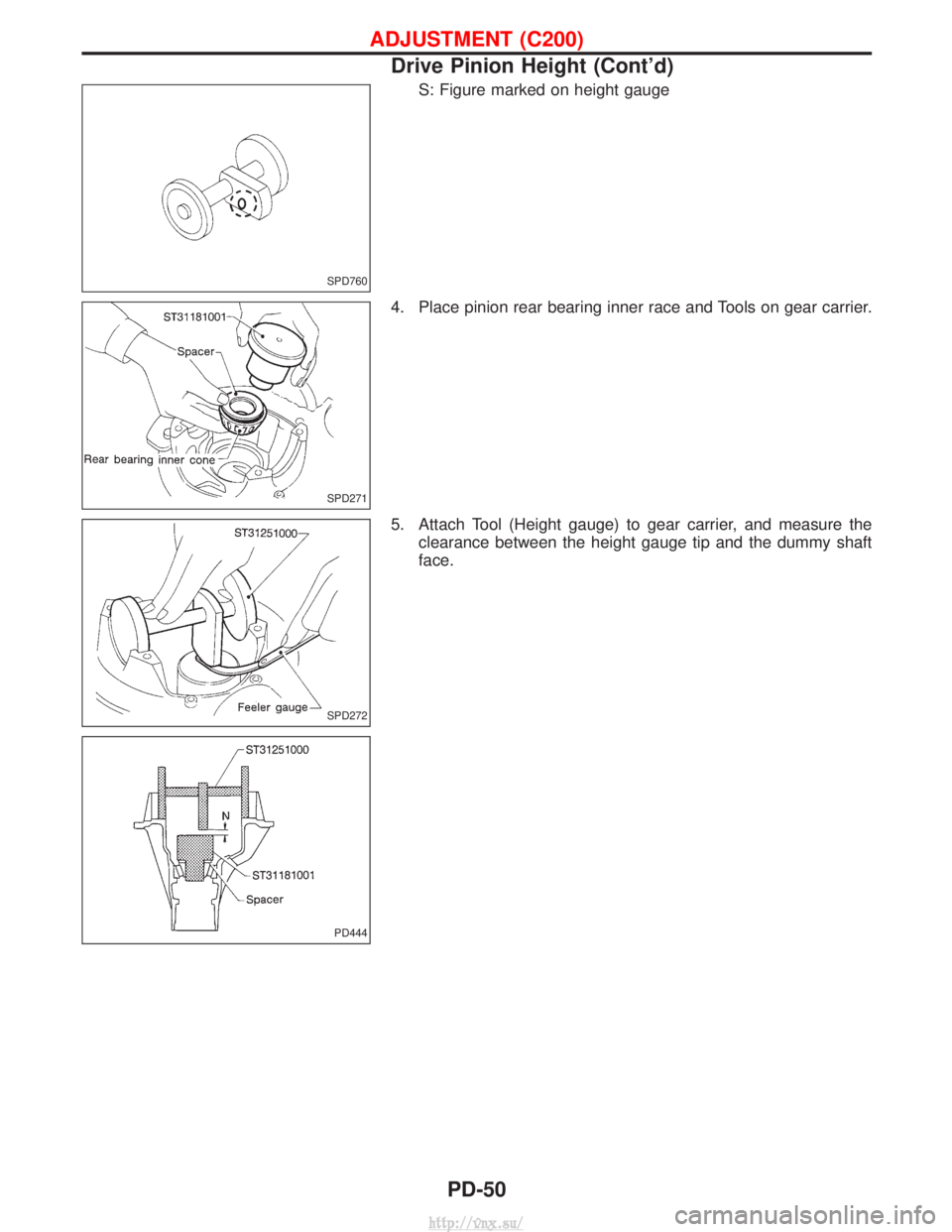
4. Place pinion rear bearing inner race and Tools on gear carrier.
5. Attach Tool (Height gauge) to gear carrier, and measure the clearance between the height gauge tip and the dummy shaft
face.
SPD760
SPD271
SPD272
PD444
ADJUSTMENT (C200)
Drive Pinion Height (Cont'd)
PD-50
http://vnx.su/
Page 1102 of 1833
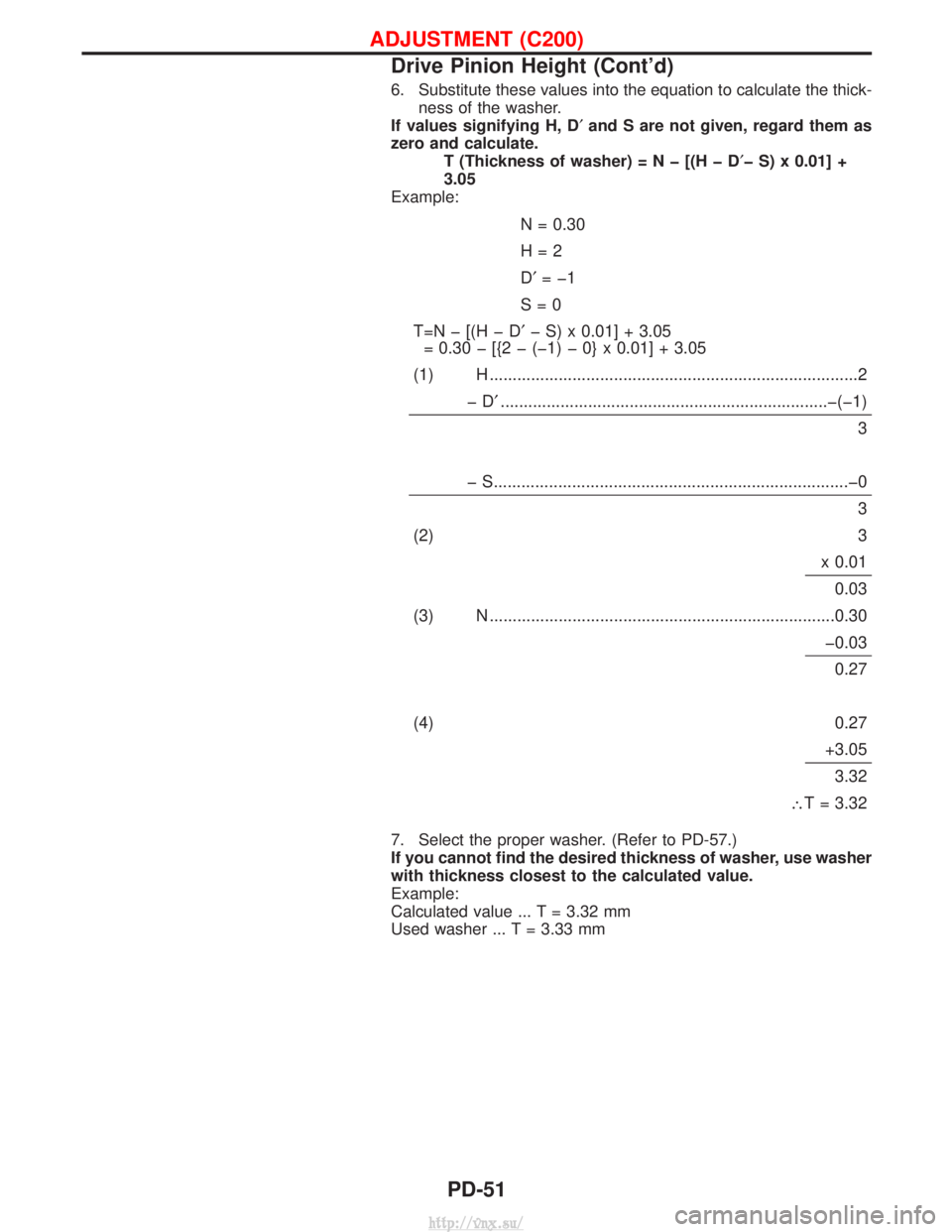
6. Substitute these values into the equation to calculate the thick-ness of the washer.
If values signifying H, D¢ and S are not given, regard them as
zero and calculate. T (Thickness of washer)=Nþ[(HþD ¢þ S) x 0.01] +
3.05
Example:
N = 0.30
H=2
D¢ =þ1
S=0
T=Nþ[(HþD ¢þ S) x 0.01] + 3.05
= 0.30 þ [{2 þ (þ1) þ 0} x 0.01] + 3.05
(1) H ........................................................................\
........2 þD¢.......................................................................þ\
(þ1)
3
þ S........................................................................\
.....þ0 3
(2) 3 x 0.010.03
(3) N ........................................................................\
...0.30 þ0.030.27
(4) 0.27 +3.053.32
\ T = 3.32
7. Select the proper washer. (Refer to PD-57.)
If you cannot find the desired thickness of washer, use washer
with thickness closest to the calculated value.
Example:
Calculated value ... T = 3.32 mm
Used washer ... T = 3.33 mm
ADJUSTMENT (C200)
Drive Pinion Height (Cont'd)
PD-51
http://vnx.su/