2004 NISSAN TERRANO alternator
[x] Cancel search: alternatorPage 197 of 1833
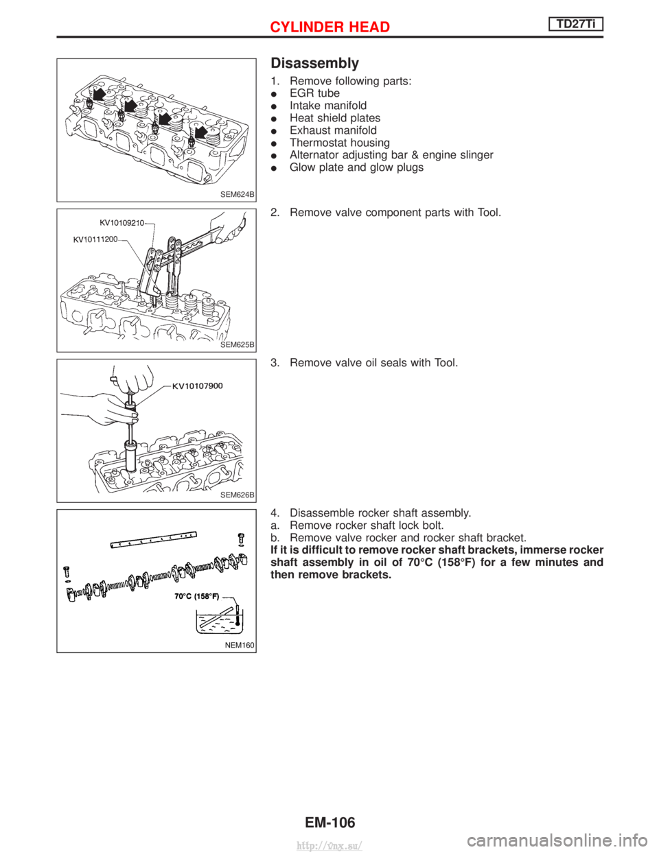
Disassembly
1. Remove following parts:
IEGR tube
I Intake manifold
I Heat shield plates
I Exhaust manifold
I Thermostat housing
I Alternator adjusting bar & engine slinger
I Glow plate and glow plugs
2. Remove valve component parts with Tool.
3. Remove valve oil seals with Tool.
4. Disassemble rocker shaft assembly.
a. Remove rocker shaft lock bolt.
b. Remove valve rocker and rocker shaft bracket.
If it is difficult to remove rocker shaft brackets, immerse rocker
shaft assembly in oil of 70ÉC (158ÉF) for a few minutes and
then remove brackets.
SEM624B
SEM625B
SEM626B
NEM160
CYLINDER HEADTD27Ti
EM-106
http://vnx.su/
Page 1464 of 1833
STARTING & CHARGING SYSTEMSSECTION
SC
CONTENTS
PRECAUTIONS ...............................................................2
Supplemental Restraint System (SRS) ²AIR
BAG² and²SEAT BELT PRE-TENSIONER² ...............2
Wiring Diagrams and Trouble Diagnoses....................2
BATTERY ........................................................................\
.3
How to Handle Battery ................................................3
Battery Test and Charging Chart .................................6
STARTING SYSTEM .....................................................13
System Description ....................................................13
Wiring Diagram - START -.........................................14
Trouble Diagnoses.....................................................16
Construction ...............................................................17
Magnetic Switch Check .............................................19
Pinion/Clutch Check ..................................................19
Brush Check ..............................................................20 Field Coil Check ........................................................20
Armature Check .........................................................21
Assembly ...................................................................22
CHARGING SYSTEM ....................................................23
System Description ....................................................23
Wiring Diagram - CHARGE -.....................................24
Trouble Diagnoses.....................................................26
Construction ...............................................................27
Disassembly...............................................................28
Inspection...................................................................28
Assembly ...................................................................29
SERVICE DATA AND SPECIFICATIONS (SDS) ..........30
Battery........................................................................\
30
Starter ........................................................................\
30
Alternator ...................................................................30
http://vnx.su/
Page 1486 of 1833
System Description
The alternator provides DC voltage to operate the vehicle's electrical system and to keep the battery charged.
The voltage output is controlled by the IC regulator.
Power is supplied at all times to alternator terminal 4 (S) (ZD30DDTi engine models) through:
I10A fuse (No. 31, located in the fuse and fusible link box).
Terminal B supplies power to charge the battery and operate the vehicle's electrical system. Output voltage
is controlled by the IC regulator at terminal 4 (S) detecting the input voltage (ZD30DDTi engine models). The
charging circuit is protected by the 100A fusible link.
The alternator is grounded to the engine block.
With the ignition switch in the ON or START position, power is supplied
I through 10A fuse [No. 12, located in the fuse block (J/B)]
I to combination meter terminal 28 for the charge warning lamp.
Ground is supplied to terminal 2 of the combination meter through terminal 1(L) (TD27Ti engine models) or
3(L) (ZD30DDTi engine models) of the alternator. With power and ground supplied, the charge warning lamp
will illuminate. When the alternator is providing sufficient voltage with the engine running, the ground is opened
and the charge warning lamp will go off.
If the charge warning lamp illuminates with the engine running, a malfunction is indicated.
CHARGING SYSTEM
SC-23
http://vnx.su/
Page 1489 of 1833
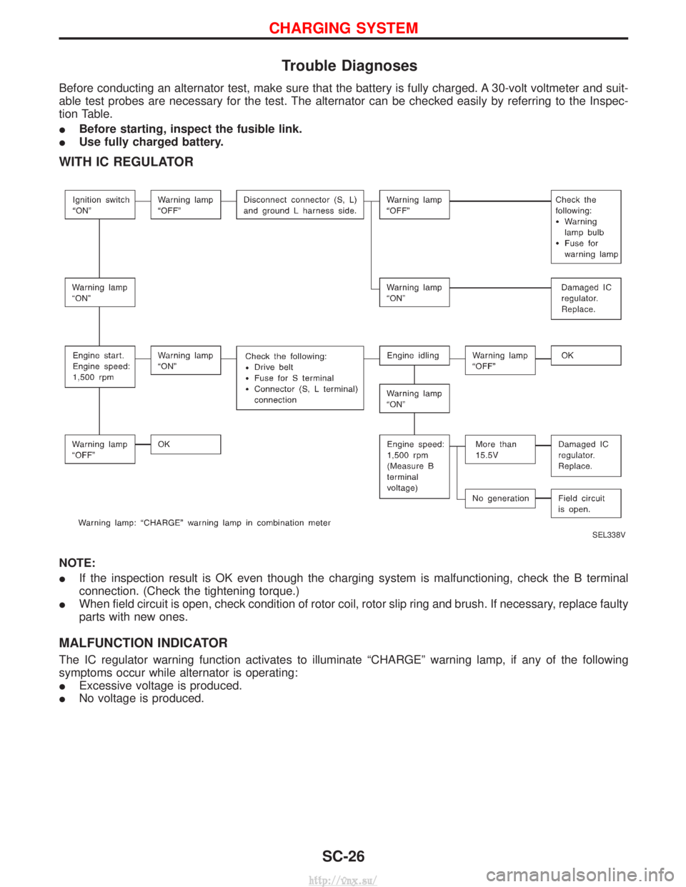
Trouble Diagnoses
Before conducting an alternator test, make sure that the battery is fully charged. A 30-volt voltmeter and suit-
able test probes are necessary for the test. The alternator can be checked easily by referring to the Inspec-
tion Table.
IBefore starting, inspect the fusible link.
I Use fully charged battery.
WITH IC REGULATOR
NOTE:
IIf the inspection result is OK even though the charging system is malfunctioning, check the B terminal
connection. (Check the tightening torque.)
I When field circuit is open, check condition of rotor coil, rotor slip ring and brush. If necessary, replace faulty
parts with new ones.
MALFUNCTION INDICATOR
The IC regulator warning function activates to illuminate ªCHARGEº warning lamp, if any of the following
symptoms occur while alternator is operating:
IExcessive voltage is produced.
I No voltage is produced.
SEL338V
CHARGING SYSTEM
SC-26
http://vnx.su/
Page 1493 of 1833
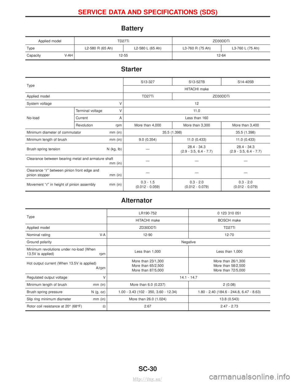
Battery
Applied modelTD27Ti ZD30DDTi
Type L2-580 R (65 Ah)L2-580 L (65 Ah)L3-760 R (75 Ah) L3-760 L (75 Ah)
Capacity V-AH 12-55 12-64
Starter
Type S13-327 S13-527B S14-405B
HITACHI make
Applied model TD27Ti ZD30DDTi
System voltage V 12
No-load Terminal voltage V 11.0
Current A Less than 160
Revolution rpm More than 4,000 More than 3,300 More than 3,400
Minimum diameter of commutator mm (in) 35.5 (1.398) 35.5 (1.398)
Minimum length of brush mm (in) 9.0 (0.354) 11.0 (0.433) 11.0 (0.433)
Brush spring tension N (kg, lb) Ð 28.4 - 34.3
(2.9 - 3.5, 6.4 - 7.7) 28.4 - 34.3
(2.9 - 3.5, 6.4 - 7.7)
Clearance between bearing metal and armature shaft mm (in)ÐÐÐ
Clearance ªº between pinion front edge and
pinion stopper mm (in) ÐÐÐ
Movement ªº in height of pinion assembly mm (in) 0.3 - 1.5
(0.012 - 0.059) 0.3 - 2.0
(0.012 - 0.079) 0.3 - 2.0
(0.012 - 0.079)
Alternator
Type LR190-752 0 123 310 051
HITACHI make BOSCH make
Applied model ZD30DDTi TD27Ti
Nominal rating V-A 12-90 12-70
Ground polarity Negative
Minimum revolutions under no-load (When
13.5V is applied) rpm Less than 1,000 Less than 1,000
Hot output current (When 13.5V is applied) A/rpmMore than 23/1,300
More than 65/2,500
More than 87/5,000 More than 26/1,300
More than 58/2,500
More than 72/5,000
Regulated output voltage V 14.1 - 14.7
Minimum length of brush mm (in) More than 6.0 (0.237) 2 (0.08)
Brush spring pressure N (g, oz) 1.00 - 3.43 (102 - 350, 3.60 - 12.34) 1.80 - 2.40 (184.6 - 244.8, 6.47 - 8.63)
Slip ring minimum diameter mm (in) More than 26.0 (1.024) 13.8 (0.543)
Rotor coil resistance at 20É (68ÉF) W2.67 2.47 - 2.73
SERVICE DATA AND SPECIFICATIONS (SDS)
SC-30
http://vnx.su/
Page 1516 of 1833
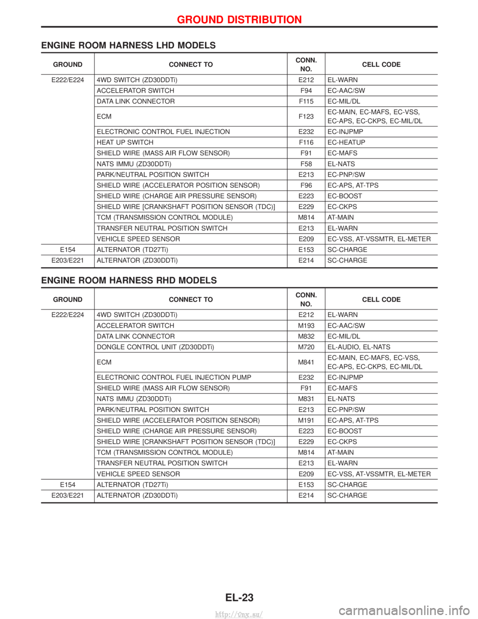
ENGINE ROOM HARNESS LHD MODELS
GROUNDCONNECT TO CONN.
NO. CELL CODE
E222/E224 4WD SWITCH (ZD30DDTi) E212 EL-WARN
ACCELERATOR SWITCH F94 EC-AAC/SW
DATA LINK CONNECTOR F115 EC-MIL/DL
ECM F123EC-MAIN, EC-MAFS, EC-VSS,
EC-APS, EC-CKPS, EC-MIL/DL
ELECTRONIC CONTROL FUEL INJECTION E232 EC-INJPMP
HEAT UP SWITCH F116 EC-HEATUP
SHIELD WIRE (MASS AIR FLOW SENSOR) F91 EC-MAFS
NATS IMMU (ZD30DDTi) F58 EL-NATS
PARK/NEUTRAL POSITION SWITCH E213 EC-PNP/SW
SHIELD WIRE (ACCELERATOR POSITION SENSOR) F96 EC-APS, AT-TPS
SHIELD WIRE (CHARGE AIR PRESSURE SENSOR) E223 EC-BOOST
SHIELD WIRE [CRANKSHAFT POSITION SENSOR (TDC)] E229 EC-CKPS
TCM (TRANSMISSION CONTROL MODULE) M814 AT-MAIN
TRANSFER NEUTRAL POSITION SWITCH E213 EL-WARN
VEHICLE SPEED SENSOR E209 EC-VSS, AT-VSSMTR, EL-METER
E154 ALTERNATOR (TD27Ti) E153 SC-CHARGE
E203/E221 ALTERNATOR (ZD30DDTi) E214 SC-CHARGE
ENGINE ROOM HARNESS RHD MODELS
GROUNDCONNECT TO CONN.
NO. CELL CODE
E222/E224 4WD SWITCH (ZD30DDTi) E212 EL-WARN
ACCELERATOR SWITCH M193 EC-AAC/SW
DATA LINK CONNECTOR M832 EC-MIL/DL
DONGLE CONTROL UNIT (ZD30DDTi) M720 EL-AUDIO, EL-NATS
ECM M841EC-MAIN, EC-MAFS, EC-VSS,
EC-APS, EC-CKPS, EC-MIL/DL
ELECTRONIC CONTROL FUEL INJECTION PUMP E232 EC-INJPMP
SHIELD WIRE (MASS AIR FLOW SENSOR) F91 EC-MAFS
NATS IMMU (ZD30DDTi) M831 EL-NATS
PARK/NEUTRAL POSITION SWITCH E213 EC-PNP/SW
SHIELD WIRE (ACCELERATOR POSITION SENSOR) M191 EC-APS, AT-TPS
SHIELD WIRE (CHARGE AIR PRESSURE SENSOR) E223 EC-BOOST
SHIELD WIRE [CRANKSHAFT POSITION SENSOR (TDC)] E229 EC-CKPS
TCM (TRANSMISSION CONTROL MODULE) M814 AT-MAIN
TRANSFER NEUTRAL POSITION SWITCH E213 EL-WARN
VEHICLE SPEED SENSOR E209 EC-VSS, AT-VSSMTR, EL-METER
E154 ALTERNATOR (TD27Ti) E153 SC-CHARGE
E203/E221 ALTERNATOR (ZD30DDTi) E214 SC-CHARGE
GROUND DISTRIBUTION
EL-23
http://vnx.su/
Page 1525 of 1833
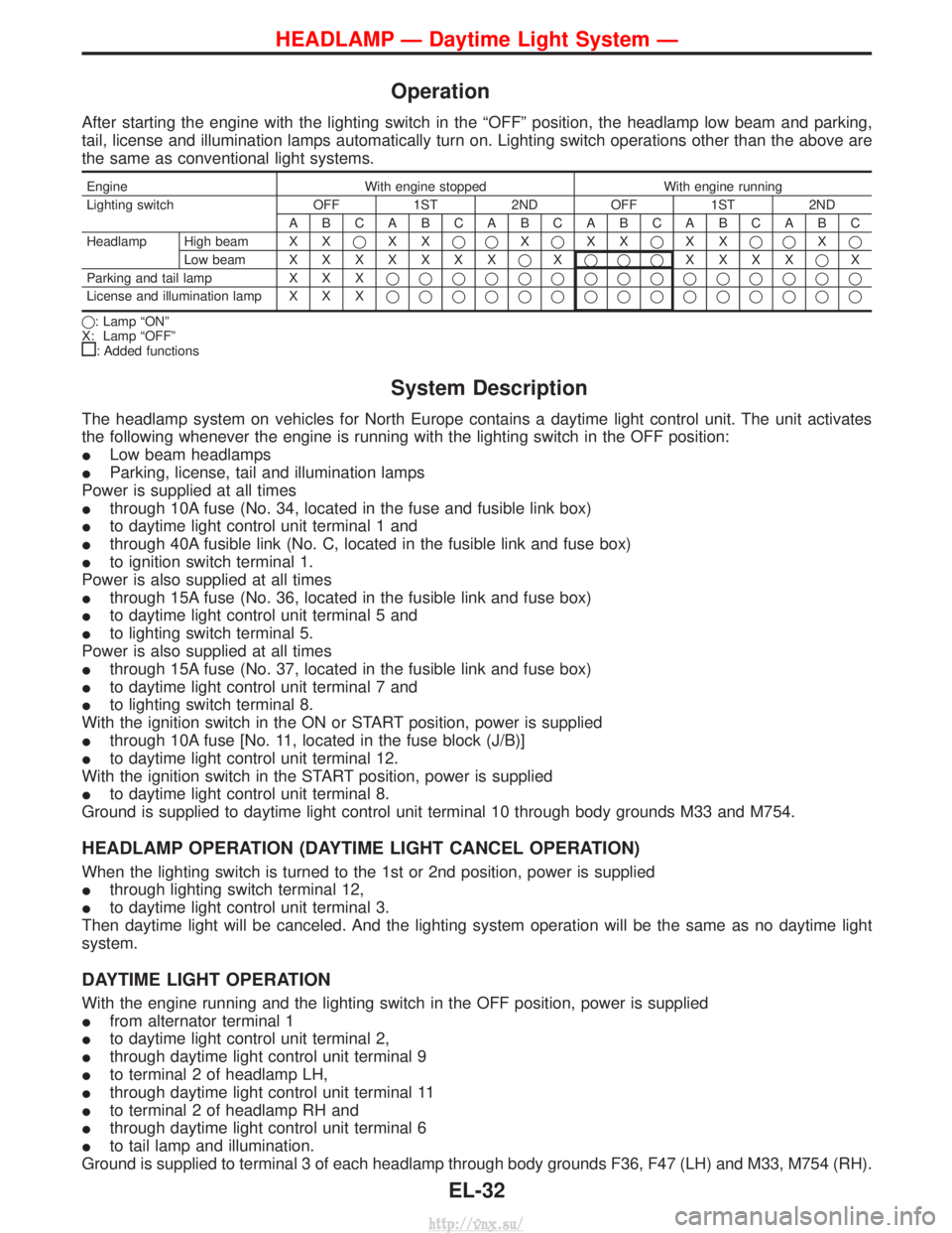
Operation
After starting the engine with the lighting switch in the ªOFFº position, the headlamp low beam and parking,
tail, license and illumination lamps automatically turn on. Lighting switch operations other than the above are
the same as conventional light systems.
EngineWith engine stopped With engine running
Lighting switch OFF 1ST 2ND OFF 1ST 2ND ABCABCABCABCABCABC
Headlamp High beam X X qXX qq Xq XX qXX qq Xq
Low beam XXXXXXX qXqqq XXXX qX
Parking and tail lamp X X Xqqqqqqqqqqqqqqq
License and illumination lamp X X X qqqqqqqqqqqqqqq
q: Lamp ªONº
X: Lamp ªOFFº
: Added functions
System Description
The headlamp system on vehicles for North Europe contains a daytime light control unit. The unit activates
the following whenever the engine is running with the lighting switch in the OFF position:
I Low beam headlamps
I Parking, license, tail and illumination lamps
Power is supplied at all times
I through 10A fuse (No. 34, located in the fuse and fusible link box)
I to daytime light control unit terminal 1 and
I through 40A fusible link (No. C, located in the fusible link and fuse box)
I to ignition switch terminal 1.
Power is also supplied at all times
I through 15A fuse (No. 36, located in the fusible link and fuse box)
I to daytime light control unit terminal 5 and
I to lighting switch terminal 5.
Power is also supplied at all times
I through 15A fuse (No. 37, located in the fusible link and fuse box)
I to daytime light control unit terminal 7 and
I to lighting switch terminal 8.
With the ignition switch in the ON or START position, power is supplied
I through 10A fuse [No. 11, located in the fuse block (J/B)]
I to daytime light control unit terminal 12.
With the ignition switch in the START position, power is supplied
I to daytime light control unit terminal 8.
Ground is supplied to daytime light control unit terminal 10 through body grounds M33 and M754.
HEADLAMP OPERATION (DAYTIME LIGHT CANCEL OPERATION)
When the lighting switch is turned to the 1st or 2nd position, power is supplied
I through lighting switch terminal 12,
I to daytime light control unit terminal 3.
Then daytime light will be canceled. And the lighting system operation will be the same as no daytime light
system.
DAYTIME LIGHT OPERATION
With the engine running and the lighting switch in the OFF position, power is supplied
I from alternator terminal 1
I to daytime light control unit terminal 2,
I through daytime light control unit terminal 9
I to terminal 2 of headlamp LH,
I through daytime light control unit terminal 11
I to terminal 2 of headlamp RH and
I through daytime light control unit terminal 6
I to tail lamp and illumination.
Ground is supplied to terminal 3 of each headlamp through body grounds F36, F47 (LH) and M33, M754 (RH).
HEADLAMP Ð Daytime Light System Ð
EL-32
http://vnx.su/
Page 1533 of 1833
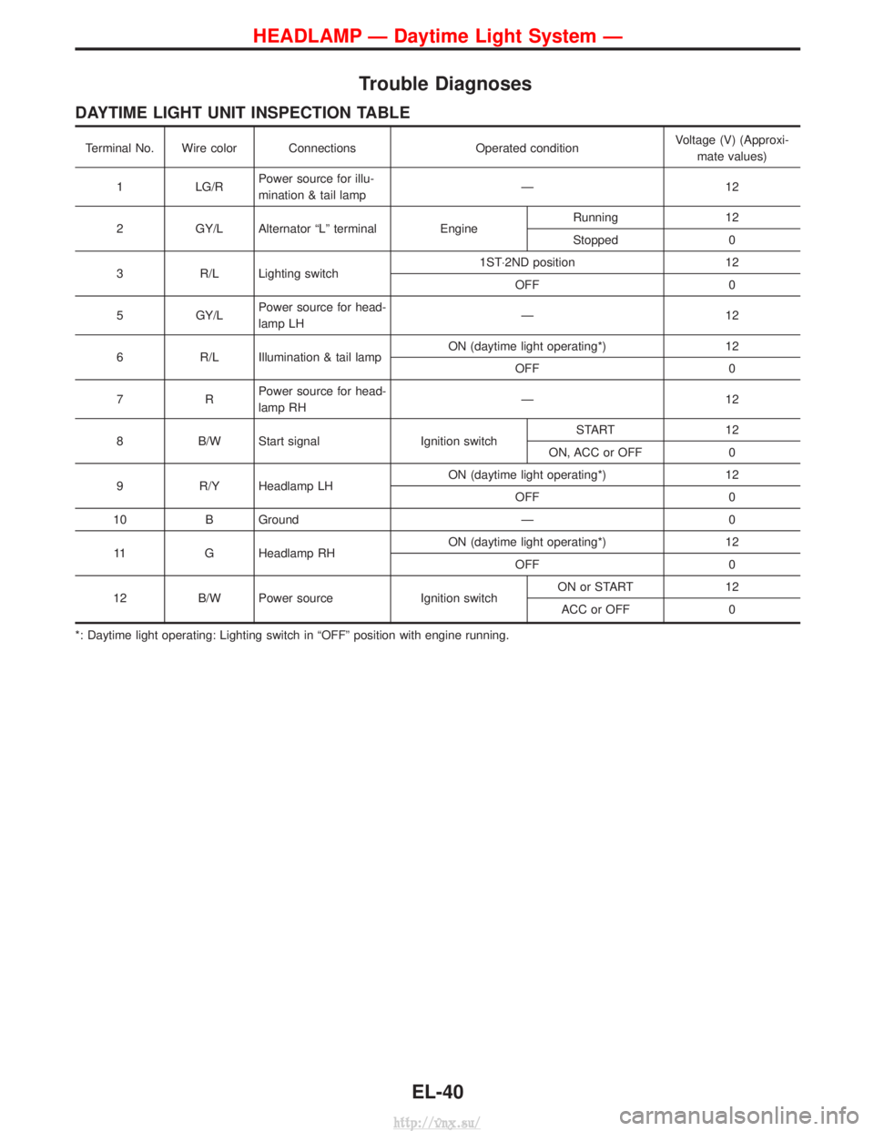
Trouble Diagnoses
DAYTIME LIGHT UNIT INSPECTION TABLE
Terminal No. Wire color ConnectionsOperated conditionVoltage (V) (Approxi-
mate values)
1 LG/RPower source for illu-
mination & tail lamp Ð1
2
2 GY/L Alternator ªLº terminal EngineRunning
12
Stopped 0
3 R/L Lighting switch 1ST×2ND position
12
OFF 0
5 GY/LPower source for head-
lamp LH Ð1
2
6 R/L Illumination & tail lamp ON (daytime light operating*)
12
OFF 0
7R Power source for head-
lamp RH Ð1
2
8 B/W Start signal Ignition switchSTART
12
ON, ACC or OFF 0
9 R/Y Headlamp LH ON (daytime light operating*)
12
OFF 0
10 B Ground Ð0
11 G Headlamp RH ON (daytime light operating*)
12
OFF 0
12 B/W Power source Ignition switchON or START
12
ACC or OFF 0
*: Daytime light operating: Lighting switch in ªOFFº position with engine running.
HEADLAMP Ð Daytime Light System Ð
EL-40
http://vnx.su/