2004 NISSAN SENTRA spare tire
[x] Cancel search: spare tirePage 203 of 248

Tire and loading information label (for
US)
s1Seating capacity: The maximum number of
occupants that should be seated in the ve-
hicle.
s2Vehicle load limit: See loading information in
the Technical and consumer information
section.
s3Original tire size: The size of the tires origi-
nally installed on the vehicle at the factory.
s4Recommended cold tire inflation pressure:
Inflate the tires to this pressure when the
tires are cold. Tires are considered COLD
after the vehicle has been parked for 3 or
more hours, or driven less than 1 mile (1.6
km) at moderate speeds. The recommended
cold tire inflation is set by the manufacturer
to provide the best tire wear and vehicle
handling characteristics based on the ve-
hicles GVWR.
s5Tire size – refer to “Tire labeling” later in this
section.
s6ands7Spare tire size or compact spare tire
size (if so equipped) .
type b
LDI0427
Maintenance and do-it-yourself8-41
ZREVIEW COPY:Ð2004 Sentra(b15)
Owners Manual(owners)ÐUSA English(nna)
03/18/04Ðtbrooks
X
Page 204 of 248

Checking tire pressure
1. Remove the valve stem cap from the tire.
2. Press the pressure gauge squarely onto the
valve stem. Do not press too hard or force
the valve stem sideways, or air will escape. If
the hissing of air escaping from the tire is
heard while checking the pressure, reposi-
tion the gauge to eliminate this leakage.
3. Remove the gauge.
4. Read the tire pressure on the gauge stem
and compare to the specification shown on
the Tire and Loading Information label.5. Add air to the tire as needed. If too much air
is added, press the core of the valve stem
briefly with the tip of the gauge stem to
release pressure. Recheck the pressure and
add or release air as needed.
6. Install the valve stem cap.
7. Check the pressure of all other tires, includ-
ing the spare.
Size Cold Tire Infla-
tion Pressure
Front
Original TireP195/60/R15
P195/55/R16
P215/45/ZR17230 kPa, 33 PSI
230 kPa, 33 PSI
230 kPa, 33 PSI
Rear
Original TireP195/60/R15
P195/55/R16
P215/45/ZR17210 kPa, 30 PSI
210 kPa, 30 PSI
230 kPa, 33 PSI
Spare Tire T115/70*14
T125/70*15
T135/90*15
T135/70*17420 kPa, 60 PSI
*: “R” or “D” depending on tire manufacturer.
TIRE LABELING
Federal law requires tire manufacturers to place
standardized information on the sidewall of all
tires. This information identifies and describes
the fundamental characteristics of the tire and
also provides the tire identification number (TIN)
for safety standard certification. The TIN can be
used to identify the tire in case of a recall.
LDI0393WDI0394
8-42Maintenance and do-it-yourself
ZREVIEW COPY:Ð2004 Sentra(b15)
Owners Manual(owners)ÐUSA English(nna)
03/18/04Ðtbrooks
X
Page 208 of 248
use of a winter traction device (tire chains or
cables) . The minimum clearances are determined
using the factory equipped tires. Other types may
damage your vehicle. Use chain tensioners when
recommended by the tire chain manufacturer to
ensure a tight fit. Loose end links of the tire chain
must be secured or removed to prevent the pos-
sibility of whipping action damage to the fenders
or underbody. If possible, avoid fully loading your
vehicle when using tire chains. In addition, drive
at a reduced speed. Otherwise, your vehicle may
be damaged and/or vehicle handling and perfor-
mance may be adversely affected.
Tire chains must be installed only on the
front wheels and not on the rear wheels.
Never install tire chains on a TEMPORARY USE
ONLY spare tire.
Do not use tire chains on dry roads. Driving with
chains in such conditions can cause damage to
the various mechanisms of the vehicle due to
some overstress.
CHANGING WHEELS AND TIRES
Tire rotation
NISSAN recommends rotating the tires every
7,500 miles (12,000 km) .
See “Flat tire” in the “In case of emergency”
section of this manual for tire replacing proce-
dures.
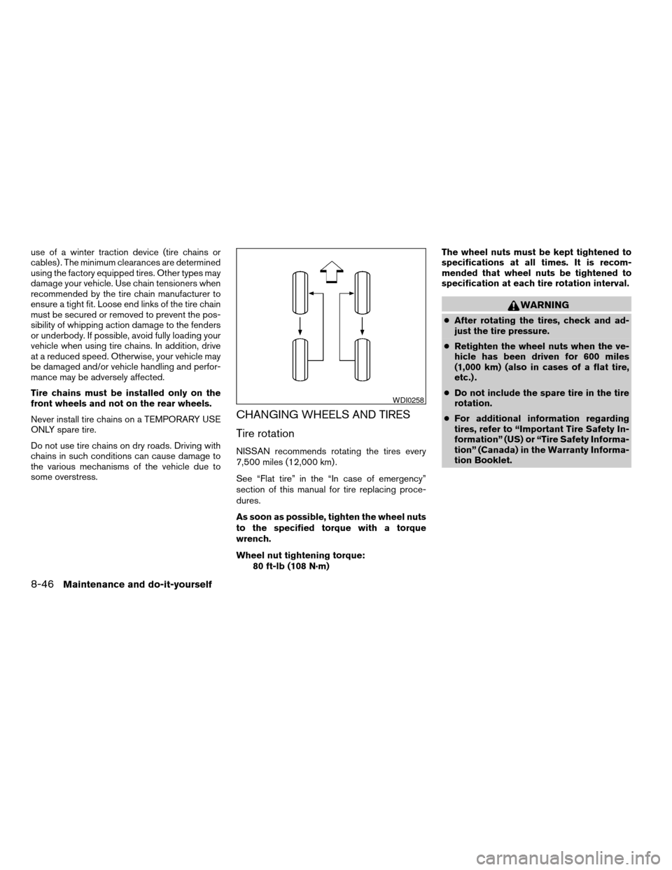
As soon as possible, tighten the wheel nuts
to the specified torque with a torque
wrench.
Wheel nut tightening torque:
80 ft-lb (108 N·m)The wheel nuts must be kept tightened to
specifications at all times. It is recom-
mended that wheel nuts be tightened to
specification at each tire rotation interval.
WARNING
cAfter rotating the tires, check and ad-
just the tire pressure.
cRetighten the wheel nuts when the ve-
hicle has been driven for 600 miles
(1,000 km) (also in cases of a flat tire,
etc.) .
cDo not include the spare tire in the tire
rotation.
cFor additional information regarding
tires, refer to “Important Tire Safety In-
formation” (US) or “Tire Safety Informa-
tion” (Canada) in the Warranty Informa-
tion Booklet.
WDI0258
8-46Maintenance and do-it-yourself
ZREVIEW COPY:Ð2004 Sentra(b15)
Owners Manual(owners)ÐUSA English(nna)
03/18/04Ðtbrooks
X
Page 209 of 248
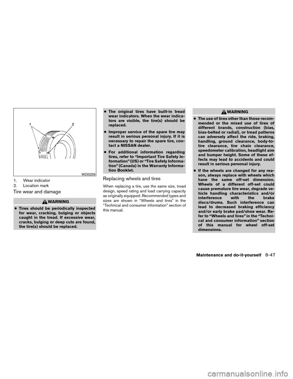
1. Wear indicator
2. Location mark
Tire wear and damage
WARNING
cTires should be periodically inspected
for wear, cracking, bulging or objects
caught in the tread. If excessive wear,
cracks, bulging or deep cuts are found,
the tire(s) should be replaced.cThe original tires have built-in tread
wear indicators. When the wear indica-
tors are visible, the tire(s) should be
replaced.
cImproper service of the spare tire may
result in serious personal injury. If it is
necessary to repair the spare tire, con-
tact a NISSAN dealer.
cFor additional information regarding
tires, refer to “Important Tire Safety In-
formation” (US) or “Tire Safety Informa-
tion” (Canada) in the Warranty Informa-
tion Booklet.
Replacing wheels and tires
When replacing a tire, use the same size, tread
design, speed rating and load carrying capacity
as originally equipped. Recommended types and
sizes are shown in “Wheels and tires” in the
“Technical and consumer information” section of
this manual.
WARNING
cThe use of tires other than those recom-
mended or the mixed use of tires of
different brands, construction (bias,
bias-belted or radial) , or tread patterns
can adversely affect the ride, braking,
handling, ground clearance, body-to-
tire clearance, tire chain clearance,
speedometer calibration, headlight aim
and bumper height. Some of these ef-
fects may lead to accidents and could
result in serious personal injury.
cIf the wheels are changed for any rea-
son, always replace with wheels which
have the same off-set dimension.
Wheels of a different off-set could
cause premature tire wear, degrade ve-
hicle handling characteristics and/or
interference with the brake
discs/drums. Such interference can
lead to decreased braking efficiency
and/or early brake pad/shoe wear. Re-
fer to “Wheels and tires” in the “Techni-
cal and consumer information” section
of this manual for wheel off-set
dimensions.
WDI0259
Maintenance and do-it-yourself8-47
ZREVIEW COPY:Ð2004 Sentra(b15)
Owners Manual(owners)ÐUSA English(nna)
03/18/04Ðtbrooks
X
Page 210 of 248
cDo not install a deformed wheel or tire
even if it has been repaired. Such
wheels or tires could have structural
damage and could fail without warning.
cThe use of retread tires is not
recommended.
cFor additional information regarding
tires, refer to “Important Tire Safety In-
formation” (US) or “Tire Safety Informa-
tion” (Canada) in the Warranty Informa-
tion Booklet.
Wheel balance
Unbalanced wheels may affect vehicle handling
and tire life. Even with regular use, wheels can get
out of balance. Therefore, they should be bal-
anced as required.
Wheel balance service should be per-
formed with the wheels off the vehicle.
Spin balancing the wheels on the vehicle
could lead to mechanical damage.
cFor additional information regarding
tires, refer to “Important Tire Safety
Information” (US) or “Tire Safety Infor-
mation” (Canada) in the Warranty In-
formation Booklet .
Care of wheels
cWash the wheels when washing the vehicle
to maintain their appearance.
cClean the inner side of the wheels when the
wheel is changed or the underside of the
vehicle is washed.
cDo not use abrasive cleaners when washing
the wheels.
cInspect wheel rims regularly for dents or
corrosion. Such damage may cause loss of
pressure or poor seal at the tire bead.
cNISSAN recommends waxing the road
wheels to protect against road salt in areas
where it is used during winter.
Spare tire (TEMPORARY USE ONLY
spare tire)
Observe the following precautions if the TEM-
PORARY USE ONLY spare tire must be used.
Otherwise, your vehicle could be damaged or
involved in an accident:
WARNING
cThe spare tire should be used for emer-
gency use only. It should be replaced
with the standard tire at the first oppor-
tunity to avoid possible tire or differen-
tial damage.
cDrive carefully while the TEMPORARY
USE ONLY spare tire is installed. Avoid
sharp turns and abrupt braking while
driving.
cPeriodically check spare tire inflation
pressure. Always keep the pressure of
the TEMPORARY USE ONLY spare tire
at 60 psi (420 kPa, 4.2 bar) .
cWith the TEMPORARY USE ONLY spare
tire installed do not drive the vehicle at
speeds faster than 50 MPH (80 km/h) .
cWhen driving on roads covered with
snow or ice, the TEMPORARY USE
ONLY spare tire should be used on the
rear wheels and the original tire used
on the front wheels (drive wheels) . Use
tire chains only on the front (original)
tires.
8-48Maintenance and do-it-yourself
ZREVIEW COPY:Ð2004 Sentra(b15)
Owners Manual(owners)ÐUSA English(nna)
03/18/04Ðtbrooks
X
Page 211 of 248
cTire tread of the TEMPORARY USE
ONLY spare tire will wear at a faster rate
than the standard tire. Replace the
spare tire as soon as the tread wear
indicators appear.
cDo not use the spare tire on other
vehicles.
cDo not use more than one spare tire at
the same time.
cDo not tow a trailer when the TEMPO-
RARY USE ONLY spare tire is installed.
CAUTION
cDo not use tire chains on a TEMPO-
RARY USE ONLY spare tire. Tire chains
will not fit properly and may cause dam-
age to the vehicle.
cBecause the TEMPORARY USE ONLY
spare tire is smaller than the original
tire, ground clearance is reduced. To
avoid damage to the vehicle, do not
drive over obstacles. Also, do not drive
the vehicle through an automatic car
wash since it may get caught.
Maintenance and do-it-yourself8-49
ZREVIEW COPY:Ð2004 Sentra(b15)
Owners Manual(owners)ÐUSA English(nna)
03/18/04Ðtbrooks
X
Page 220 of 248

WHEELS AND TIRES
Wheels
DimensionOffset
in (mm)
Road wheel
15” steel w/bolt-on cover 15 x 6JJ
15” aluminum alloy 15 x 6JJ 1.77 (45)
16” aluminum alloy 16 x 6JJ 1.77 (45)
17” aluminum alloy 17 x 7JJ 1.85 (47)
Conventional tire size
P195/60R/15 15 x 6JJ
P195/55R/16 16 x 6JJ
P215/45ZR17 17 x 7JJ
Spare tire size
T115/70*14 14 x 4T
T125/70*15 15 x 4T
T135/90*15 15 x 4T
T135/70*17 —
*: “R” or “D” depending on tire manufacturer
DIMENSIONS AND WEIGHTS
SENTRA
Overall length in (mm) 177.5 (4508)
Overall width in (mm) 67.3 (1710)
Overall height in (mm) 55.5 (1410)
Front tread 15/16 inch in (mm) 57.9 (1470)
17 inch in (mm) 57.7 (1466)
Rear tread 15/16 inch in (mm) 57.3 (1455)
17 inch in (mm) 56.9 (1446)
Wheelbase in (mm) 99.8(2,535)
Gross vehicle
weight ratinglb (kg) See the “F.M.V.
S.S. certification
label” on the cen-
ter pillar between
the driver’s side
front and rear
doors.
Front lb (kg)
Rear lb (kg)
9-8Technical and consumer information
ZREVIEW COPY:Ð2004 Sentra(b15)
Owners Manual(owners)ÐUSA English(nna)
03/18/04Ðtbrooks
X
Page 224 of 248
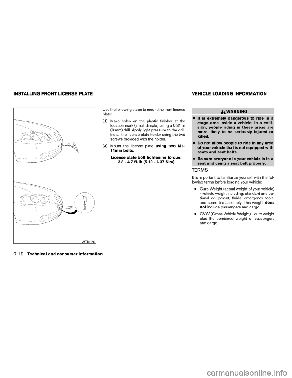
Use the following steps to mount the front license
plate:
s1Make holes on the plastic finisher at the
location mark (small dimple) using a 0.31 in
(8 mm) drill. Apply light pressure to the drill.
Install the license plate holder using the two
screws provided with the holder.
s2Mount the license plateusing two M6-
14mm bolts.
License plate bolt tightening torque:
3.8 - 4.7 ft-lb (5.10 - 6.37 N·m)
WARNING
cIt is extremely dangerous to ride in a
cargo area inside a vehicle. In a colli-
sion, people riding in these areas are
more likely to be seriously injured or
killed.
cDo not allow people to ride in any area
of your vehicle that is not equipped with
seats and seat belts.
cBe sure everyone in your vehicle is in a
seat and using a seat belt properly.
TERMS
It is important to familiarize yourself with the fol-
lowing terms before loading your vehicle:
cCurb Weight (actual weight of your vehicle)
- vehicle weight including: standard and op-
tional equipment, fluids, emergency tools,
and spare tire assembly. This weightdoes
notinclude passengers and cargo.
cGVW (Gross Vehicle Weight) - curb weight
plus the combined weight of passengers
and cargo.
WTI0076
INSTALLING FRONT LICENSE PLATE VEHICLE LOADING INFORMATION
9-12Technical and consumer information
ZREVIEW COPY:Ð2004 Sentra(b15)
Owners Manual(owners)ÐUSA English(nna)
03/18/04Ðtbrooks
X