2004 NISSAN PATROL lock
[x] Cancel search: lockPage 3 of 579
SECTION
AT
MODIFICATION NOTICE:
+Wiring diagrams have been changed.
+ Service data and Speci®cations (SDS) have been changed.
CONTENTS
RE4R03A
OVERALL SYSTEM ..................................................4002
Circuit Diagram ......................................................4002
Wiring Diagram Ð A/T Ð ......................................4003
RE5R05A
TROUBLE DIAGNOSIS ............................................. 4011
Circuit Diagram ...................................................... 4011
TROUBLE DIAGNOSES FOR SYMPTOMS .............4012
Wiring Diagram Ð AT Ð NONDTC.......................4012 SERVICE DATA AND SPECIFICATIONS (SDS)
......4014
General Speci®cations ...........................................4014
Vehicle Speed When Shifting Gears .....................4014
Vehicle Speed When Performing and Releasing
Lock-up ..................................................................4014
Stall Revolution ......................................................4014
Line Pressure.........................................................4014
Solenoid Valves .....................................................4015
A/T Fluid Temperature Sensor...............................4015
Turbine Revolution Sensor ....................................4015
Revolution Sensor .................................................4015
AT-4001
Page 16 of 579
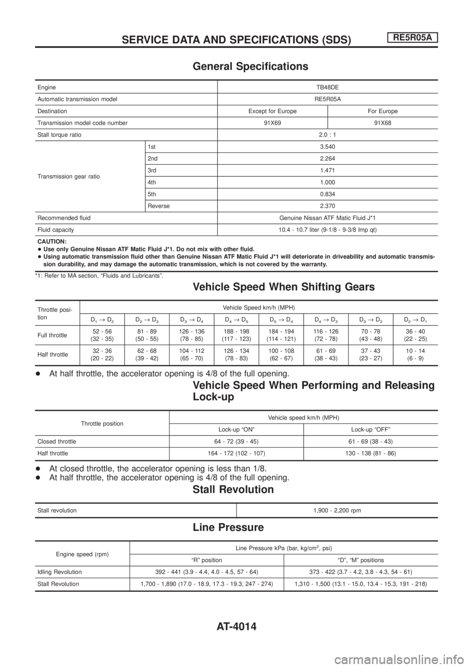
General Speci®cations
EngineTB48DE
Automatic transmission modelRE5R05A
Destination Except for Europe For Europe
Transmission model code number 91X69 91X68
Stall torque ratio2.0:1
Transmission gear ratio1st 3.540
2nd 2.264
3rd 1.471
4th 1.000
5th 0.834
Reverse 2.370
Recommended ¯uid Genuine Nissan ATF Matic Fluid J*1
Fluid capacity10.4 - 10.7 liter (9-1/8 - 9-3/8 Imp qt)
CAUTION:
+Use only Genuine Nissan ATF Matic Fluid J*1. Do not mix with other ¯uid.
+Using automatic transmission ¯uid other than Genuine Nissan ATF Matic Fluid J*1 will deteriorate in driveability and automatic transmis-
sion durability, and may damage the automatic transmission, which is not covered by the warranty.
*1: Refer to MA section, ªFluids and Lubricantsº.
Vehicle Speed When Shifting Gears
Throttle posi-
tionVehicle Speed km/h (MPH)
D
1®D2D2®D3D3®D4D4®D5D5®D4D4®D3D3®D2D2®D1
Full throttle52-56
(32 - 35)81-89
(50 - 55)126 - 136
(78 - 85)188 - 198
(117 - 123)184 - 194
(114 - 121)116 - 126
(72 - 78)70-78
(43 - 48)36-40
(22 - 25)
Half throttle32-36
(20 - 22)62-68
(39 - 42)104 - 112
(65 - 70)126 - 134
(78 - 83)100 - 108
(62 - 67)61-69
(38 - 43)37-43
(23 - 27)10-14
(6-9)
+At half throttle, the accelerator opening is 4/8 of the full opening.
Vehicle Speed When Performing and Releasing
Lock-up
Throttle positionVehicle speed km/h (MPH)
Lock-up ªONº Lock-up ªOFFº
Closed throttle 64 - 72 (39 - 45) 61 - 69 (38 - 43)
Half throttle 164 - 172 (102 - 107) 130 - 138 (81 - 86)
+At closed throttle, the accelerator opening is less than 1/8.
+At half throttle, the accelerator opening is 4/8 of the full opening.
Stall Revolution
Stall revolution1,900 - 2,200 rpm
Line Pressure
Engine speed (rpm)Line Pressure kPa (bar, kg/cm
2, psi)
ªRº position ªDº, ªMº positions
Idling Revolution 392 - 441 (3.9 - 4.4, 4.0 - 4.5, 57 - 64) 373 - 422 (3.7 - 4.2, 3.8 - 4.3, 54 - 61)
Stall Revolution 1,700 - 1,890 (17.0 - 18.9, 17.3 - 19.3, 247 - 274) 1,310 - 1,500 (13.1 - 15.0, 13.4 - 15.3, 191 - 218)
SERVICE DATA AND SPECIFICATIONS (SDS)RE5R05A
AT-4014
Page 22 of 579
Body Front End
+When removing or installing hood, place a cloth or other padding on front fender panel and cowl top. This
prevents vehicle body from being scratched.
+Bumper fascia is made of plastic. Do not use excessive force and be sure to keep oil away from it.
+Hood adjustment: Adjust at hinge portion.
+Hood lock adjustment: After adjusting, check hood lock control operation. Apply a coat of grease to hood
locks engaging mechanism.
+Hood opener: Do not attempt to bend cable forcibly. Doing so increases effort required to unlock hood.
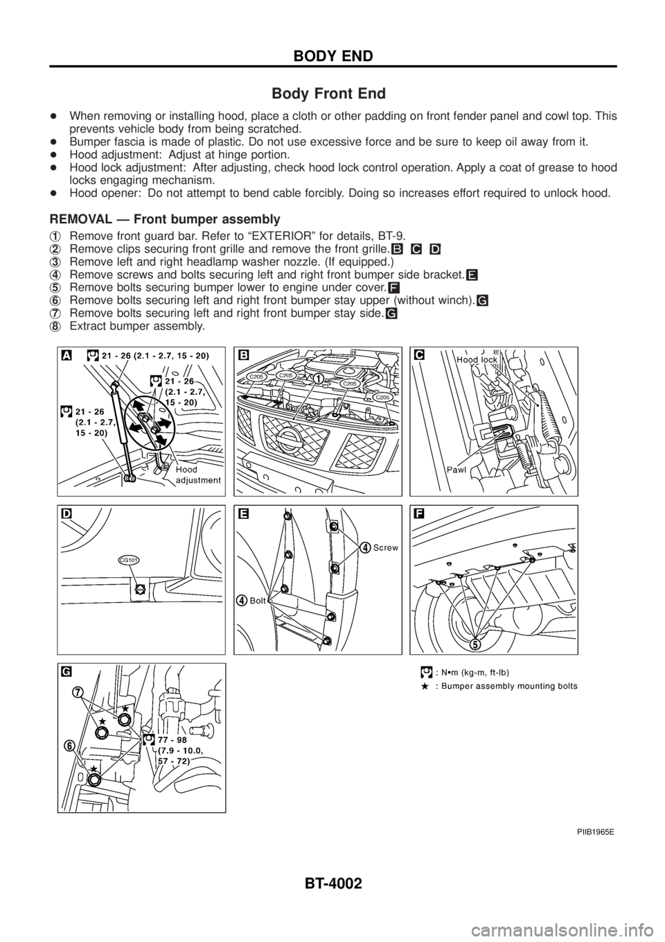
REMOVAL Ð Front bumper assembly
j1Remove front guard bar. Refer to ªEXTERIORº for details, BT-9.
j
2Remove clips securing front grille and remove the front grille.
j3Remove left and right headlamp washer nozzle. (If equipped.)
j
4Remove screws and bolts securing left and right front bumper side bracket.
j5Remove bolts securing bumper lower to engine under cover.
j6Remove bolts securing left and right front bumper stay upper (without winch).
j7Remove bolts securing left and right front bumper stay side.
j8Extract bumper assembly.
PIIB1965E
BODY END
BT-4002
Page 25 of 579
Body Rear End and Opener
+Bumper fascia is made of plastic. Do not use excessive force and be sure to keep oil away from it.
+Back door lock system adjustment: Adjust lock & striker so that they are in the center.
After adjustment, check back door lock operation.
+Back door hatch lock system adjustment: Adjust lock & striker so that they are in the center.
After adjustment, check back door hatch lock operation.
+Opener cable: Do not attempt to bend cable using excessive force.
+After installation, make sure that back door and fuel ®ller lid open smoothly.
WARNING:
+Be careful not to scratch back door stay and/or back door hatch stay when installing back door
and/or back door hatch. A scratched stay may cause gas leakage.
+The contents of the back door stay and back door hatch stay are under pressure. Do not take apart,
puncture, apply heat or allow ®re near them.
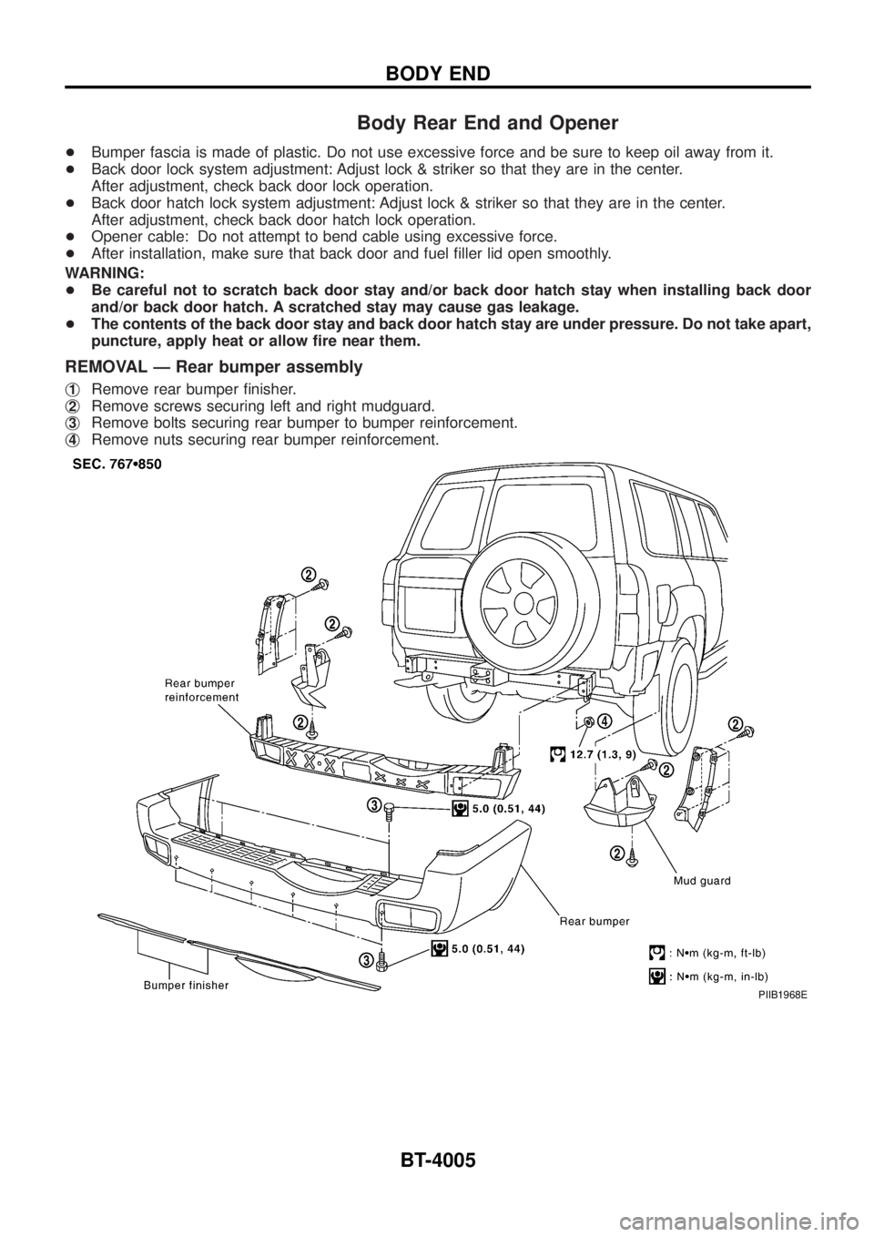
REMOVAL Ð Rear bumper assembly
j1Remove rear bumper ®nisher.
j
2Remove screws securing left and right mudguard.
j
3Remove bolts securing rear bumper to bumper reinforcement.
j
4Remove nuts securing rear bumper reinforcement.
PIIB1968E
BODY END
BT-4005
Page 34 of 579
Removal and Installation
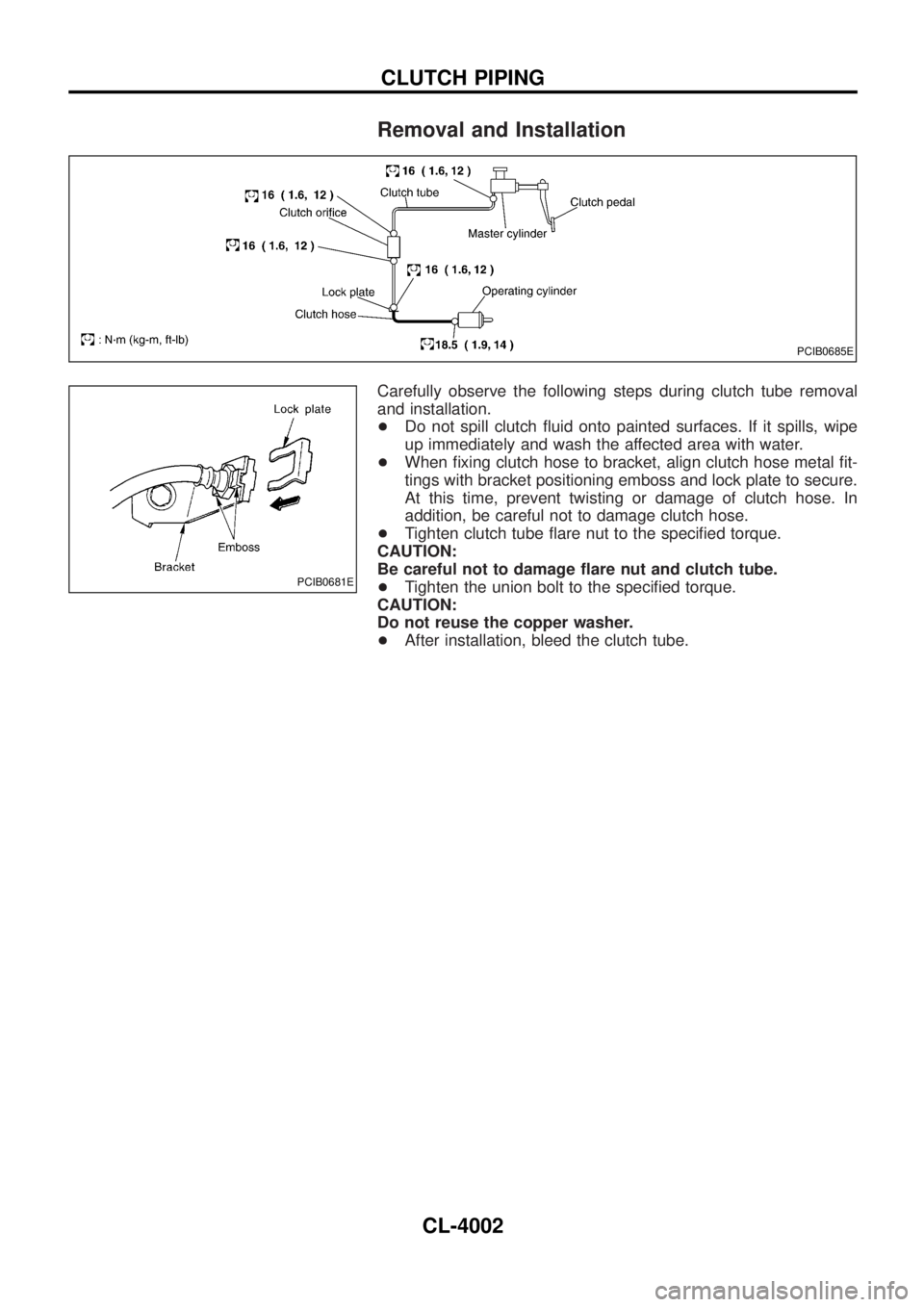
Carefully observe the following steps during clutch tube removal
and installation.
+Do not spill clutch ¯uid onto painted surfaces. If it spills, wipe
up immediately and wash the affected area with water.
+When ®xing clutch hose to bracket, align clutch hose metal ®t-
tings with bracket positioning emboss and lock plate to secure.
At this time, prevent twisting or damage of clutch hose. In
addition, be careful not to damage clutch hose.
+Tighten clutch tube ¯are nut to the speci®ed torque.
CAUTION:
Be careful not to damage ¯are nut and clutch tube.
+Tighten the union bolt to the speci®ed torque.
CAUTION:
Do not reuse the copper washer.
+After installation, bleed the clutch tube.
PCIB0685E
PCIB0681E
CLUTCH PIPING
CL-4002
Page 91 of 579
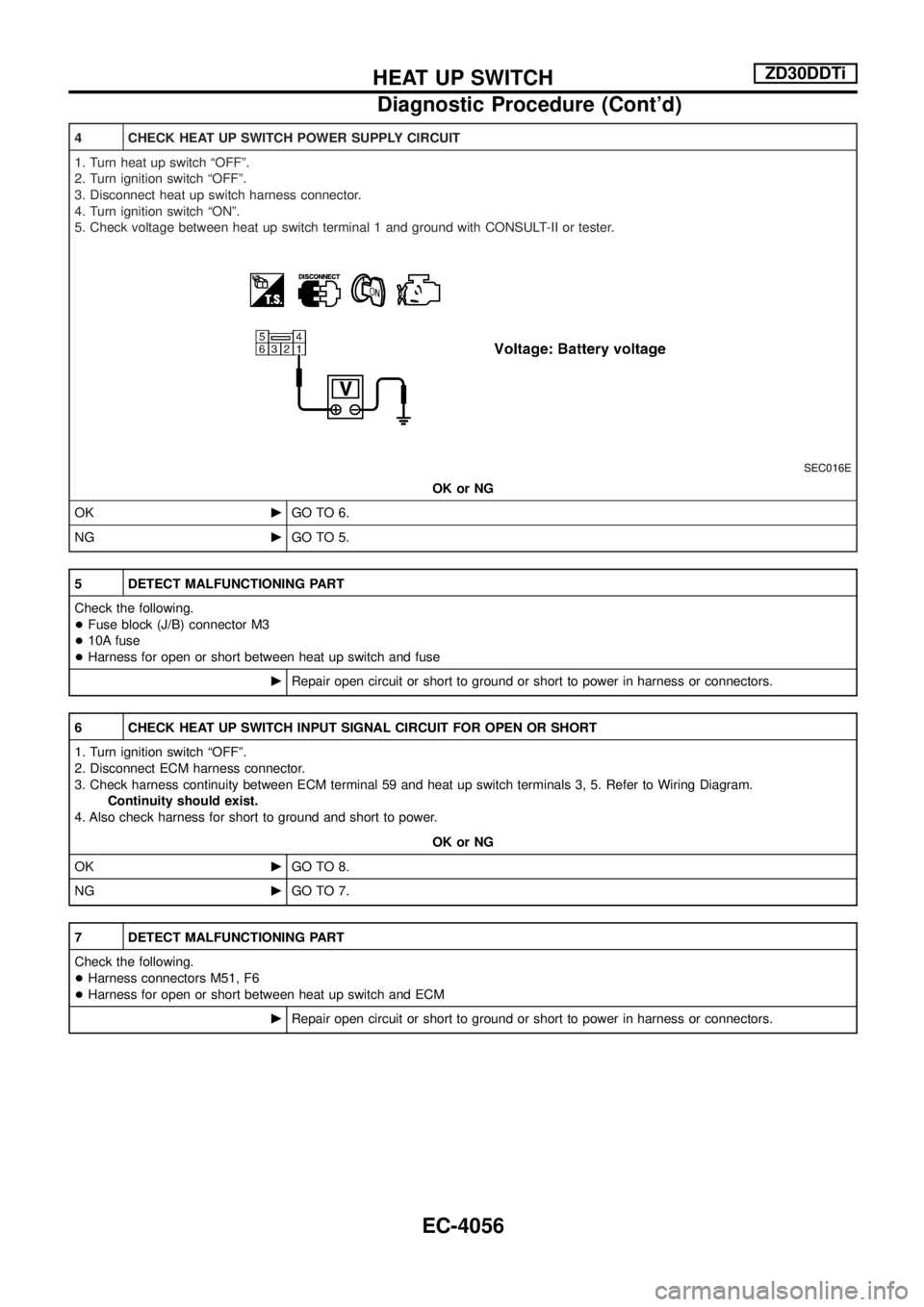
4 CHECK HEAT UP SWITCH POWER SUPPLY CIRCUIT
1. Turn heat up switch ªOFFº.
2. Turn ignition switch ªOFFº.
3. Disconnect heat up switch harness connector.
4. Turn ignition switch ªONº.
5. Check voltage between heat up switch terminal 1 and ground with CONSULT-II or tester.
SEC016E
OK or NG
OKcGO TO 6.
NGcGO TO 5.
5 DETECT MALFUNCTIONING PART
Check the following.
+Fuse block (J/B) connector M3
+10A fuse
+Harness for open or short between heat up switch and fuse
cRepair open circuit or short to ground or short to power in harness or connectors.
6 CHECK HEAT UP SWITCH INPUT SIGNAL CIRCUIT FOR OPEN OR SHORT
1. Turn ignition switch ªOFFº.
2. Disconnect ECM harness connector.
3. Check harness continuity between ECM terminal 59 and heat up switch terminals 3, 5. Refer to Wiring Diagram.
Continuity should exist.
4. Also check harness for short to ground and short to power.
OK or NG
OKcGO TO 8.
NGcGO TO 7.
7 DETECT MALFUNCTIONING PART
Check the following.
+Harness connectors M51, F6
+Harness for open or short between heat up switch and ECM
cRepair open circuit or short to ground or short to power in harness or connectors.
HEAT UP SWITCHZD30DDTi
Diagnostic Procedure (Cont'd)
EC-4056
Page 98 of 579
Terminals and Reference Value for NAVI Control
Unit........................................................................\
.4183
Terminals and Reference Value for Display ..........4185
Terminals and Reference Value for NAVI Switch ..4186
Terminals and Reference Value for Transfer Unit .4187
Terminals and Reference Value for Voice
Change Relay ........................................................4188
Self-Diagnosis Function .........................................4189
Self-Diagnosis Mode..............................................4189
Con®rmation/Adjustment Mode .............................4192
Trouble Diagnoses.................................................4198
Example of Symptoms Judged Not Malfunction ...4218
Program Loading ...................................................4226
DOOR MIRROR/WAGON AND HARDTOP
MODELS ....................................................................4227
Wiring Diagram Ð MIRROR Ð/LHD Models........4227
Wiring Diagram Ð MIRROR Ð/RHD Models .......4229
HEATED SEAT/WAGON AND HARDTOP
MODELS ....................................................................4231
Wiring Diagram Ð HSEAT Ð................................4231
AUTOMATIC SPEED CONTROL DEVICE (ASCD)/
WAGON AND HARDTOP MODELS .........................4233
Schematic/TB48 and TD42Ti Engine Models .......4233
Wiring Diagram Ð ASCD Ð/TB48 and TD42Ti
Engine Models .......................................................4234
POWER WINDOW/WAGON AND HARDTOP
MODELS ....................................................................4238
Schematic ..............................................................4238
Wiring Diagram Ð WINDOW Ð ...........................4239
POWER DOOR LOCK/WAGON AND HARDTOP
MODELS ....................................................................4244
Schematic/Without Theft Warning System
Models ...................................................................4244
Wiring Diagram Ð D/LOCK Ð/Without Theft
Warning System Models ........................................4245
Schematic/With Theft Warning System Models ....4249
Wiring Diagram Ð D/LOCK Ð/LHD Models With
Theft Warning System ...........................................4250
Wiring Diagram Ð D/LOCK Ð/RHD Models With
Theft Warning System ...........................................4254
POWER DOOR LOCK/WAGON AND HARDTOP
MODELS ....................................................................4258
Schematic Ð Super Lock Ð .................................4258
Wiring Diagram Ð S/LOCK Ð ..............................4259
MULTI-REMOTE CONTROL SYSTEM/WAGON
AND HARDTOP MODELS ........................................4264
Wiring Diagram Ð MULTI Ð/LHD Models Except
for Europe, The Middle East and With Theft
Warning System ....................................................4264
Wiring Diagram Ð MULTI Ð/RHD Models
Except for Europe, South Africa and With Theft
Warning System ....................................................4266 Schematic/With Theft Warning System Models ....4268
Wiring Diagram Ð MULTI Ð/LHD Models with
Theft Warning System ...........................................4269
Wiring Diagram Ð MULTI Ð/RHD Models with
Theft Warning System ...........................................4273
Wiring Diagram Ð MULTI Ð/LHD Models for
Europe and The Middle East.................................4276
THEFT WARNING SYSTEM/WAGON AND
HARDTOP MODELS .................................................4278
Schematic ..............................................................4278
Wiring Diagram Ð THEFT Ð/LHD Models ...........4279
Wiring Diagram Ð THEFT Ð/RHD Models ..........4284
SUPER LOCK CONTROL UNIT/WAGON AND
HARDTOP MODELS .................................................4290
Schematic/RHD Models for Europe ......................4290
UNIFIED METER CONTROL UNIT (TIME
CONTROL SYSTEM)/WAGON AND HARDTOP
MODELS ....................................................................4292
Schematic/Except RHD Models for Europe and
With Theft Warning System Models ......................4292
NATS (Nissan Anti-Theft System)/TB48DE
ENGINE MODELS FOR EUROPE ............................4293
Wiring Diagram Ð NATS Ð ..................................4293
NATS (Nissan Anti-Theft System)/ZD ENGINE
MODELS ....................................................................4295
Wiring Diagram Ð NATS Ð/LHD Models for
Europe ...................................................................4295
Wiring Diagram Ð NATS Ð/RHD Models for
Europe ...................................................................4297
LOCATION OF ELECTRICAL UNITS/WAGON
AND HARDTOP MODELS ........................................4300
Engine Compartment .............................................4300
Passenger Compartment Ð LHD Models .............4302
Passenger Compartment Ð RHD Models ............4304
HARNESS LAYOUT ..................................................4307
How to Read Harness Layout ...............................4307
HARNESS LAYOUT/WAGON AND HARDTOP
MODELS ....................................................................4308
Main Harness/LHD Models....................................4308
Main Harness/RHD Models ...................................4312
Engine Room Harness/LHD Models .....................4316
Engine Room Harness/RHD Models .....................4322
Engine Harness .....................................................4328
Body Harness/LHD Models ...................................4330
Body Harness/RHD Models...................................4334
Body No. 2 Harness/LHD Models .........................4338
Body No. 2 Harness/RHD Models.........................4340
Chassis Harness....................................................4342
Front Door Harness (Driver side) ..........................4343
Front Door Harness (Passenger side) ..................4344
Rear Door Harness................................................4345
CONTENTS(Cont'd)
EL-4003
Page 136 of 579
Bulb Replacement
CAUTION:
+After replacing a new xenon bulb, be sure to make aiming
adjustments.
+ Hold only the plastic base when handling the bulb. Never
touch the glass envelope.
+ Do not leave headlamp re¯ector without bulb for a long
period of time. Dust, moisture, smoke, etc. entering head-
lamp body may affect the performance of the headlamp.
Remove headlamp bulb from the headlamp re¯ector just
before a replacement bulb is installed.
1. Disconnect negative battery cable.
2. Remove side combination lamp and radiator grille.
3. Disconnect headlamp connector.
4. Remove headlamp assembly.
WARNING:
Never service a xenon headlamp with wet hands.
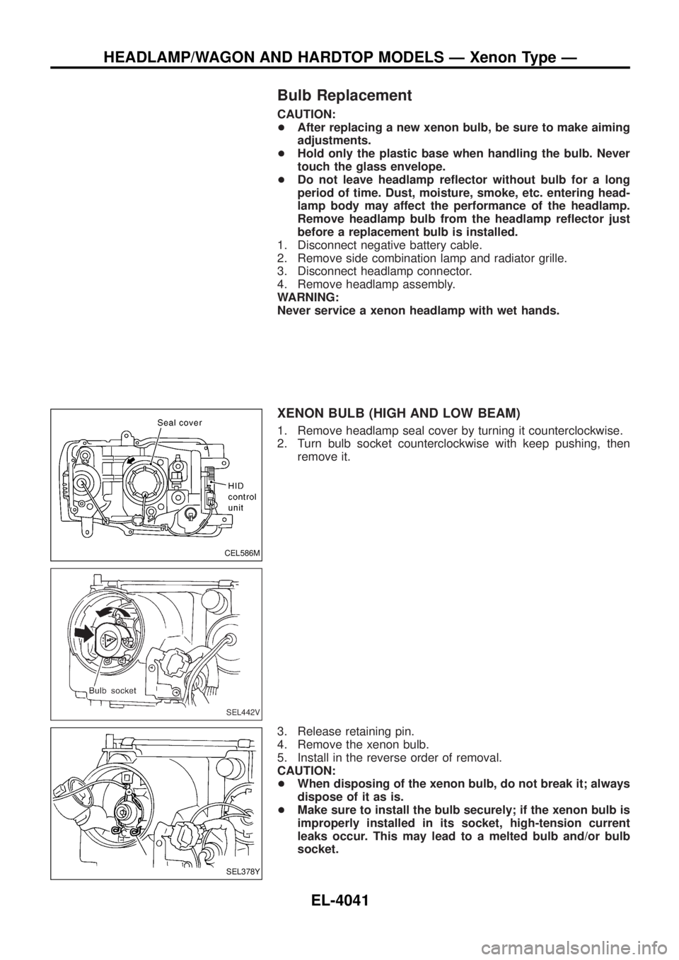
XENON BULB (HIGH AND LOW BEAM)
1. Remove headlamp seal cover by turning it counterclockwise.
2. Turn bulb socket counterclockwise with keep pushing, then remove it.
3. Release retaining pin.
4. Remove the xenon bulb.
5. Install in the reverse order of removal.
CAUTION:
+ When disposing of the xenon bulb, do not break it; always
dispose of it as is.
+ Make sure to install the bulb securely; if the xenon bulb is
improperly installed in its socket, high-tension current
leaks occur. This may lead to a melted bulb and/or bulb
socket.
CEL586M
SEL442V
SEL378Y
HEADLAMP/WAGON AND HARDTOP MODELS Ð Xenon Type Ð
EL-4041