Page 78 of 579
TER-
MINAL
NO.WIRE
COLORITEM CONDITIONDATA (DC Voltage and Pulse
Signal)
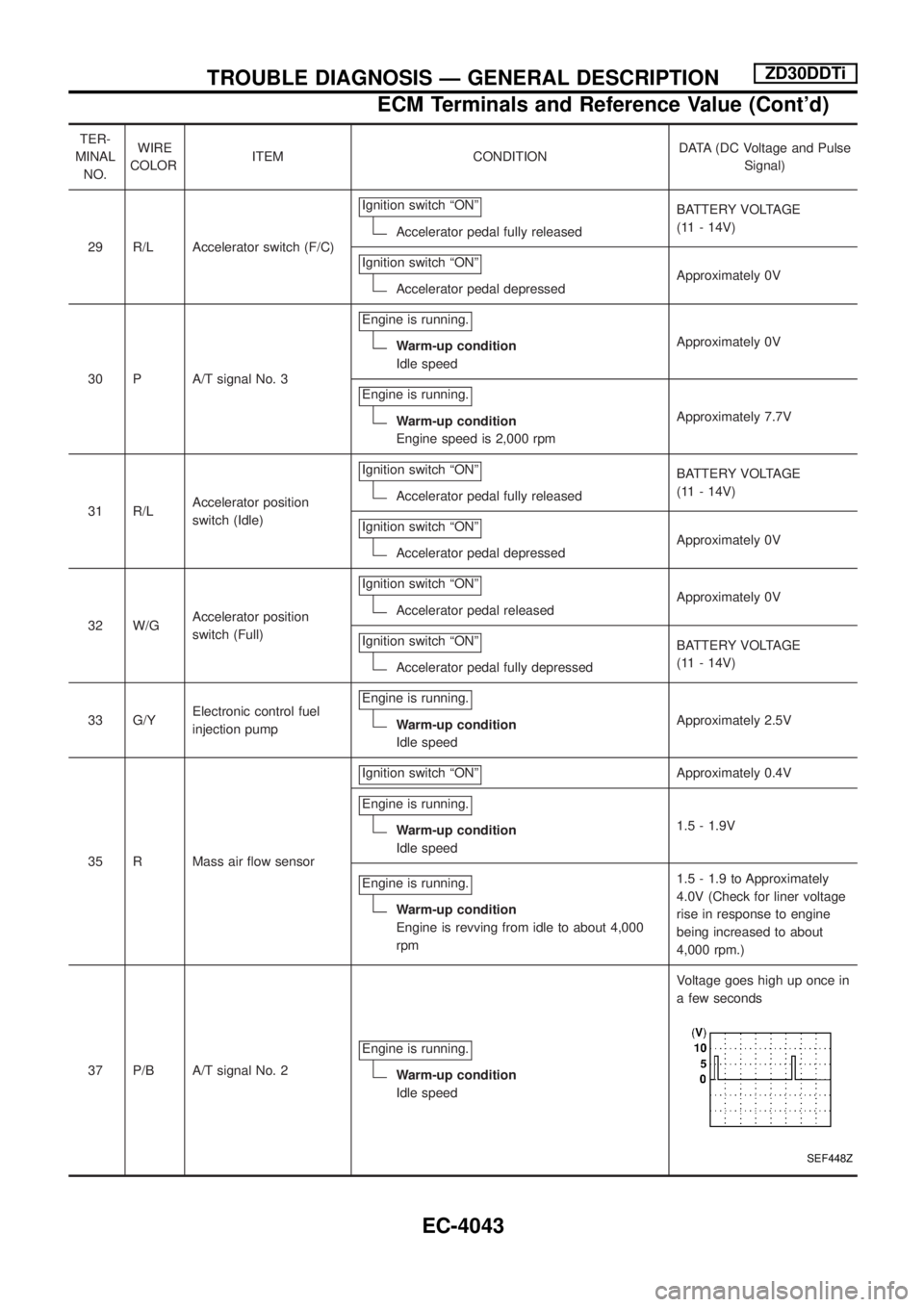
29 R/L Accelerator switch (F/C)Ignition switch ªONº
Accelerator pedal fully releasedBATTERY VOLTAGE
(11 - 14V)
Ignition switch ªONº
Accelerator pedal depressedApproximately 0V
30 P A/T signal No. 3Engine is running.
Warm-up condition
Idle speedApproximately 0V
Engine is running.
Warm-up condition
Engine speed is 2,000 rpmApproximately 7.7V
31 R/LAccelerator position
switch (Idle)Ignition switch ªONº
Accelerator pedal fully releasedBATTERY VOLTAGE
(11 - 14V)
Ignition switch ªONº
Accelerator pedal depressedApproximately 0V
32 W/GAccelerator position
switch (Full)Ignition switch ªONº
Accelerator pedal releasedApproximately 0V
Ignition switch ªONº
Accelerator pedal fully depressedBATTERY VOLTAGE
(11 - 14V)
33 G/YElectronic control fuel
injection pumpEngine is running.
Warm-up condition
Idle speedApproximately 2.5V
35 R Mass air ¯ow sensorIgnition switch ªONº
Approximately 0.4V
Engine is running.
Warm-up condition
Idle speed1.5 - 1.9V
Engine is running.
Warm-up condition
Engine is revving from idle to about 4,000
rpm1.5 - 1.9 to Approximately
4.0V (Check for liner voltage
rise in response to engine
being increased to about
4,000 rpm.)
37 P/B A/T signal No. 2Engine is running.
Warm-up condition
Idle speedVoltage goes high up once in
a few seconds
SEF448Z
TROUBLE DIAGNOSIS Ð GENERAL DESCRIPTIONZD30DDTi
ECM Terminals and Reference Value (Cont'd)
EC-4043
Page 79 of 579
TER-
MINAL
NO.WIRE
COLORITEM CONDITIONDATA (DC Voltage and Pulse
Signal)
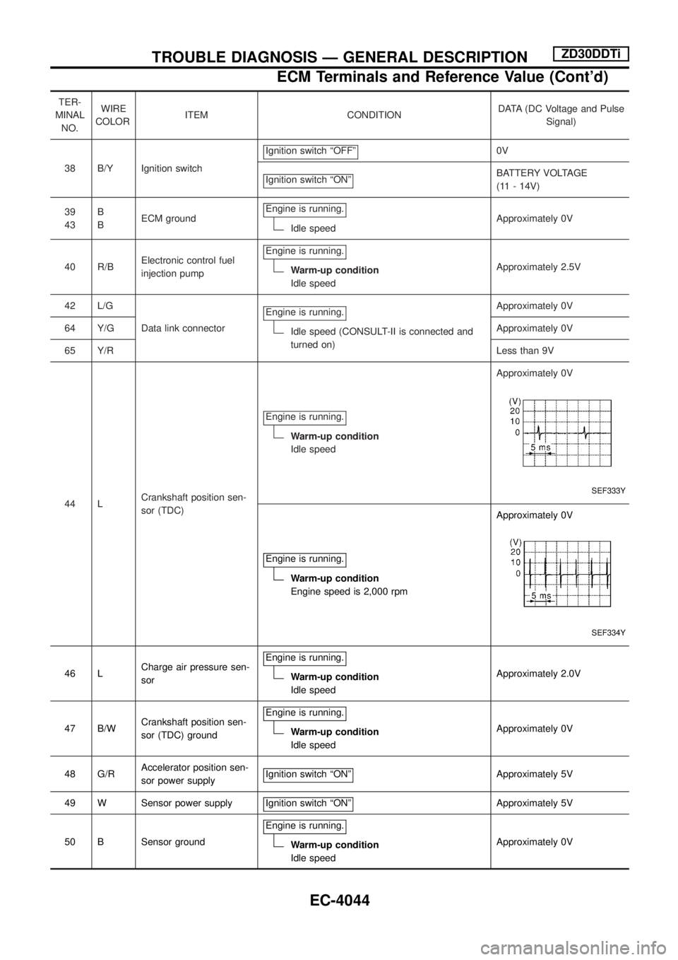
38 B/Y Ignition switchIgnition switch ªOFFº
0V
Ignition switch ªONº
BATTERY VOLTAGE
(11 - 14V)
39
43B
BECM groundEngine is running.
Idle speedApproximately 0V
40 R/BElectronic control fuel
injection pumpEngine is running.
Warm-up condition
Idle speedApproximately 2.5V
42 L/G
Data link connectorEngine is running.
Idle speed (CONSULT-II is connected and
turned on)Approximately 0V
64 Y/GApproximately 0V
65 Y/RLess than 9V
44 LCrankshaft position sen-
sor (TDC)Engine is running.
Warm-up condition
Idle speedApproximately 0V
SEF333Y
Engine is running.
Warm-up condition
Engine speed is 2,000 rpmApproximately 0V
SEF334Y
46 LCharge air pressure sen-
sorEngine is running.Warm-up condition
Idle speedApproximately 2.0V
47 B/WCrankshaft position sen-
sor (TDC) groundEngine is running.
Warm-up condition
Idle speedApproximately 0V
48 G/RAccelerator position sen-
sor power supplyIgnition switch ªONº
Approximately 5V
49 W Sensor power supply Ignition switch ªONº
Approximately 5V
50 B Sensor groundEngine is running.
Warm-up condition
Idle speedApproximately 0V
TROUBLE DIAGNOSIS Ð GENERAL DESCRIPTIONZD30DDTi
ECM Terminals and Reference Value (Cont'd)
EC-4044
Page 80 of 579
TER-
MINAL
NO.WIRE
COLORITEM CONDITIONDATA (DC Voltage and Pulse
Signal)
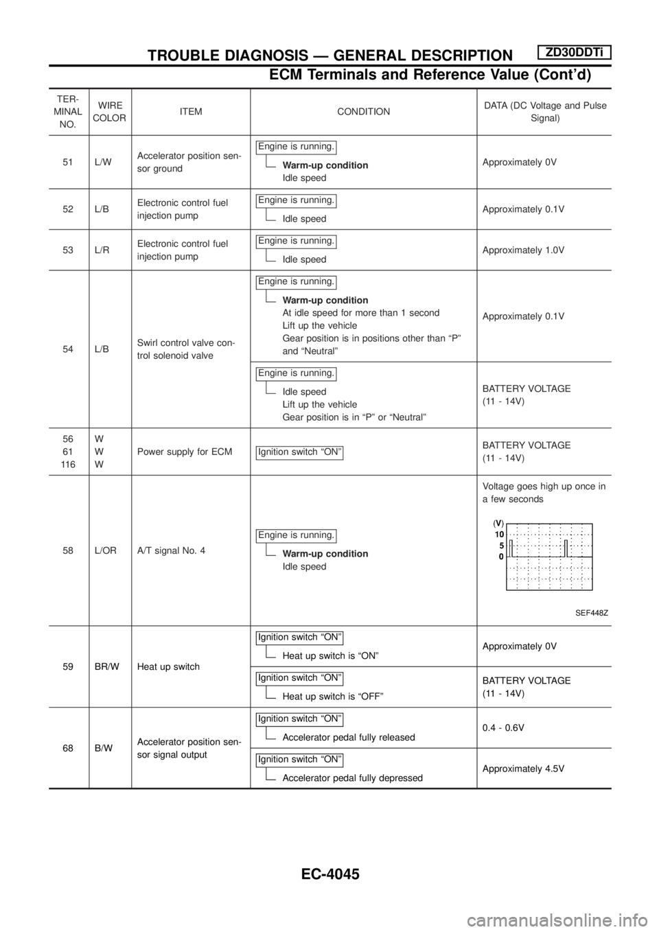
51 L/WAccelerator position sen-
sor groundEngine is running.
Warm-up condition
Idle speedApproximately 0V
52 L/BElectronic control fuel
injection pumpEngine is running.
Idle speedApproximately 0.1V
53 L/RElectronic control fuel
injection pumpEngine is running.
Idle speedApproximately 1.0V
54 L/BSwirl control valve con-
trol solenoid valveEngine is running.
Warm-up condition
At idle speed for more than 1 second
Lift up the vehicle
Gear position is in positions other than ªPº
and ªNeutralºApproximately 0.1V
Engine is running.
Idle speed
Lift up the vehicle
Gear position is in ªPº or ªNeutralºBATTERY VOLTAGE
(11 - 14V)
56
61
11 6W
W
WPower supply for ECM Ignition switch ªONº
BATTERY VOLTAGE
(11 - 14V)
58 L/OR A/T signal No. 4Engine is running.
Warm-up condition
Idle speedVoltage goes high up once in
a few seconds
SEF448Z
59 BR/W Heat up switchIgnition switch ªONºHeat up switch is ªONºApproximately 0V
Ignition switch ªONº
Heat up switch is ªOFFºBATTERY VOLTAGE
(11 - 14V)
68 B/WAccelerator position sen-
sor signal outputIgnition switch ªONº
Accelerator pedal fully released0.4 - 0.6V
Ignition switch ªONº
Accelerator pedal fully depressedApproximately 4.5V
TROUBLE DIAGNOSIS Ð GENERAL DESCRIPTIONZD30DDTi
ECM Terminals and Reference Value (Cont'd)
EC-4045
Page 81 of 579
TER-
MINAL
NO.WIRE
COLORITEM CONDITIONDATA (DC Voltage and Pulse
Signal)
101 R/BVariable nozzle turbo-
charger control solenoid
valveEngine is running.
Warm-up condition
Idle speedApproximately 6.8V
SEF253Z
Engine is running.
Warm-up condition
Engine speed is 2,000 rpmApproximately 11V
SEF254Z
102 G/R Current returnEngine is running.Idle speedBATTERY VOLTAGE
(11 - 14V)
103
105
109
11 5L/Y
L/W
L
R/LEGR volume control
valveEngine is running.
Warm-up condition
Idle speed0.1 - 14V
106
11 2
11 8B
B
BECM groundEngine is running.
Idle speedApproximately 0V
111 LG/B Glow relayRefer to ªGLOW CONTROL SYSTEMº, EC-252 in Service Manual (Publication No.
SM9E-Y61CG3).
TROUBLE DIAGNOSIS Ð GENERAL DESCRIPTIONZD30DDTi
ECM Terminals and Reference Value (Cont'd)
EC-4046
Page 82 of 579
Component Description
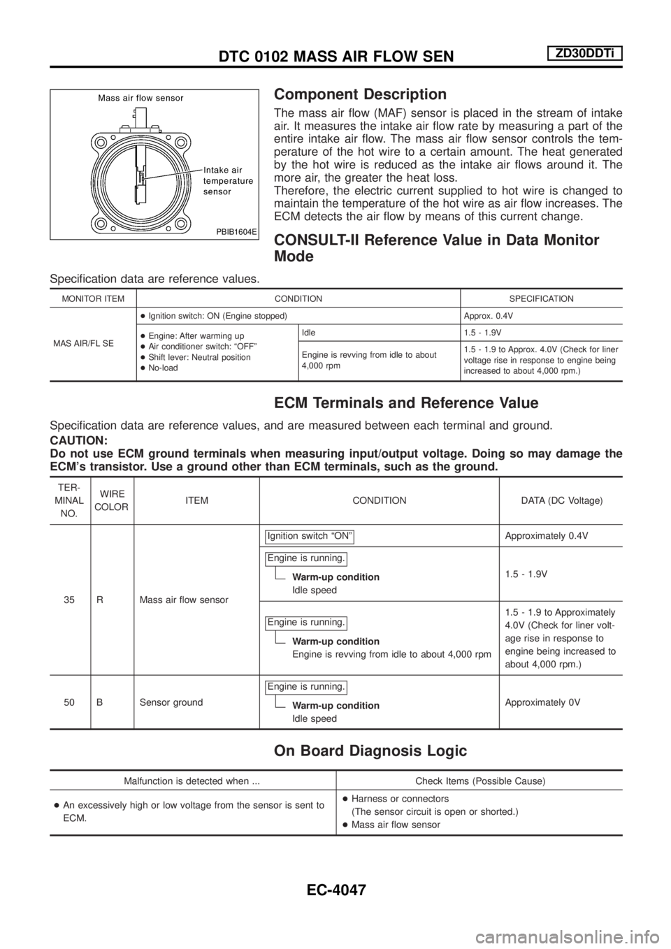
The mass air ¯ow (MAF) sensor is placed in the stream of intake
air. It measures the intake air ¯ow rate by measuring a part of the
entire intake air ¯ow. The mass air ¯ow sensor controls the tem-
perature of the hot wire to a certain amount. The heat generated
by the hot wire is reduced as the intake air ¯ows around it. The
more air, the greater the heat loss.
Therefore, the electric current supplied to hot wire is changed to
maintain the temperature of the hot wire as air ¯ow increases. The
ECM detects the air ¯ow by means of this current change.
CONSULT-II Reference Value in Data Monitor
Mode
Speci®cation data are reference values.
MONITOR ITEM CONDITION SPECIFICATION
MAS AIR/FL SE+Ignition switch: ON (Engine stopped) Approx. 0.4V
+Engine: After warming up
+Air conditioner switch: ªOFFº
+Shift lever: Neutral position
+No-loadIdle 1.5 - 1.9V
Engine is revving from idle to about
4,000 rpm1.5 - 1.9 to Approx. 4.0V (Check for liner
voltage rise in response to engine being
increased to about 4,000 rpm.)
ECM Terminals and Reference Value
Speci®cation data are reference values, and are measured between each terminal and ground.
CAUTION:
Do not use ECM ground terminals when measuring input/output voltage. Doing so may damage the
ECM's transistor. Use a ground other than ECM terminals, such as the ground.
TER-
MINAL
NO.WIRE
COLORITEM CONDITION DATA (DC Voltage)
35 R Mass air ¯ow sensorIgnition switch ªONº
Approximately 0.4V
Engine is running.
Warm-up condition
Idle speed1.5 - 1.9V
Engine is running.
Warm-up condition
Engine is revving from idle to about 4,000 rpm1.5 - 1.9 to Approximately
4.0V (Check for liner volt-
age rise in response to
engine being increased to
about 4,000 rpm.)
50 B Sensor groundEngine is running.
Warm-up condition
Idle speedApproximately 0V
On Board Diagnosis Logic
Malfunction is detected when ... Check Items (Possible Cause)
+An excessively high or low voltage from the sensor is sent to
ECM.+Harness or connectors
(The sensor circuit is open or shorted.)
+Mass air ¯ow sensor
PBIB1604E
DTC 0102 MASS AIR FLOW SENZD30DDTi
EC-4047
Page 83 of 579
DTC Con®rmation Procedure
WITH CONSULT-II
1) Turn ignition switch ªONº, and wait at least 6 seconds.
2) Select ªDATA MONITORº mode with CONSULT-II.
3) Start engine and wait at least 3 seconds.
4) If DTC is detected, go to ªDiagnostic Procedureº, EC-4050.
WITHOUT CONSULT-II
1) Turn ignition switch ªONº, and wait at least 6 seconds.
2) Start engine and wait at least 3 seconds.
3) Turn ignition switch ªOFFº, wait at least 5 seconds and then turn
ªONº.
4) Perform ªDiagnostic Test Mode II (Self-diagnostic results)º with
ECM.
5) If DTC is detected, go to ªDiagnostic Procedureº, EC-4050.
SEF817Y
DTC 0102 MASS AIR FLOW SENZD30DDTi
EC-4048
Page 86 of 579

3 CHECK MAF SENSOR GROUND CIRCUIT FOR OPEN AND SHORT
1. Turn ignition switch ªOFFº.
2. Loosen and retighten engine ground screws.
SEF227Z
3. Disconnect ECM harness connector.
4. Disconnect TCM harness connector.
5. Check harness continuity between mass air ¯ow sensor terminal 3 and ECM terminal 50, TCM terminal 42. Refer to Wiring Dia-
gram.
Continuity should exist.
6. Also check harness for short to ground and short to power.
OK or NG
OKcGO TO 5.
NGcGO TO 4.
4 DETECT MALFUNCTIONING PART
Check the following.
+Harness connectors E230, F12
+Harness connectors M51, F6
+Harness connectors E106, M88
+Harness for open or short between mass air ¯ow sensor and ECM
+Harness for open or short between mass air ¯ow sensor and TCM (Transmission control module)
cRepair open circuit or short to ground or short to power in harness or connectors.
5 CHECK MAF SENSOR INPUT SIGNAL CIRCUIT FOR OPEN AND SHORT
1. Check harness continuity between mass air ¯ow sensor terminal 4 and ECM terminal 35. Refer to Wiring Diagram.
Continuity should exist.
2. Also check harness for short to ground and short to power.
OK or NG
OKcGO TO 7.
NGcGO TO 6.
6 DETECT MALFUNCTIONING PART
Check the following.
+Harness connectors E230, F12
+Harness for open or short between mass air ¯ow sensor and ECM
cRepair open circuit or short to ground or short to power in harness or connectors.
DTC 0102 MASS AIR FLOW SENZD30DDTi
Diagnostic Procedure (Cont'd)
EC-4051
Page 87 of 579
7 CHECK SHIELD CIRCUIT
1. Disconnect harness connectors E230, F12.
2. Check harness continuity between harness connector F12 terminal 5 and ground.
Refer to Wiring Diagram.
Continuity should exist.
3. Also check harness for short to power.
OK or NG
OKcGO TO 9.
NGcGO TO 8.
8 DETECT MALFUNCTIONING PART
Check the following.
+Joint connector-4
+Harness for open or short between harness connector F12 and ground
cRepair open circuit or short to power in harness or connectors.
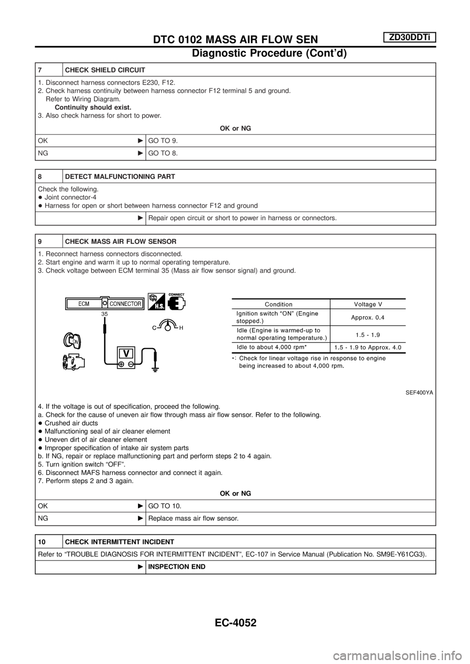
9 CHECK MASS AIR FLOW SENSOR
1. Reconnect harness connectors disconnected.
2. Start engine and warm it up to normal operating temperature.
3. Check voltage between ECM terminal 35 (Mass air ¯ow sensor signal) and ground.
SEF400YA
4. If the voltage is out of speci®cation, proceed the following.
a. Check for the cause of uneven air ¯ow through mass air ¯ow sensor. Refer to the following.
+Crushed air ducts
+Malfunctioning seal of air cleaner element
+Uneven dirt of air cleaner element
+Improper speci®cation of intake air system parts
b. If NG, repair or replace malfunctioning part and perform steps 2 to 4 again.
5. Turn ignition switch ªOFFº.
6. Disconnect MAFS harness connector and connect it again.
7. Perform steps 2 and 3 again.
OK or NG
OKcGO TO 10.
NGcReplace mass air ¯ow sensor.
10 CHECK INTERMITTENT INCIDENT
Refer to ªTROUBLE DIAGNOSIS FOR INTERMITTENT INCIDENTº, EC-107 in Service Manual (Publication No. SM9E-Y61CG3).
cINSPECTION END
DTC 0102 MASS AIR FLOW SENZD30DDTi
Diagnostic Procedure (Cont'd)
EC-4052