Page 210 of 262

CHECKING PARKING BRAKEFrom the released position, pull the parking
brake lever up slowly and firmly. If the number of
clicks is out of the range listed above, see your
NISSAN dealer.
CHECKING BRAKE PEDALWith the engine running, check the distance
between the upper surface of the pedal and the
metal floor. If it is out of the range shown above,
see your NISSAN dealer.Self-adjusting brakesYour vehicle is equipped with self-adjusting
brakes.
The disc-type brakes self-adjust every time the
brake pedal is applied.
WARNING
See your NISSAN dealer and have it
checked if the brake pedal height does
not return to normal.Brake pad wear indicatorsThe disc brake pads on your vehicle have au-
dible wear indicators. When a brake pad re-
quires replacement, it will make a high pitched
scraping or screeching sound when the vehicle
is in motion whether or not the brake pedal is
depressed. Have the brakes checked as soon as
possible if the wear indicator sound is heard.
Under some driving or climate conditions, occa-
sional brake squeak, squeal or other noise may
be heard. Occasional brake noise during light to
moderate stops is normal and does not affect
the function or performance of the brake system.
Proper brake inspection intervals should
be followed.For additional information, see the
appropriate maintenance log shown in the Ser-
vice and Maintenance Guide.
SDI1447
DI1020ML
PARKING BRAKE AND BRAKE
PEDAL
Maintenance and do-it-yourself
8-21
�
04.5.17/Z33-D/V5.0
�
Page 211 of 262
 remains the
same from")
BRAKE BOOSTERCheck the brake booster function as follows:
1. With the engine off, press and release the
brake pedal several times. When brake pedal
movement (distance of travel) remains the
same from one pedal application to the next,
continue on to the next step.
2. While depressing the brake pedal, start the
engine. The pedal height should drop a little.
3. With the brake pedal depressed, stop the
engine. Keeping the pedal depressed for
about 30 seconds, the pedal height should
not change.
4. Run the engine for one minute without de-
pressing the brake pedal, then turn it off.
Depress the brake pedal several times. The
pedal travel distance will decrease gradually
with each depression as the vacuum is re-
leased from the booster.
If the brakes do not operate properly, see your
NISSAN dealer.
CAUTION
Never use a fuse of higher or lower
amperage rating than that specified on
the fuse box cover. This could damage
the electrical system or cause a fire.
ENGINE COMPARTMENTIf any electrical equipment does not operate,
check for an open fuse.
1. Be sure the ignition key and headlight switch
are OFF.
2. Open the engine hood and remove the cover
on the battery and the fuse/fusible link holder.
3. Remove the fuse/fusible link holder cover.
4. Remove the fuse with the fuse puller.
5. If the fuse is open, replace it with a new fuse.
6. If a new fuse also opens, have the electrical
SDI1479
FUSES
8-22
Maintenance and do-it-yourself
�
04.5.17/Z33-D/V5.0
�
Page 212 of 262
system checked and repaired by your
NISSAN dealer.
Fusible linksIf any electrical equipment does not operate and
fuses are in good condition, check the fusible
links. If any of these fusible links are melted,
replace only with genuine NISSAN parts.
PASSENGER COMPARTMENTIf any electrical equipment does not operate,
check for an open fuse.
1. Be sure the ignition key and the headlight
switch are OFF.
2. Open the fuse box lid.
3. Pinch the fuse perpendicularly with the fuse
puller and pull it out.
4. If the fuse is open, replace it with a new fuse.
5. If a new fuse also opens, have the electrical
system checked and repaired by your
NISSAN dealer.
SDI1393
Maintenance and do-it-yourself
8-23
�
04.5.17/Z33-D/V5.0
�
Page 214 of 262
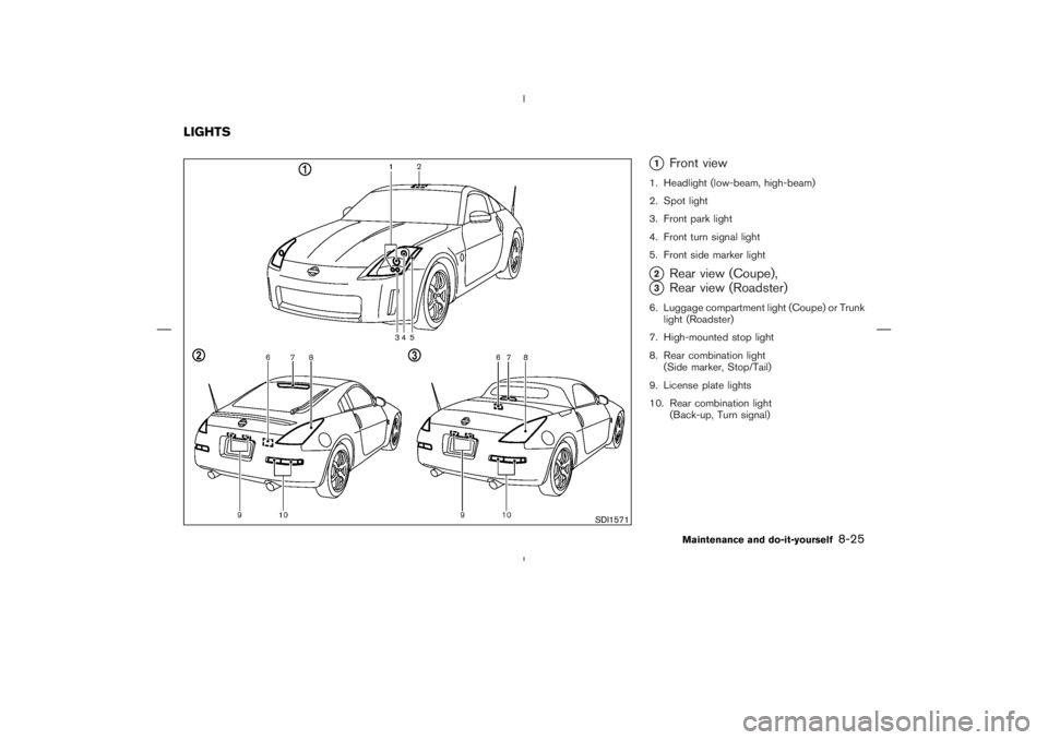
�1
Front view
1. Headlight (low-beam, high-beam)
2. Spot light
3. Front park light
4. Front turn signal light
5. Front side marker light�2
Rear view (Coupe),
�3
Rear view (Roadster)
6. Luggage compartment light (Coupe) or Trunk
light (Roadster)
7. High-mounted stop light
8. Rear combination light
(Side marker, Stop/Tail)
9. License plate lights
10. Rear combination light
(Back-up, Turn signal)
SDI1571
LIGHTS
Maintenance and do-it-yourself
8-25
�
04.5.17/Z33-D/V5.0
�
Page 215 of 262

HEADLIGHTS
ReplacingIf replacement is required, see a NISSAN dealer.
Xenon headlight bulb:
WARNINGHIGH VOLTAGE
When xenon headlights are on, they
produce a high voltage. To prevent an
electric shock, never attempt to modify
or disassemble the headlight assembly.
Always have your xenon headlights re-
placed at a NISSAN dealer. For addi-
tional information, see “Headlight and
turn signal switch” in the “2. Instru-
ments and controls” section.
Halogen headlight bulb:
The headlight is a semi-sealed beam type which
uses a replaceable headlight (halogen) bulb. A
bulb can be replaced from under the engine
compartment without removing the headlight
assembly.
CAUTION
�High pressure halogen gas is sealed
inside the halogen bulb. The bulb
may break if the glass envelope is
scratched or the bulb is dropped.
�When handling the bulb, do not touch
the glass envelope.
�Do not touch the bulb.
�Use the same number and wattage as
originally installed:
Bulb no. (Wattage)
D2R (35W) - Xenon low-beam
H7 (55W) - High-beam
or
H7 (55W) - Halogen low-beam
H1 (55W) - High-beam
�Do not leave the bulb out of the
headlight reflector for a long period
of time as dust, moisture, and smoke
may enter the headlight body and
affect the performance of the head-
light.
8-26
Maintenance and do-it-yourself
�
04.5.17/Z33-D/V5.0
�
Page 216 of 262
EXTERIOR AND INTERIOR LIGHTS
Item Wattage (W) BulbNo.
Front turn signal light* 21 T20
Front park light* 5 T10
Front side marker light* 5 T10
Rear combination light (Upper)
Stop/Tail 21/5 T20
Side marker 5 T10
Rear combination light (Lower)
Back-up* 21 T20
Turn signal* 21 T20
License plate light (x 2) 5 T10
High-mounted stop light* (LED) —
Spot light 8 —
Luggage compartment light (Coupe) 5 —
Trunk light (Roadster)* 3.4 —
Vanity mirror light (if so equipped) 1.32 —
Rear floor box light* 1.4 —
*: See a NISSAN dealer for replacement.
Replacement proceduresAll other lights are either type A, B, C or D. When
replacing a bulb, first remove the lens and/or
cover.
MDI0006
Maintenance and do-it-yourself
8-27
�
04.5.17/Z33-D/V5.0
�
Page 217 of 262
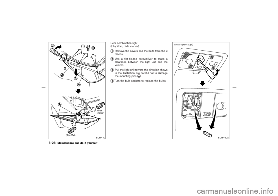
Rear combination light
(Stop/Tail, Side marker)�1Remove the covers and the bolts from the 3
places.
�2Use a flat-bladed screwdriver to make a
clearance between the light unit and the
vehicle.
�3Pull the light unit toward the direction shown
in the illustration. Be careful not to damage
the mounting pins
�A.
�4Turn the bulb sockets to replace the bulbs.
SDI1449
SDI1450A
8-28
Maintenance and do-it-yourself
�
04.5.17/Z33-D/V5.0
�
Page 218 of 262
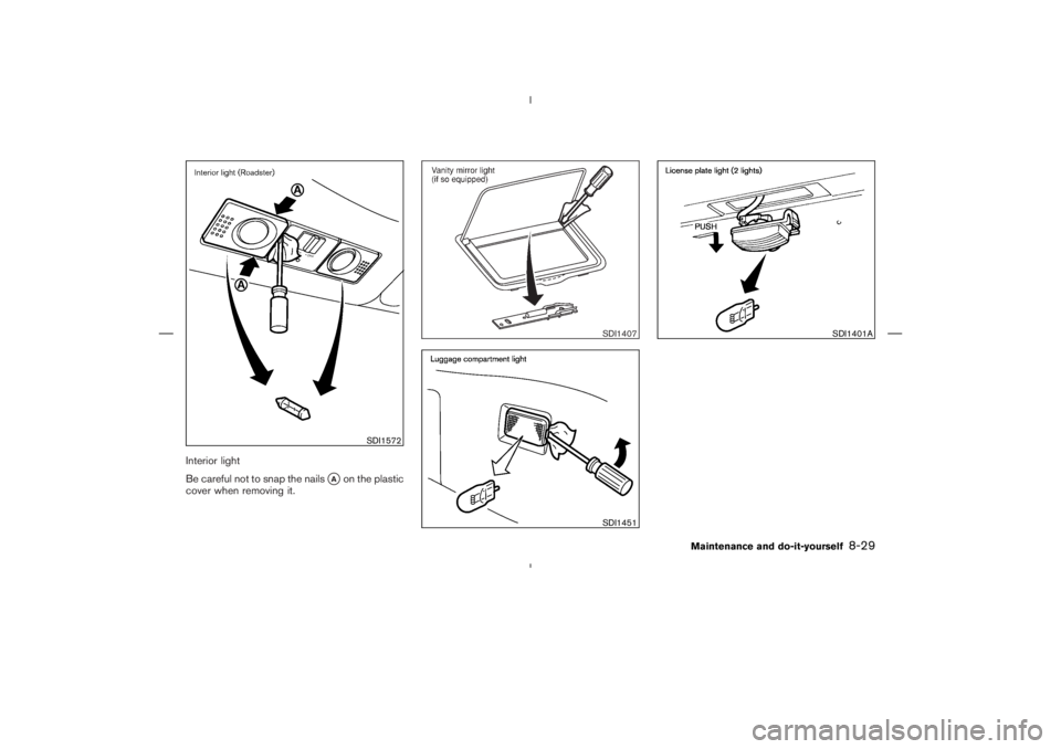
Interior light
Be careful not to snap the nails
�Aon the plastic
cover when removing it.
SDI1572
SDI1407SDI1451
SDI1401A
Maintenance and do-it-yourself
8-29
�
04.5.17/Z33-D/V5.0
�

 BulbNo.
Front turn signal light* 21 T20
Front park light* 5 T10
Front side marker light* 5 T10
Rear combination light (Upper)
Stop/Tail 21/5 T20
Side mark")