Page 247 of 314

247 Practical hints
Flat tire
�
Remove the wheel.
�
Take the spare tire out of the trunk.
Mounting the new wheel
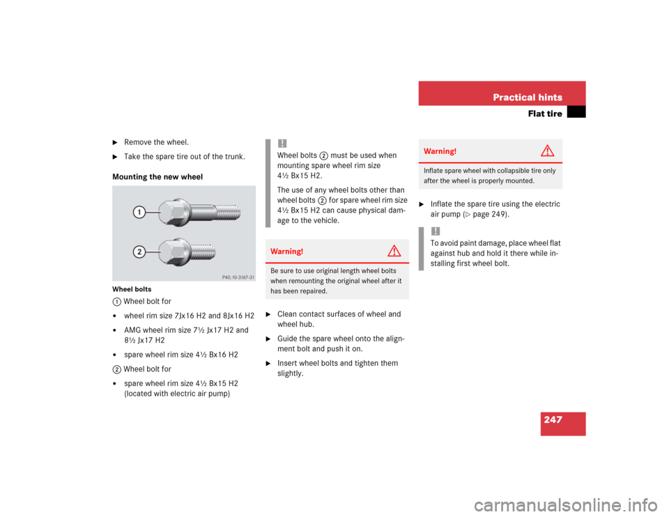
Wheel bolts1 Wheel bolt for�
wheel rim size 7Jx16 H2 and 8Jx16 H2
�
AMG wheel rim size 7½ Jx17 H2 and
8½ Jx17 H2
�
spare wheel rim size 4½ Bx16 H2
2 Wheel bolt for
�
spare wheel rim size 4½ Bx15 H2
(located with electric air pump)
�
Clean contact surfaces of wheel and
wheel hub.
�
Guide the spare wheel onto the align-
ment bolt and push it on.
�
Insert wheel bolts and tighten them
slightly.
�
Inflate the spare tire using the electric
air pump (
�page 249).
!Wheel bolts2must be used when
mounting spare wheel rim size
4½ Bx15 H2.
The use of any wheel bolts other than
wheel bolts2for spare wheel rim size
4½ Bx15 H2 can cause physical dam-
age to the vehicle.Warning!
G
Be sure to use original length wheel bolts
when remounting the original wheel after it
has been repaired.
Warning!
G
Inflate spare wheel with collapsible tire only
after the wheel is properly mounted.!To avoid paint damage, place wheel flat
against hub and hold it there while in-
stalling first wheel bolt.
Page 249 of 314

249 Practical hints
Flat tire
�
Before storing the jack in the trunk, it
should be fully collapsed, with pin and
handle folded in.
Inflating the collapsible spare tire
�
Take the electric air pump out of the
trunk (
�page 214).
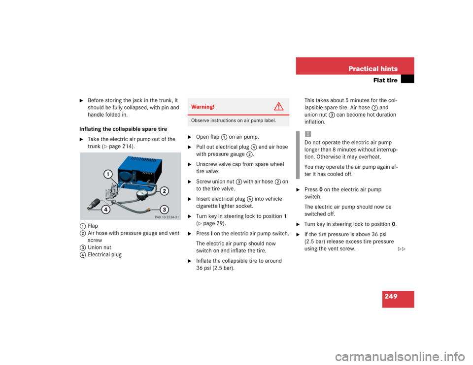
1Flap
2Air hose with pressure gauge and vent
screw
3Union nut
4Electrical plug
�
Open flap1 on air pump.
�
Pull out electrical plug4 and air hose
with pressure gauge2.
�
Unscrew valve cap from spare wheel
tire valve.
�
Screw union nut3 with air hose2 on
to the tire valve.
�
Insert electrical plug4 into vehicle
cigarette lighter socket.
�
Turn key in steering lock to position1
(�page 29).
�
PressI on the electric air pump switch.
The electric air pump should now
switch on and inflate the tire.
�
Inflate the collapsible tire to around
36 psi (2.5 bar).This takes about 5 minutes for the col-
lapsible spare tire. Air hose2 and
union nut3 can become hot duration
inflation.
�
Press0 on the electric air pump
switch.
The electric air pump should now be
switched off.
�
Turn key in steering lock to position0.
�
If the tire pressure is above 36 psi
(2.5 bar) release excess tire pressure
using the vent screw.
Warning!
G
Observe instructions on air pump label.
!Do not operate the electric air pump
longer than 8 minutes without interrup-
tion. Otherwise it may overheat.
You may operate the air pump again af-
ter it has cooled off.
��
Page 250 of 314

250 Practical hintsFlat tire
�
Detach the electric air pump.
�
Reinstall tire valve cap.
�
Stow the electrical plug and the air
hose behind the flap and place the air
pump back in the trunk.
�
Close the trunk lid.Storing collapsible spare wheel in
wheel well
Before you can store the spare wheel with
collapsible tire in the wheel well you have
to release the air pressure of the tire.
�
Unscrew valve stem removal tool,
which is part of the valve cap, from tire
valve.
�
Using the valve stem removal tool,
open tire valve slightly by turning the
tire valve insert counterclockwise to
release air pressure.
�
When the air pressure has been re-
leased, remove tire valve insert (pro-
tect it from dirt and sand) using the
previously removed tire valve cap.
�
Once all air is out of the tire, and the
tire has collapsed to its original shape,
reinstall the tire valve insert and valve
cap.
�
Place spare wheel in wheel well and
secure it with the pump holder.
�
Turn pump holder clockwise to its stop.
Warning!
G
Follow recommended inflation pressures.
Do not overinflate tires. Overinflating tires
can result in sudden deflation (blowout) be-
cause they are more likely to become punc-
tured or damaged by road debris, potholes
etc.
Do not underinflate tires. Underinflated tires
wear unevenly, adversely affect handling
and fuel economy, and are more likely to fail
from being overheated.
Do not overload the tires by exceeding the
specified vehicle capacity weight (as indicat-
ed by the label on the pillar in the driver’s
door opening). Overloading the tires can
overheat them, possibly causing a blowout.
Warning!
G
To prevent possible injury when unscrewing
air pump filler hose from tire valve after in-
flating the tire, use a rag since the tire valve
could be hot.
��
Page 259 of 314
259 Practical hints
Towing the vehicle
Installing towing eye bolt
SLK 32 AMG, Sport Package*
The rear towing eye is located at the right,
below the bumper.
SLK 32 AMG and Sport Package are fitted
with a towing eye bolt.
The towing eye bolt is stored with the jack
in the trunk (
�page 213).The threaded hole for the towing eye bolt
is located on the passenger-side behind
the grille in the bumper panel.
1Grille SLK 32 AMG, Sport Package*Removing grille
�
Hold grille1 (arrow) and pull forward.
Installing towing eye bolt
�
Take towing eye bolt and wheel wrench
out of trunk.
�
Screw towing eye bolt into its stop and
tighten with wheel wrench.
Removing towing eye bolt
�
Loosen towing eye bolt with wheel
wrench.
�
Unscrew towing eye bolt.
�
Store towing eye bolt and wheel
wrench in trunk.
Installing grille
�
Position grille1 and press securely
The grille should audibly snap into
place.
Page 260 of 314
260 Practical hintsFuses
�FusesA special fuse extractor is supplied with
the vehicle tool kit in the trunk.
Spare fuses are supplied inside the corre-
sponding fuse box.
The fuse chart is printed on the cover of
the corresponding fuse box.
The amperages of the fuses are also given
there.
Main fuse box
The main fuse box is located in the engine
compartment on the left hand side.
The main fuse box contains fuses for
interior consumers.
1Main fuse boxOpening
�
Release clamp (arrow) and lift fuse box
cover1.
�
Remove fuse box cover.
Closing
�
Fit fuse box cover1 back into the rear
clamp.
�
Close fuse box cover until the clamp
engages.
iOnly install fuses that have been tested
and approved by Mercedes-Benz and
that have the specified amperage rat-
ing.
Never attempt to repair or bridge a
blown fuse. Have the cause determined
and remedied by an authorized
Mercedes-Benz Center.
Page 276 of 314
276 Technical dataWeights
�WeightsTrunk load max.
110lb (50kg)
Page 290 of 314

290 Technical termsRetractable hardtop
Hardtop that can be opened and closed
at the push of a button and stored in
the trunk.
Roll bar
Occupant protection system which
consists of tubular steel sheathed in
plastic.
RON
(R
esearch O
ctane N
umber)
The Research Octane Number for gaso-
line as determined by a standardized
method. It is an indication of a gaso-
line's ability to resist undesired detona-
tion (knocking). The average of both
the ->MON (Motor Octane Number)
and RON (Research Octane Number) is
posted at the pump, also known as
ANTI-KNOCK INDEX.Shift lock
When the vehicle is parked, this lock
prevents the transmission selector le-
ver from being moved out of positionP
without key turned and brake pedal de-
pressed.
SRS
(S
upplemental R
estraint S
ystem)
Seat belts, emergency tensioning de-
vice and airbags. Though independent
systems, they are closely interfaced to
provide effective occupant protection.
Tele Aid System
(T
elematic A
larm I
dentification on
D
emand)
The Tele Aid system consists of three
types of response: automatic and man-
ual emergency, roadside assistance
and information. Tele Aid is initially ac-
tivated by completing a subscriber
agreement and placing an acquain-
tance call.The Tele Aid system is operational pro-
vided that the vehicle’s battery is
charged, properly connected, not dam-
aged and cellular and GPS coverage is
available.
Tightening torque
Force times lever arm (e.g. a lug
wrench) with which threaded fasteners
such as wheel bolts are tightened.
TIREFIT
Accessory for emergency and tempo-
rary tire repair. The TIREFIT kit consists
of a container with sealant material, a
filler hose, a valve stem tool, a valve in-
sert, and an air compressor.
Page 296 of 314

296 IndexCentral locking
From inside 80
Unlocking from inside 80
Certification label 266
Changing CDs
CD mode 121
Charging
Vehicle battery 252
CHECK ENGINE malfunction indicator
lamp 205
Checking
Coolant level 173, 180
Oil level 172, 175
Tire inflation pressure 173
Vehicle lighting 173
Child safety 60
Airbags 54
Infant and child restraint systems 57,
60
Cigarette lighter 143
Cleaning
Cloth upholstery 197Cup holder 196
Gear selector lever 196
Hard plastic trim items 196
Headliner 197
Instrument cluster 196
Leather upholstery 197
Light alloy wheels 196
Plastic and rubber parts 197
Rear window 195
Seat belts 197
Steering wheel 196
Windows 195
Windshield 45
Wiper blades 195
Cleaning*
Headlamps 99
Climate control 102
Adjusting air distribution 105
Adjusting air volume 105
Air conditioning 106
Air recirculation mode 106
Deactivating the climate control
system 110
Defogging windshield 110
Defrosting 109Reactivating the climate control
system 110
Rear window defroster 101
Residual heat utilization 107
Residual ventilation 107
Setting the temperature 104
Clock 21
Setting 91
Closing
Glove box 139
Hood 175
Retractable hardtop 221
Side windows 128
Trunk lid 78
Windows 128
Closing hardtop
In an emergency 221
Cloth upholstery
Cleaning 197
Cockpit 18, 287
Coin holder 142
Collapsible tire 287