Page 337 of 434
336 Practical hintsReplacing bulbs�
Gently push bulb into socket, turn
counterclockwise and remove.
�
Insert new bulb and reinstall bulb sock-
et.
The bulb socket should audibly click
into place.
�
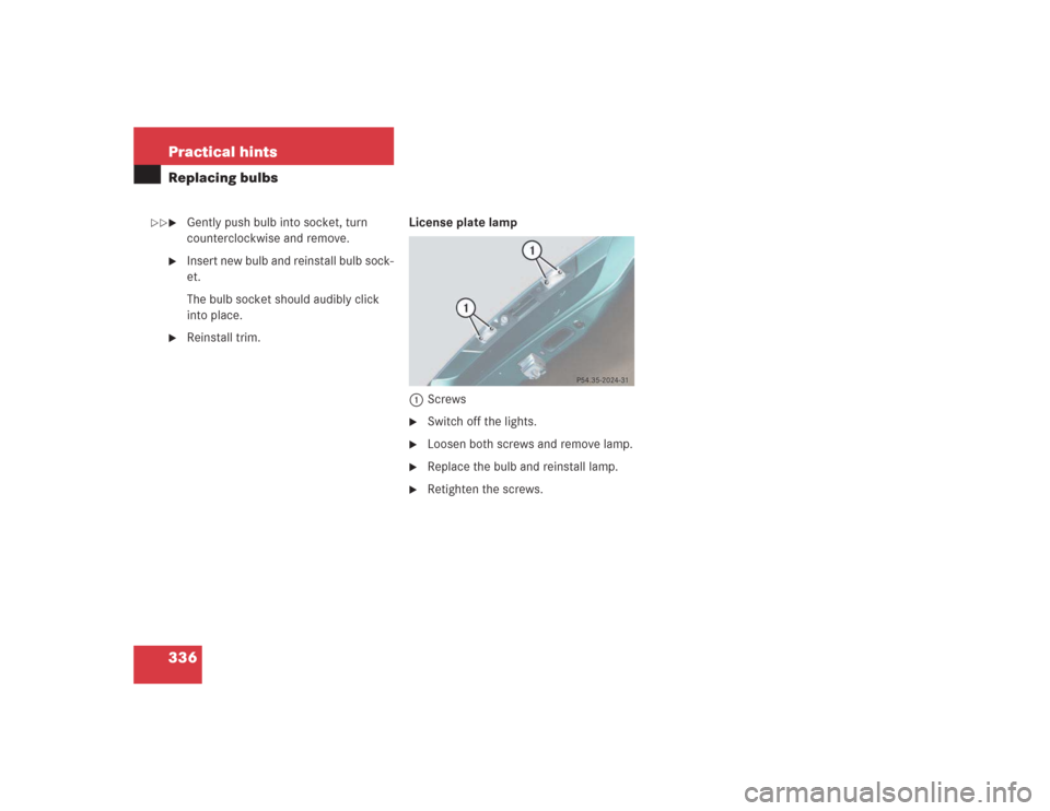
Reinstall trim.License plate lamp
1Screws
�
Switch off the lights.
�
Loosen both screws and remove lamp.
�
Replace the bulb and reinstall lamp.
�
Retighten the screws.
��
Page 344 of 434

343 Practical hints
Flat tire
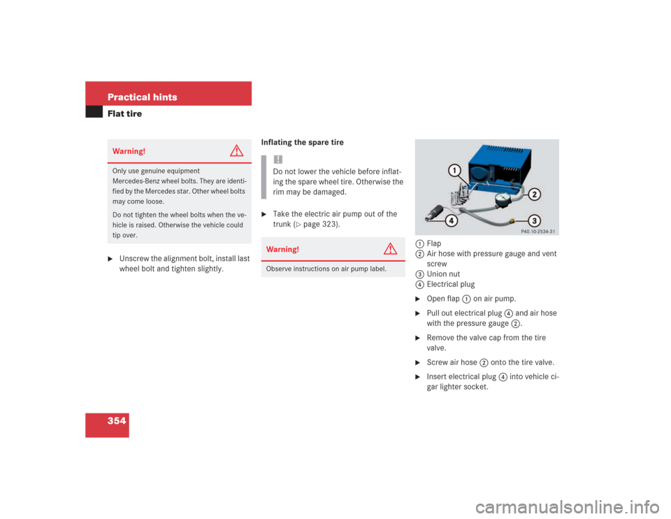
1Flap
2Air hose with pressure gauge and vent
screw
3Union nut
4Electrical plug�
Open flap 1 on air pump.
�
Pull out electrical plug 4 and air hose
with the pressure gauge 2.
�
Screw air hose 2 onto the tire valve.
�
Insert electrical plug 4 into vehicle ci-
gar lighter socket.
�
Turn the SmartKey in the ignition to po-
sition 1 (
�page 31).
or
�
Press the KEYLESS-GO* start/stop
button on the gear selector lever once.
Do not depress brake pedal.
�
Press I on the electric air pump switch.
The electric air pump should now
switch on and inflate the tire.
After 5 minutes, the pressure gauge must
display at least 26 psi (1.8 bar). The air
hose and the union nut can become hot
during inflation. Please exercise appropri-
ate caution.
�
If this tire pressure is not attained, turn
off the electric air pump, detach the air
hose from the tire valve, and again
drive vehicle back and forth very slowly
approximately 30 ft (10 m).
This serves to better distribute the
TIREFIT sealant material inside the tire.
�
Inflate the tire again.
�
Press 0 on the electric air pump switch.
�
Turn the SmartKey in the ignition to
position0.
or
�
Press KEYLESS-GO* start/stop button
on the gear selector lever twice. Do not
depress brake pedal.
The electric air pump should now be
switched off.!Do not operate the electric air pump
longer than eight minutes without in-
terruption. Otherwise it may overheat.
You may operate the air pump again af-
ter it has cooled off.
��
Page 348 of 434

347 Practical hints
Flat tire
�
Screw the air pump’s air hose5 onto
flange6 of the TIREFIT container.
�
Stick TIREFIT container1 upside
down into notch3 of the electric air
pump.
7Tire valve
8Electric air pump switch
9Air hose with pressure gauge and vent
screw
aFiller hose
�
Unscrew the valve cap from tire
valve7.
�
Screw filler hosea onto tire valve7.
�
Insert electrical plug4 into vehicle
cigarette lighter socket.
�
Turn the SmartKey in the starter switch
to position1 (
�page 31).
or
�
Press the KEYLESS-GO* start/stop
button (
�page 33) on the gear selec-
tor lever once. Do not depress brake
pedal.
�
Press I on electric air pump switch8.
The electric air pump should now
switch on and inflate the tire.After 5 minutes, the pressure gauge must
display at least 26 psi (1.8 bar). The air
hose can become hot during inflation.
Please exercise appropriate caution.
�
If this tire pressure is not attained, turn
off the electric air pump, detach the fill-
er hose from the tire valve, and drive
vehicle back and forth very slowly ap-
proximately 30 ft (10 m).
This serves to better distribute the
TIREFIT sealant material inside the tire.
�
Unscrew the air pump’s air hose5
from flange6 of the TIREFIT contain-
er.
�
Screw air hose5onto tire valve7.
�
Inflate the tire again.
Warning!
G
Observe safety instructions on air pump la-
bel.
!Do not operate the electric air pump
longer than eight minutes without in-
terruption. Otherwise it may overheat.
You may operate the air pump again af-
ter it has cooled off.
��
Page 354 of 434

353 Practical hints
Flat tire
Removing the wheel
1Alignment bolt�
Unscrew upper-most wheel bolt and re-
move.
�
Replace this wheel bolt with alignment
bolt1 supplied in the tool kit.
�
Remove the remaining bolts.
�
Remove the wheel.Mounting the new wheel
�
Clean contact surfaces of wheel and
wheel hub.
�
Guide the spare wheel onto the align-
ment bolt and push it on.
�
Insert wheel bolts and tighten them
slightly.
!Do not place wheel bolts in sand or dirt.
This could result in damage to the bolt
and wheel hub threads.
Warning!
G
Inflate spare wheel tire only after the wheel
is properly mounted.
Inflate the spare wheel tire using the electric
pump (
�page 354)
before
lowering the ve-
hicle.
Warning!
G
Always replace wheel bolts that are dam-
aged or rusted.
Never apply oil or grease to wheel bolts.
Damaged wheel hub threads should be re-
paired immediately. Do not continue to drive
under these circumstances! Contact an au-
thorized Mercedes-Benz Center or call
Roadside Assistance.
Incorrect wheel bolts or improperly tight-
ened wheel bolts can cause the wheel to
come off. This could cause an accident. Be
sure to use the correct wheel bolts.
Page 355 of 434
354 Practical hintsFlat tire�
Unscrew the alignment bolt, install last
wheel bolt and tighten slightly.Inflating the spare tire
�
Take the electric air pump out of the
trunk (
�page 323).
1Flap
2Air hose with pressure gauge and vent
screw
3Union nut
4Electrical plug
�
Open flap 1 on air pump.
�
Pull out electrical plug 4 and air hose
with the pressure gauge 2.
�
Remove the valve cap from the tire
valve.
�
Screw air hose 2 onto the tire valve.
�
Insert electrical plug 4 into vehicle ci-
gar lighter socket.
Warning!
G
Only use genuine equipment
Mercedes-Benz wheel bolts. They are identi-
fied by the Mercedes star. Other wheel bolts
may come loose.
Do not tighten the wheel bolts when the ve-
hicle is raised. Otherwise the vehicle could
tip over.
!Do not lower the vehicle before inflat-
ing the spare wheel tire. Otherwise the
rim may be damaged.Warning!
G
Observe instructions on air pump label.
Page 365 of 434

364 Practical hintsJump startingThe starter battery is located on the right
side of the engine compartment.�
Make sure the two vehicles do not
touch.
�
Turn off all electrical consumers.
�
Apply parking brake.
�
Shift gear selector lever to positionP.
�
Remove the red cover from positive ter-
minal on both vehicles (
�page 358).1Negative terminal of charged battery
2Negative terminal of discharged
battery
3Positive terminal of discharged battery
4Positive terminal of charged battery
�
Connect positive terminals 3 and 4
of the batteries with the jumper cables.
Clamp cable to charged battery 4
first.
�
Start the engine of the vehicle with the
charged battery and run at idle speed.
�
Connect negative terminals 1 and 2
of the batteries with the jumper cables.
Clamp cable to charged battery 1
first.
�
Start the engine of the disabled vehi-
cle.
You can now turn on the electrical con-
sumers. Do not turn on the lights under
any circumstances.
�
Remove the jumper cables first from
negative terminals 1 and 2 and then
from positive terminals 3 and 4.
You can now turn on the lights.
�
Have the battery checked at the near-
est Mercedes-Benz Center.
Warning!
G
Keep flames or sparks away from battery.
Do not smoke.
Observe all safety instructions and precau-
tions when handling automotive batteries
(�page 260).
!Never invert the terminal connections.
!Do not tow-start the vehicle.
Page 380 of 434
379 Technical data
Rims and tires
Same size tires
17’’ tires
18’’ tires
SL 500*
SL 600
SL 55 AMG
Rims (light alloy)
81/2 J x 17
-
-
Wheel offset
1.38 in (35 mm)
-
-
Summer tires (radial-ply tires)
255/45 R17 98W
-
-
Winter tires (radial-ply tires)
255/45 R17 98V M+S
-
-
SL 500
SL 600
SL 55 AMG
Rims (light alloy)
81/2 J x 18
81/2 J x 18
81/2 J x 18
Wheel offset
1.38 in (35 mm)
1.38 in (35 mm)
1.18 in (30 mm)
Summer tires (radial-ply tires)
-
-
-
Winter tires (radial-ply tires)
255/40 R18 95V M+S
255/40 R18 95V M+S
255/40 R18 95V M+S
Page 381 of 434
380 Technical dataRims and tiresMixed size tires
SL 500
SL 500 (Sport Package*)
SL 600
SL 600 (Sport Package*)
Front axle:Rims (light alloy)
81/2 J x 18
81/2 J x 18
Wheel offset
1.38 in (35 mm)
1.38 in (35 mm)
Summer tires (radial-ply tires)
255/40 R18 95W
255/40 R18 95Y
Rear axle:Rims (light alloy)
91/2 J x 18
91/2 J x 18
Wheel offset
1.57 in (40 mm)
1.57 in (40 mm)
Summer tires (radial-ply tires)
285/35 R18 97W
1
1Must not be used with snow chains.
285/35 R18 97Y
1

81/2 J x 17
-
-
Wheel offset
1.38 in (35 mm)
-
-
Summer tires (radial-pl")

SL 600
SL 600 (Sport Package*)
Front axle:Rims (light alloy)
81/2 J x 18
81/2 J x 18
Wheel offset
1.38 in (35 mm)
1.38 i")