Page 334 of 434

333 Practical hints
Replacing bulbs
Notes on bulb replacement�
Only use 12 volt bulbs of the same type
and with the specified watt rating.
�
Switch lights off before changing a bulb
to prevent short circuits.
�
Always use a clean lint-free cloth when
handling bulbs.
�
Your hands should be dry and free of oil
and grease.
�
If the newly installed bulb does not
come on, visit an authorized
Mercedes-Benz Center.Have the LEDs and bulbs for the following
lamps replaced by an authorized
Mercedes-Benz Center:
�
the additional turn signals in the exteri-
or rear view mirrors
�
the high mounted brake lamp
�
the brake lamps
�
the parking lamps and the side marker
lamps in the tail lamp assemblies
�
the rear fog lamps
�
the low beam (Xenon or Bi-Xenon*)
lamps
�
the front fog lamps
Warning!
G
Bulbs and bulb sockets can be very hot. Al-
low the lamp to cool down before changing
a bulb.
Keep bulbs out of reach of children.
Halogen lamps contain pressurized gas. A
bulb can explode if you:�
touch or move it when hot,
�
drop the bulb,
�
scratch the bulb.
Wear eye and hand protection.
Because of high voltage in Xenon lamps, it is
dangerous to replace the bulb or repair the
lamp and its components. We recommend
that you have such work done by a qualified
technician.
Page 335 of 434
. Do not remove.
3High beam lamp coverReplacing fron")
334 Practical hintsReplacing bulbsReplacing bulbs for front lamps
1Bulb socket for turn signal lamp
2Low beam lamp cover (Xenon or
Bi-Xenon* lamp). Do not remove.
3High beam lamp coverReplacing front turn signal bulb
�
Switch off the lights.
�
Open the hood (
�page 253).
�
Twist bulb socket 1 counterclockwise
and pull out.
�
Push bulb into socket, turn counter-
clockwise and remove.
�
Insert new bulb in socket, push and
twist clockwise.
�
Reinsert bulb socket in lamp and twist
clockwise.Replacing high beam bulbs
1High beam bulbs
2Locking mechanism
3Parking and standing lamps
�
Switch off the lights.
�
Open the hood (
�page 253).
�
Press ends of headlamp cover tab to-
gether and remove cover.
�
Pull electrical connector off.
�
Turn locking mechanism 2 counter-
clockwise and take out the bulb.
�
Insert the new bulb so that the base lo-
cates in the recess on the holder.
Warning!
G
Do not remove the cover for the Xenon or
Bi-Xenon* headlamp. Because of high volt-
age in Xenon and Bi-Xenon* lamps, it is dan-
gerous to replace the bulb or repair the lamp
and its components. We recommend that
you have such work done by a qualified
technician.
Page 348 of 434

347 Practical hints
Flat tire
�
Screw the air pump’s air hose5 onto
flange6 of the TIREFIT container.
�
Stick TIREFIT container1 upside
down into notch3 of the electric air
pump.
7Tire valve
8Electric air pump switch
9Air hose with pressure gauge and vent
screw
aFiller hose
�
Unscrew the valve cap from tire
valve7.
�
Screw filler hosea onto tire valve7.
�
Insert electrical plug4 into vehicle
cigarette lighter socket.
�
Turn the SmartKey in the starter switch
to position1 (
�page 31).
or
�
Press the KEYLESS-GO* start/stop
button (
�page 33) on the gear selec-
tor lever once. Do not depress brake
pedal.
�
Press I on electric air pump switch8.
The electric air pump should now
switch on and inflate the tire.After 5 minutes, the pressure gauge must
display at least 26 psi (1.8 bar). The air
hose can become hot during inflation.
Please exercise appropriate caution.
�
If this tire pressure is not attained, turn
off the electric air pump, detach the fill-
er hose from the tire valve, and drive
vehicle back and forth very slowly ap-
proximately 30 ft (10 m).
This serves to better distribute the
TIREFIT sealant material inside the tire.
�
Unscrew the air pump’s air hose5
from flange6 of the TIREFIT contain-
er.
�
Screw air hose5onto tire valve7.
�
Inflate the tire again.
Warning!
G
Observe safety instructions on air pump la-
bel.
!Do not operate the electric air pump
longer than eight minutes without in-
terruption. Otherwise it may overheat.
You may operate the air pump again af-
ter it has cooled off.
��
Page 354 of 434

353 Practical hints
Flat tire
Removing the wheel
1Alignment bolt�
Unscrew upper-most wheel bolt and re-
move.
�
Replace this wheel bolt with alignment
bolt1 supplied in the tool kit.
�
Remove the remaining bolts.
�
Remove the wheel.Mounting the new wheel
�
Clean contact surfaces of wheel and
wheel hub.
�
Guide the spare wheel onto the align-
ment bolt and push it on.
�
Insert wheel bolts and tighten them
slightly.
!Do not place wheel bolts in sand or dirt.
This could result in damage to the bolt
and wheel hub threads.
Warning!
G
Inflate spare wheel tire only after the wheel
is properly mounted.
Inflate the spare wheel tire using the electric
pump (
�page 354)
before
lowering the ve-
hicle.
Warning!
G
Always replace wheel bolts that are dam-
aged or rusted.
Never apply oil or grease to wheel bolts.
Damaged wheel hub threads should be re-
paired immediately. Do not continue to drive
under these circumstances! Contact an au-
thorized Mercedes-Benz Center or call
Roadside Assistance.
Incorrect wheel bolts or improperly tight-
ened wheel bolts can cause the wheel to
come off. This could cause an accident. Be
sure to use the correct wheel bolts.
Page 355 of 434
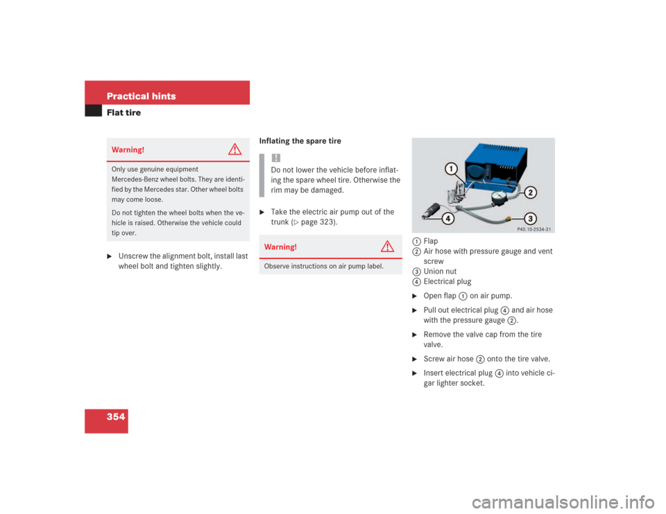
354 Practical hintsFlat tire�
Unscrew the alignment bolt, install last
wheel bolt and tighten slightly.Inflating the spare tire
�
Take the electric air pump out of the
trunk (
�page 323).
1Flap
2Air hose with pressure gauge and vent
screw
3Union nut
4Electrical plug
�
Open flap 1 on air pump.
�
Pull out electrical plug 4 and air hose
with the pressure gauge 2.
�
Remove the valve cap from the tire
valve.
�
Screw air hose 2 onto the tire valve.
�
Insert electrical plug 4 into vehicle ci-
gar lighter socket.
Warning!
G
Only use genuine equipment
Mercedes-Benz wheel bolts. They are identi-
fied by the Mercedes star. Other wheel bolts
may come loose.
Do not tighten the wheel bolts when the ve-
hicle is raised. Otherwise the vehicle could
tip over.
!Do not lower the vehicle before inflat-
ing the spare wheel tire. Otherwise the
rim may be damaged.Warning!
G
Observe instructions on air pump label.
Page 365 of 434

364 Practical hintsJump startingThe starter battery is located on the right
side of the engine compartment.�
Make sure the two vehicles do not
touch.
�
Turn off all electrical consumers.
�
Apply parking brake.
�
Shift gear selector lever to positionP.
�
Remove the red cover from positive ter-
minal on both vehicles (
�page 358).1Negative terminal of charged battery
2Negative terminal of discharged
battery
3Positive terminal of discharged battery
4Positive terminal of charged battery
�
Connect positive terminals 3 and 4
of the batteries with the jumper cables.
Clamp cable to charged battery 4
first.
�
Start the engine of the vehicle with the
charged battery and run at idle speed.
�
Connect negative terminals 1 and 2
of the batteries with the jumper cables.
Clamp cable to charged battery 1
first.
�
Start the engine of the disabled vehi-
cle.
You can now turn on the electrical con-
sumers. Do not turn on the lights under
any circumstances.
�
Remove the jumper cables first from
negative terminals 1 and 2 and then
from positive terminals 3 and 4.
You can now turn on the lights.
�
Have the battery checked at the near-
est Mercedes-Benz Center.
Warning!
G
Keep flames or sparks away from battery.
Do not smoke.
Observe all safety instructions and precau-
tions when handling automotive batteries
(�page 260).
!Never invert the terminal connections.
!Do not tow-start the vehicle.
Page 408 of 434

407 Index
Control system 127, 130, 398
AUDIO menu 132
Convenience submenu 148
Distronic* menu 135
Functions 128
Instrument cluster submenu 140
Lighting submenu 142
Malfunction memory menu 136
Menus 128
Multifunction display 127
Multifunction steering wheel 128
NAVI menu 134
Standard display menu 127, 132
Submenus 131
TEL* menu 152
Trip computer menu 150
Vehicle submenu 145
Convenience feature 189
Coolant 391
Adding 259
Anticorrosion/antifreeze
quantity 392Checking level 258
Messages in display 303, 304, 305
Temperature 249
Temperature gauge 124
Temperature warning lamp 23
Warning lamp 286
Coolant temperature gauge 23
Cooling see Air conditioner
Courtesy lighting 123
Cruise control 193, 398
"Resume" function 195
Canceling 194
Driving downhill 194
Driving uphill 194
Fine adjustment 195
Setting a higher speed 195
Setting a lower speed 195
Setting current speed 194
Setting to last stored speed 195Cruise control lever 21, 193
For cruise control 193
For Distronic* 200
Cup holder 25, 214
Cleaning 279
Customer Assistance Center 397
D
Daytime running lamp mode 119
Setting 142
Deactivating
Air conditioning (cooling) 179
Air recirculation mode 176
Alarm 86
Anti-theft alarm system 86
Automatic climate control 179
Central locking (control system) 146
Cruise control 194
Distance warning function* 204
Distronic* 202
Engine with KEYLESS-GO* 54
Page 409 of 434

408 Index
Engine with the SmartKey 53
ESP 79
Exterior lamps 117
Hazard warning flasher 121
Headlamps 52, 117
Immobilizer 84
Interior light delayed switch-off 145
Parktronic* 212
Rear window defroster 177
Residual heat 178
Seat heating 110, 111
Seat ventilation* 113
Tow-away alarm 87
Deep water see Standing water
Defrosting 175
Delayed switch-off
Exterior lamps 143
Interior lighting 145
Digital clock 21
Direction of rotation (tires) 263Displays
Distronic* 198
Messages 256, 306
Parktronic* 211
Service indicator 271
Distance to empty (range)
Calling up 152
Distance warning function* 204
Activating 204
Deactivating 204
Intermittent warning sound 204
Symbol 135, 199
Distance warning function* switch 26
Distronic indicator lamp* 23
Distronic* 196, 398
"Resume" function 202
Activating 200
Calling up settings 135, 199
Cleaning system sensors 277
Cruise control lever 200Deactivating 202
Deceleration 199
Decreasing time interval 204
Displays 198
Distance warning function 204
Distance warning function switch 26
Driving hints 205
DTR warning lamp 198
Increasing time interval 203
Intermittent signal tone 198
Setting a higher speed 201
Setting a slower speed 202
Setting distance 26
Setting last stored speed 202
Setting speed 201
System sensor cover 277
Warning and indicator lamps 198
Distronic* warning lamp 23
Door control panel 21, 28
Door handle 28