Page 321 of 434
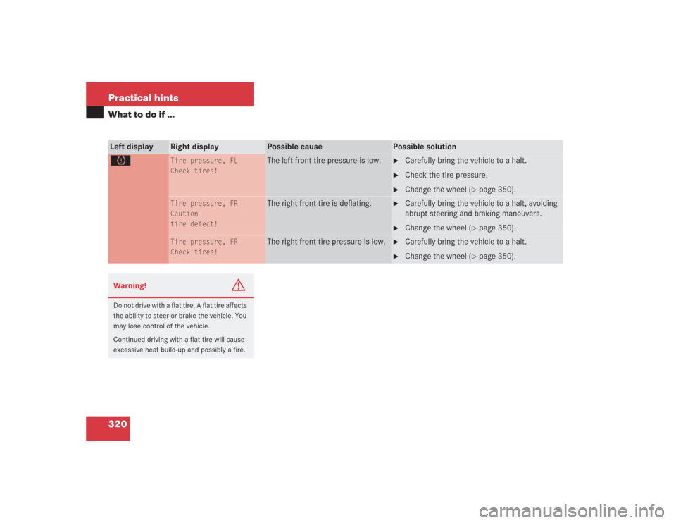
320 Practical hintsWhat to do if …Left display
Right display
Possible cause
Possible solution
H
Tire pressure, FL
Check tires!
The left front tire pressure is low.
�
Carefully bring the vehicle to a halt.
�
Check the tire pressure.
�
Change the wheel (
�page 350).
Tire pressure, FR
Caution
tire defect!
The right front tire is deflating.
�
Carefully bring the vehicle to a halt, avoiding
abrupt steering and braking maneuvers.
�
Change the wheel (
�page 350).
Tire pressure, FR
Check tires!
The right front tire pressure is low.
�
Carefully bring the vehicle to a halt.
�
Change the wheel (
�page 350).
Warning!
G
Do not drive with a flat tire. A flat tire affects
the ability to steer or brake the vehicle. You
may lose control of the vehicle.
Continued driving with a flat tire will cause
excessive heat build-up and possibly a fire.
Page 322 of 434

321 Practical hints
What to do if …
Left display
Right display
Possible cause
Possible solution
H
Reactivate
tire press. monit
.
The tire inflation pressure monitor*
is deactivated.
�
Activate the tire inflation pressure monitor*
(�page 266).
Tire press.
monitor
currently
inactive
The tire inflation pressure monitor*
is temporarily unable to monitor the
tire pressure due to:�
the presence of several wheel
sensors in the vehicle
�
excessive wheel sensor temper-
atures
�
a nearby radio interference
source
�
unrecognized wheel sensors
mounted
�
Remove any additional wheel sensors from
the vehicle, e.g. when transporting a new set
of tires.
As soon as the causes of the malfunction have
been removed, the tire pressure monitor auto-
matically becomes active again.
Warning!
G
Do not drive with a flat tire. A flat tire affects
the ability to steer or brake the vehicle. You
may lose control of the vehicle.
Continued driving with a flat tire will cause
excessive heat build-up and possibly a fire.
Page 323 of 434
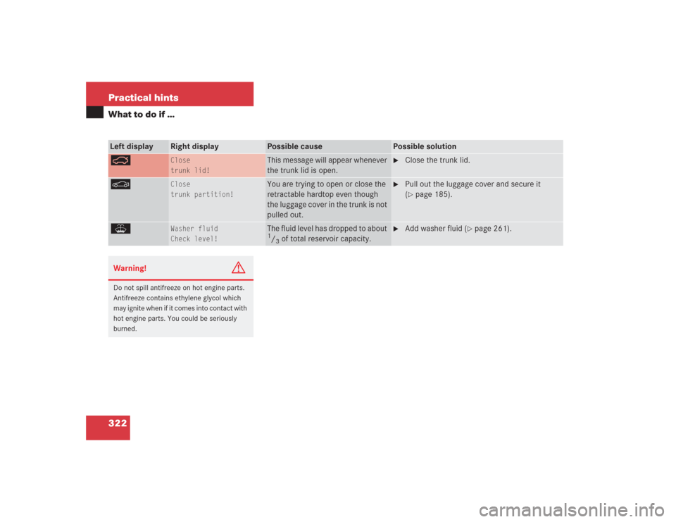
322 Practical hintsWhat to do if …Left display
Right display
Possible cause
Possible solution
Ê
Close
trunk lid!
This message will appear whenever
the trunk lid is open.
�
Close the trunk lid.
M
Close
trunk partition!
You are trying to open or close the
retractable hardtop even though
the luggage cover in the trunk is not
pulled out.
�
Pull out the luggage cover and secure it
(�page 185).
W
Washer fluid
Check level!
The fluid level has dropped to about 1/3 of total reservoir capacity.
�
Add washer fluid (
�page 261).
Warning!
G
Do not spill antifreeze on hot engine parts.
Antifreeze contains ethylene glycol which
may ignite when if it comes into contact with
hot engine parts. You could be seriously
burned.
Page 344 of 434

343 Practical hints
Flat tire
1Flap
2Air hose with pressure gauge and vent
screw
3Union nut
4Electrical plug�
Open flap 1 on air pump.
�
Pull out electrical plug 4 and air hose
with the pressure gauge 2.
�
Screw air hose 2 onto the tire valve.
�
Insert electrical plug 4 into vehicle ci-
gar lighter socket.
�
Turn the SmartKey in the ignition to po-
sition 1 (
�page 31).
or
�
Press the KEYLESS-GO* start/stop
button on the gear selector lever once.
Do not depress brake pedal.
�
Press I on the electric air pump switch.
The electric air pump should now
switch on and inflate the tire.
After 5 minutes, the pressure gauge must
display at least 26 psi (1.8 bar). The air
hose and the union nut can become hot
during inflation. Please exercise appropri-
ate caution.
�
If this tire pressure is not attained, turn
off the electric air pump, detach the air
hose from the tire valve, and again
drive vehicle back and forth very slowly
approximately 30 ft (10 m).
This serves to better distribute the
TIREFIT sealant material inside the tire.
�
Inflate the tire again.
�
Press 0 on the electric air pump switch.
�
Turn the SmartKey in the ignition to
position0.
or
�
Press KEYLESS-GO* start/stop button
on the gear selector lever twice. Do not
depress brake pedal.
The electric air pump should now be
switched off.!Do not operate the electric air pump
longer than eight minutes without in-
terruption. Otherwise it may overheat.
You may operate the air pump again af-
ter it has cooled off.
��
Page 348 of 434

347 Practical hints
Flat tire
�
Screw the air pump’s air hose5 onto
flange6 of the TIREFIT container.
�
Stick TIREFIT container1 upside
down into notch3 of the electric air
pump.
7Tire valve
8Electric air pump switch
9Air hose with pressure gauge and vent
screw
aFiller hose
�
Unscrew the valve cap from tire
valve7.
�
Screw filler hosea onto tire valve7.
�
Insert electrical plug4 into vehicle
cigarette lighter socket.
�
Turn the SmartKey in the starter switch
to position1 (
�page 31).
or
�
Press the KEYLESS-GO* start/stop
button (
�page 33) on the gear selec-
tor lever once. Do not depress brake
pedal.
�
Press I on electric air pump switch8.
The electric air pump should now
switch on and inflate the tire.After 5 minutes, the pressure gauge must
display at least 26 psi (1.8 bar). The air
hose can become hot during inflation.
Please exercise appropriate caution.
�
If this tire pressure is not attained, turn
off the electric air pump, detach the fill-
er hose from the tire valve, and drive
vehicle back and forth very slowly ap-
proximately 30 ft (10 m).
This serves to better distribute the
TIREFIT sealant material inside the tire.
�
Unscrew the air pump’s air hose5
from flange6 of the TIREFIT contain-
er.
�
Screw air hose5onto tire valve7.
�
Inflate the tire again.
Warning!
G
Observe safety instructions on air pump la-
bel.
!Do not operate the electric air pump
longer than eight minutes without in-
terruption. Otherwise it may overheat.
You may operate the air pump again af-
ter it has cooled off.
��
Page 399 of 434

Data bus network serving to control ve-
hicle functions such as door locking or
windshield wiping depending on vehi-
cle settings and/or amb")
398 Technical termsCAN system
(C
ontroller A
rea N
etwork)
Data bus network serving to control ve-
hicle functions such as door locking or
windshield wiping depending on vehi-
cle settings and/or ambient condi-
tions.
Cockpit
All instruments, switches, buttons and
indicator/warning lamps in the passen-
ger compartment needed for vehicle
operation and monitoring.
Collapsible tire
An especially compact spare tire that
must be inflated with a provided air
pump before using. It should only be
used to bring the vehicle to the nearest
service station.
COMAND
(Co
ckpit Man
agement and
D
ata System)
Information and operating center for
vehicle sound and communications
systems, including the radio, CD changer and navigation system, as well
as other optional equipment (e.g. tele-
phone).
Control system
The control system is used to call up
vehicle information and to change
component settings. Information and
messages appear in the multifunction
display. The driver uses the buttons on
the multifunction steering wheel to
navigate through the system and to ad-
just settings.
Cruise control
Driving convenience system for auto-
matically maintaining the vehicle speed
set by the driver.
Distronic*
A driving convenience cruise control
system which helps the driver maintain
a pre-selected speed:
�
If there is no vehicle directly ahead,
the system operates in the same
way as conventional cruise control.
�
If a slower moving vehicle is ahead,
Distronic* will reduce your vehicle
speed to the extent permitted by re-
duced throttle and up to 20% brak-
ing power to maintain the preset
minimum following distance.
DTR
(->Distr
onic*)
Engine number
The number set by the manufacturer
and placed on the cylinder block to
uniquely identify each engine pro-
duced.
ESP
(E
lectronic S
tability P
rogram)
Improves vehicle handling and direc-
tional stability.
ETD
(E
mergency Tensioning D
evice)
Device which deploys in certain frontal
and rear collisions exceeding the sys-
tem's threshold to tighten the seat
belts.
->SRS
Page 400 of 434

Service indicator in the multifunction
display that informs the driver when
the next vehicle maintenance service is
due.
Gear range
Number of ge")
399 Technical terms
FSS
(F
lexible S
ervice S
ystem)
Service indicator in the multifunction
display that informs the driver when
the next vehicle maintenance service is
due.
Gear range
Number of gears which are available to
the automatic transmission for shifting.
The automatic gear shifting process
can be adapted to specific operating
conditions using the gear selector le-
ver.
GPS
(G
lobal P
ositioning S
ystem)
Satellite-based system for relaying
geographic location information to and
from vehicles equipped with special re-
ceivers. Employs CD digital maps for
navigation.Head-thorax airbag
Installed in the doors, these airbags
protect occupants during side impact
collisions exceeding a preset thresh-
old. Unlike normal side airbags,
head-thorax airbags are also designed
to provide protection for the head area.
Instrument cluster
The displays and indicator/warning
lamps in the driver’s field of vision, in-
cluding the tachometer, speedometer,
engine temperature and fuel gauge.
KEYLESS-GO*
System for entering and operating the
vehicle without the use of a key.
Kickdown
Depressing the accelerator past the
point of resistance shifts the transmis-
sion down to the lowest possible gear.
This very quickly accelerates the vehi-
cle and should not be used for normal
acceleration needs.Lock button
Button on the door which indicates
whether the door is locked or un-
locked. Pushing the lock button down
on an individual door from inside will
lock that door.
Memory function
Used to store three individual seat,
steering wheel and mirror positions for
each SmartKey or SmartKey with
KEYLESS-GO*.
MON
The Motor Octane Number for gasoline
as determined by a standardized
method. It is an indication of a gaso-
line's ability to resist undesired detona-
tion (knocking). The average of both
the MON (Motor Octane Number) and
RON (Research Octane Number) is
posted at the pump, also known as
ANTI-KNOCK INDEX.
Page 401 of 434

400 Technical termsMultifunction display
Two display fields in the instrument
cluster used to present information
provided by the control system.
Multifunction steering wheel
Steering wheel with buttons for operat-
ing the control system.
Overspeed range
Engine speeds within the red marking
on the tachometer dial (not on
SL 55 AMG, see “Tachometer”
(
�page 125). Avoid this engine speed
range, as it may result in serious engine
damage that is not covered by the Mer-
cedes-Benz Limited Warranty.
Parktronic*
System which uses visual and acoustic
signals to assist the driver during park-
ing maneuvers.
Poly-V-belt drive
Drives engine-components (alternator,
AC compressor, etc.) from the engine.Power train
Collective term designating all compo-
nents used to generate and transmit
motive power to the drive axles, includ-
ing
�
engine
�
clutch/torque converter
�
transmission
�
transfer case
�
drive shaft
�
differential
�
axle shafts/axlesProgram mode selector switch
Used to switch the automatic transmis-
sion between standard operation (S)
and comfort operation (C).
SL 55 AMG with steering wheel gear-
shift control and manual shift program:
in addition to S and C (for regular S or
comfort C operation, see above), you
can use MANUAL for manual shift pro-
gram
Remote Vehicle Diagnostics
Transmission of vehicle data and cur-
rent location to the Mercedes-Benz
Customer Assistance Center for sub-
scribers to Tele Aid service.
REST
(Residual Engine Heat Utilization)
Feature that uses the engine heat
stored in the coolant to heat the vehi-
cle interior for a short time after the en-
gine has been turned off.