Page 129 of 344
.
The mirrors fold in.Folding out
�
Briefly press button2.
The mirrors fold out.
Windshield wipers
Information on t")
129 Controls in detail
Good visibility
Folding in�
Briefly press button1 (
�page 127).
The mirrors fold in.Folding out
�
Briefly press button2.
The mirrors fold out.
Windshield wipers
Information on the windshield wipers is
found in the “Getting started” section
(�page 49).
!Before you drive the vehicle through an
automatic car wash, fold the exterior
mirrors in, otherwise they may get
damaged.iIf you are driving at more than approxi-
mately 9 mph (15 km / h), you will not
able to fold the exterior mirrors in.
!If an exterior rear view mirror housing
is forcibly pushed forward (hit from the
rear), reposition it manually by applying
firm pressure until it snaps back into
place.
If an exterior rear view mirror is forcibly
pushed rearward (hit from the front)
press button1 to fold mirrors in, then
press button2 to fold mirrors out. Do
not force mirrors by hand as this may
damage the adjustment mechanism.
The mirror housing is now properly po-
sitioned and you can adjust the mirror
normally.
!If leaves, snow, etc. block the wind-
shield wipers, the wiper motor turns
off.�
For safety reasons, withdraw key
from steering lock. Remove block-
age.
�
Turn the windshield wipers on
again.
If windshield wipers fail to function at
all in switch position1,
�
set the wiper switch to the next
highest wiper speed.
�
have the windshield wipers
checked at the nearest authorized
Mercedes-Benz Light Truck Center.
Page 132 of 344
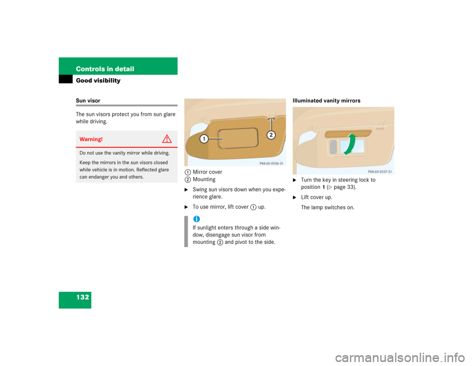
132 Controls in detailGood visibilitySun visor
The sun visors protect you from sun glare
while driving.
1Mirror cover
2Mounting
�
Swing sun visors down when you expe-
rience glare.
�
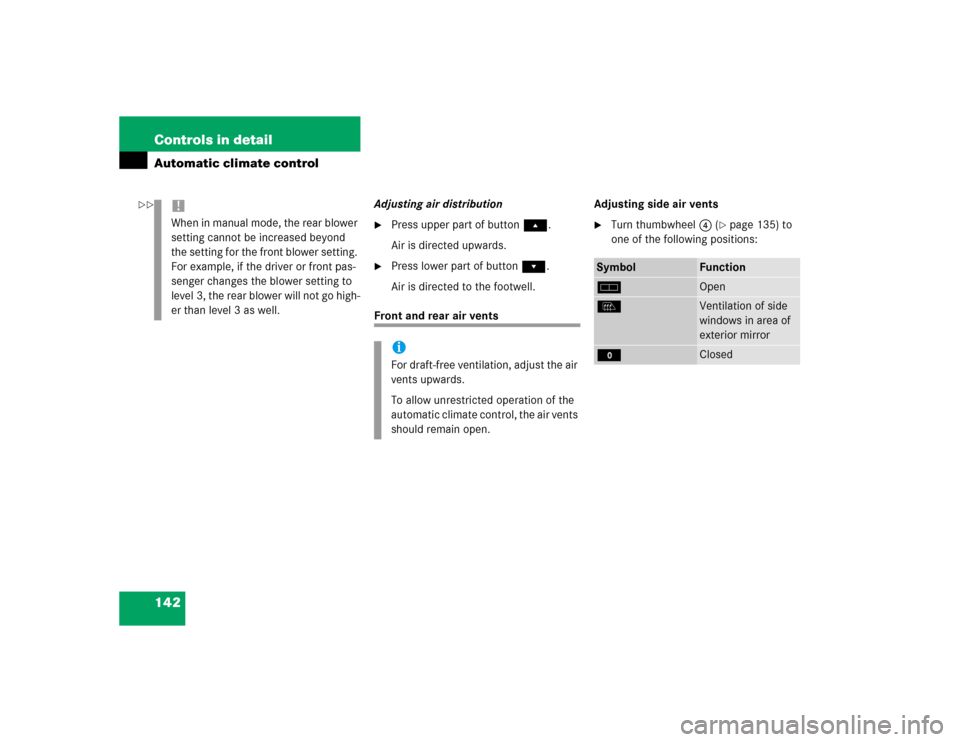
To use mirror, lift cover1 up.Illuminated vanity mirrors
�
Turn the key in steering lock to
position1 (
�page 33).
�
Lift cover up.
The lamp switches on.
Warning!
G
Do not use the vanity mirror while driving.
Keep the mirrors in the sun visors closed
while vehicle is in motion. Reflected glare
can endanger you and others.
iIf sunlight enters through a side win-
dow, disengage sun visor from
mounting2 and pivot to the side.
Page 142 of 344
142 Controls in detailAutomatic climate control
Adjusting air distribution�
Press upper part of buttonÔ.
Air is directed upwards.
�
Press lower part of buttonÓ.
Air is directed to the footwell.
Front and rear air ventsAdjusting side air vents
�
Turn thumbwheel4 (
�page 135) to
one of the following positions:
!When in manual mode, the rear blower
setting cannot be increased beyond
the setting for the front blower setting.
For example, if the driver or front pas-
senger changes the blower setting to
level 3, the rear blower will not go high-
er than level 3 as well.
iFor draft-free ventilation, adjust the air
vents upwards.
To allow unrestricted operation of the
automatic climate control, the air vents
should remain open.
Symbol
Function
h
Open
l
Ventilation of side
windows in area of
exterior mirror
M
Closed
��
Page 173 of 344
 or airbags deploy,
�")
173 Controls in detail
Useful features
Emergency calls
An emergency call is initiated automatical-
ly:�
following an accident in which the
emergency tensioning detractors
(ETDs) or airbags deploy,
�
if the anti-theft alarm or the tow-away
alarm stays on for more than
20 seconds. See anti-theft alarm sys-
tem (
�page 83) and tow-away alarm
(
�page 84).
An emergency call can also be initiated
manually by opening the cover next to the
inside rear view mirror labeled SOS, then
briefly pressing the button located under
the cover. See below for instructions on
initiating an emergency call manually.
Warning!
G
The Tele Aid control unit is located under
the front passenger seat. If there is accumu-
lation of water or other liquid in this area,
the Tele Aid control unit could suffer an
electrical short circuit making the system in-
operative. In this case the indicator lamp in
the SOS button will not illuminate during or
will remain illuminated after the system
self-check. Have the system checked at the
nearest Mercedes-Benz Light Truck Center
as soon as possible.
If the indicator lamps in the SOS button, in
the Roadside Assistance button and / or in
the Information button do not come on dur-
ing the system self-check or if any of these
indicators remain illuminated constantly in
red and / or the message
TELE AID -
VISIT WORKSHOP
is displayed in the MCS
display after the system self-check, a mal-
function in the system has been detected.
If a malfunction is indicated as outlined
above, the system may not operate as ex-
pected. Have the system checked at the
nearest Mercedes-Benz Light Truck Center
as soon as possible.
Page 182 of 344

182 Controls in detailUseful features
Programming or reprogramming the in-
tegrated remote control
Step 1:�
Switch on ignition.
Step 2:
�
If you have previously programmed an
integrated signal transmitter button
and wish to retain its programming,
proceed to step 3. Otherwise, press
and hold the two outer signal transmit-
ter buttons3 and5 and release
them only when the indicator light be-
gins to flash after approximately 20
seconds (do not hold the button for
longer than 30 seconds). This proce-
dure erases any previous settings for
all three channels and initializes the
memory. If you later wish to program a
second and / or third hand-held trans-
mitter to the remaining two signal
transmitter buttons, do not repeat this
step and begin directly with step 3.Step 3:
�
Hold the end of the hand-held remote
control transmitter1 of the device
you wish to train approximately 2 to
5 in (5 to12 cm) away from the surface
of the integrated remote control locat-
ed on the interior rear view mirror,
keeping the indicator lamp6 in view.
Step 4:
�
Using both hands, simultaneously
press the hand-held transmitter
button2 and the desired integrated
signal transmitter button (3, 4
or5). Do not release the buttons until
completing step 5.
The indicator lamp6 on the integrat-
ed remote control will flash, first slowly
and then rapidly.
iFor operation in the USA only:
This device complies with Part 15 of
the FCC Rules. Operation is subject to
the following two conditions:
(1) This device may not cause harmful
interference, and
(2) this device must accept any inter-
ference received, including interfer-
ence that may cause undesired
operation.
Any unauthorized modification to this
device could void the user’s authority
to operate the equipment.
Page 327 of 344
 292
Ignition 33
Immobilizer 83
Activating 54, 83
Deactivating 83
Indicator lamp
Adjustable steering c")
327 Index
I
Identification labels 292
Certification label 292
Vehicle identification number
(VIN) 292
Ignition 33
Immobilizer 83
Activating 54, 83
Deactivating 83
Indicator lamp
Adjustable steering column 253
Brake pad wear 254
Coolant 249
Front fog lamps 253
Low engine oil level 253
Indicators, additional
Speedometer display 256
Infant and child restraint systems 68
Installing 71
LATCH child seat mounts 72Information
About service and warranty 10
Button for Tele Aid* 177
Inside rear view mirror
Antiglare 126
Installing
Infant and child restraint systems 71
Wiper blades 273
Instrument cluster 24, 116, 313
Cleaning 238
Coolant temperature gauge 117
Display in the speedometer 117
Illumination 116
Lamps in 252
Outside temperature indicator 118
Instruments and controls see Cockpit 22
Integrated remote control
Erasing memory 185
Operating 185
Interior lighting 112Activating automatic control 113
Deactivating automatic control 113
Manual operation 113
Reading lamps 114
Interior storage spaces 164
Armrest 165
Cup holder 167
Glove box 164
Storage compartment in front of
armrest 165
Storage compartment under front pas-
senger seat* 164
Intermittent wiping 130
J
Jack 258
Jump starting 281