Page 271 of 344
271 Practical hints
Replacing bulbs
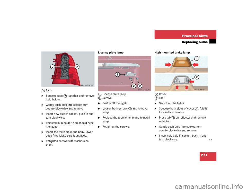
7Tabs�
Squeeze tabs7 together and remove
bulb holder.
�
Gently push bulb into socket, turn
counterclockwise and remove.
�
Insert new bulb in socket, push in and
turn clockwise.
�
Reinstall bulb holder. You should hear
it engage.
�
Insert the tail lamp in the body, lower
edge first. Make sure it engages.
�
Retighten screws with washers on
them.License plate lamp
1License plate lamp
2Screws
�
Switch off the lights.
�
Loosen both screws2 and remove
lamp.
�
Replace the tubular lamp and reinstall
lamp.
�
Retighten the screws.High mounted brake lamp
1Cover
2Tab
�
Switch off the lights.
�
Squeeze both sides of cover1, fold it
forward and remove.
�
Press tab2 on reflector and remove
reflector.
�
Gently push bulb into socket, turn
counterclockwise and remove.
�
Insert new bulb in socket, push in and
turn clockwise.
��
Page 272 of 344

272 Practical hintsReplacing bulbs�
Insert reflector from the left so that it
engages on the right.
�
Position tabs of cover in slots and rein-
stall cover until properly seated.
Adjusting headlamp aim
VVertical centerline
HHeadlamp mounting high, measured
from the centerCorrect headlamp adjustment is extremely
important. To check and readjust a head-
lamp, follow the steps described:
�
Park the vehicle on a level surface
25 feet (7.6 m) from a vertical test
screen or wall.
�
Switch the headlamps on
(�page 110).
If the beam does not show a beam pattern
as indicated in the figure left, then follow
the steps below:
�
Open hood (
�page 217).
2Headlamp vertical adjustment screw
3Headlamp vertical adjustment screw
�
Always turn adjustment screws2
and3 simultaneously for vertical ad-
justment until the headlamp is adjust-
ed as shown1. Turn clockwise for
upward movement and counterclock-
wise for downward movement.
Graduations:
screw2: 0.50° pitch
screw3: 0.67° pitch
The left and right headlamps must be ad-
justed individually.
iHigh beam adjustments simultaneous-
ly aim the low beam.
Vehicle should have a normal trunk
load.
iIf it is not possible to obtain a proper
headlamp adjustment, have the system
checked at your authorized
Mercedes-Benz Light Truck Center.
��
Page 274 of 344

274 Practical hintsFlat tire
�Flat tireMounting the spare wheel Preparing the vehicle
�
Park the vehicle as far as possible from
moving traffic on a hard surface.
�
Turn on the hazard warning flashers.
�
Engage the steering wheel lock in the
straight ahead position and set the
parking brake.
�
Move the gear selector lever toP.
�
Have any passenger exit the vehicle at
a safe distance from the roadway.
�
Take the spare wheel out of its carrier
(�page 259).Lifting the vehicle
�
Prevent the vehicle from rolling away
by blocking wheels with wheel chocks
(not included) or other sizable objects.
When changing wheel on a level surface:
�
Place one chock in front of and one be-
hind the wheel that is diagonally oppo-
site to the wheel being changed.
When changing wheel on a hill:
�
Place chocks on the downhill side
blocking both wheels of the other axle.
�
Take the two-piece wheel wrench and
the jack out of the rear compartment
area (
�page 257). Assemble wheel
wrench.
Warning!
G
The dimensions of the spare wheel are dif-
ferent from those of the road wheels. As a
result, the vehicle handling characteristics
change when driving with a mounted spare
wheel. Adapt your driving style accordingly.
The spare wheel is for temporary use only.
When driving with spare wheel mounted, en-
sure proper tire pressure and do not exceed
vehicle speed of 50 mph (80 km / h).
Drive to the nearest Mercedes-Benz Light
Truck Center as soon as possible to have the
spare wheel replaced with a regular road
wheel.
Never operate the vehicle with more than
one spare wheel mounted.
Page 276 of 344

276 Practical hintsFlat tireRemoving the wheel�
Unscrew and remove all wheel bolts.
�
Remove the remaining bolts.
�
Grip the wheel from the sides and re-
move it.
Mounting the new wheel
�
Clean contact surfaces of wheel and
wheel hub.
�
Install spare wheel on wheel hub.
�
Insert wheel bolts and tighten them
slightly.Lowering the vehicle
�
Lower vehicle by turning crank coun-
terclockwise until vehicle is resting ful-
ly on its own weight.
�
Remove the jack.
!Do not place wheel bolts in sand or dirt.
This could result in damage to the bolt
and wheel hub threads.!To avoid paint damage, place wheel flat
against hub and hold it there while in-
stalling first wheel bolt.
Warning!
G
Always replace wheel bolts that are dam-
aged or rusted.
Never apply oil or grease to wheel bolts.
Damaged wheel hub threads should be re-
paired immediately. Do not continue to drive
under these circumstances! Contact an au-
thorized Mercedes-Benz Light Truck Center
or call Roadside Assistance.
Incorrect wheel bolts or improperly tight-
ened wheel bolts can cause the wheel to
come off. This could cause an accident.
Make sure to use the correct wheel bolts.
Warning!
G
Use only genuine equipment
Mercedes-Benz wheel bolts. Other wheel
bolts may come loose.
Do not tighten the wheel bolts when the ve-
hicle is raised. Otherwise the vehicle could
tip over.
Page 278 of 344

278 Practical hintsBattery
�BatteryThe battery is located on the passenger
side of the engine compartment.
1Negative terminal
2Positive terminal
Warning!
G
Failure to follow these instructions can re-
sult in severe injury or death.
Observe all safety instructions and precau-
tions when handling automotive batteries
(�page 223).
Never lean over batteries while connecting,
you might get injured.
Battery fluid contains sulfuric acid. Do not
allow this fluid to come in contact with eyes,
skin or clothing. In case it does, immediately
flush affected area with water and seek
medical help if necessary.
A battery will also produce hydrogen gas,
which is flammable and explosive. Keep
flames or sparks away from battery, avoid
improper connection of jumper cables,
smoking etc.
!Never loosen or detach battery termi-
nal clamps while the engine is running
or the key is in the steering lock. Other-
wise the alternator and other electronic
components could be severely dam-
aged.
Have the battery checked regularly by
an authorized Mercedes-Benz Light
Truck Center.
Refer to Service Booklet for mainte-
nance intervals or contact your autho-
rized Mercedes-Benz Light Truck
Center for further information.Warning!
G
Do not place metal objects on the battery as
this could result in a short circuit.
Use leak-proof battery only to avoid the risk
of acid burns in the event of an accident.
Page 281 of 344

281 Practical hints
Jump starting
�Jump starting
If the battery is discharged, the engine can
be started with jumper cables and the bat-
tery of another vehicle. Observe the follow-
ing:�
Jump starting should only be performed
when the engine and catalytic convert-
er are cold.
�
Do not start the engine if the battery is
frozen. Let the battery thaw out first.
�
Only jump start from batteries with the
same voltage rating (12 V). Jump start-
ing with a more powerful battery could
damage the vehicle's electrical system,
which will not be covered by the
Mercedes-Benz Limited Warranty.
�
Use only jumper cables with sufficient-
cross-section and insulated terminal
clamps.
�
Always make sure the jumper cables
are not on or near pulleys, fans or other
parts that move when the engine is
started or running.
Warning!
G
Failure to follow these directions will cause
damage to the electronic components, and
can lead to a battery explosion and severe
injury or death.
Never lean over batteries while connecting
or jump starting, you might get injured.
Battery fluid contains sulfuric acid. Do not
allow this fluid to come in contact with eyes,
skin or clothing. In case it does, immediately
flush affected area with water, and seek
medical help if necessary.
A battery will also produce hydrogen gas,
which is flammable and very explosive. Keep
flames or sparks away from battery, avoid
improper connection of jumper cables,
smoking, etc.
Attempting to jump start a frozen battery
can result in it exploding, causing personal
injury.
Read all instructions before proceeding.
!Avoid repeated and lengthy starting at-
tempts.
Do not attempt to start the engine us-
ing a battery quick charge unit.
If engine does not run after several un-
successful starting attempts, have it
checked at the nearest authorized
Mercedes-Benz Light Truck Center.
Excessive unburned fuel generated by
repeated failed starting attempts may
damage the catalytic converter and
may present a fire risk.
Make sure the jumper cables do not
have loose or missing insulation.
Make sure the cable clamps do not
touch any other metal part while the
other end is still attached to a battery.
Page 282 of 344

282 Practical hintsJump startingThe battery is located on the right side of
the engine compartment.�
Make sure the two vehicles do not
touch.
�
Turn off all electrical consumers.
�
Apply parking brake.
�
Shift gear selector lever to positionP.
�
Open the hood.
�
Connect positive terminals1 and4
of the batteries with the jumper cable.
Clamp cable to positive terminal4 of
charged battery first.1Positive terminal of discharged battery
2Negative terminal of discharged
battery
3Negative terminal of charged battery
4Positive terminal of charged battery
�
Start engine of the vehicle with the
charged battery and run at idle speed.
�
Connect negative terminals2 and3
of the batteries with the jumper cable.
Clamp cable to negative terminal3 of
charged battery first.
�
Start the engine of the disabled vehi-
cle.
Now you can turn on the electrical
consumers. Do not turn on the lights under
any circumstances.
�
Remove the jumper cables first from
the negative terminals2 and3 and
then from positive terminals1
and4.
You can now turn on the lights.
�
Have the battery checked at the
nearest authorized Mercedes-Benz
Light Truck Center.
Warning!
G
Keep flames or sparks away from battery.
Do not smoke.
Observe all safety instructions and precau-
tions when handling automotive batteries
(�page 223).
!Never invert the terminal connections.
!Do not tow-start the vehicle.
Page 287 of 344
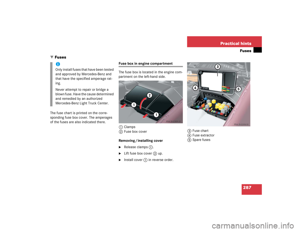
287 Practical hintsFuses
�Fuses
The fuse chart is printed on the corre-
sponding fuse box cover. The amperages
of the fuses are also indicated there.
Fuse box in engine compartment
The fuse box is located in the engine com-
partment on the left-hand side.
1Clamps
2Fuse box cover
Removing / installing cover�
Release clamps1.
�
Lift fuse box cover2 up.
�
Install cover1 in reverse order.3Fuse chart
4Fuse extractor
5Spare fuses
iOnly install fuses that have been tested
and approved by Mercedes-Benz and
that have the specified amperage rat-
ing.
Never attempt to repair or bridge a
blown fuse. Have the cause determined
and remedied by an authorized
Mercedes-Benz Light Truck Center.