Page 86 of 344
86 Safety and SecurityAnti-theft systemsVehicles without trip computer
The buttons are located in the overhead
control panel.
1Switching off tow-away alarm and glass
breakage sensor
�
Turn key in steering lock to position2
(�page 33).
�
Return key to position0 and remove it
from the steering lock.
�
Within 30 seconds press button1 on
the right or left side.
�
Exit vehicle and lock vehicle with
remote control (
�page 32).
The tow-away alarm and glass breakage
sensor remain switched off until the key is
inserted in steering lock and turned to
position1.Canceling the alarm
To cancel the alarm:
�
Switch on the ignition by turning the
key in the steering lock to position2.
or
�
Press theŒ or ‹button on the
remote control.
The alarm is canceled.
Page 89 of 344

89 Controls in detail
Locking and unlocking
Unlocking
Unlocking the driver’s door and fuel
filler flap�
Press buttonΠonce.
All turn signal lamps flash once to indi-
cate that the driver’s door and the fuel
filler flap are unlocked.Global unlocking
�
Press buttonΠtwice.
All turn signal lamps flash once to indi-
cate that all doors, fuel filler flap and
liftgate are unlocked.
Unlocking the liftgate
�
Press buttonŠ.
Only the liftgate unlocks.
Locking
�
Press button‹ once.
All turn signal lamps flash three times
to indicate that all doors, the liftgate
and the fuel filler flap are locked.
iUnlocking the vehicle with the remote
control deactivates the anti-theft
alarm.
The vehicle will lock again automatical-
ly and reactivate the anti-theft system
within approximately 40 seconds of un-
locking if neither door nor liftgate is
opened.
iLocking the vehicle with the remote
control activates the anti-theft alarm.
iIf the turn signal lamps do not flash
three times, one of the following ele-
ments may not be properly closed:�
a door
�
the liftgate
�
the hood
Close the respective element and lock
the vehicle again.
Warning!
G
When leaving the vehicle, always remove the
key from the steering lock, and lock your ve-
hicle. Do not leave children unattended in
the vehicle, or with access to an unlocked
vehicle. Unsupervised use of vehicle equip-
ment may cause an accident and / or seri-
ous personal injury.
Page 91 of 344
91 Controls in detail
Locking and unlocking
Opening the liftgate
Opening the liftgate from outside
A minimum height clearance of 7 ft
(2.15 m) is required to open the liftgate.
The handle is located above the rear
license plate recess.
1Grip molding
2Handle�
Pull on handle2.
�
Swing the liftgate upward by using the
grip molding.Opening the liftgate from inside
A minimum height clearance of 7 ft
(2.15 m) is required to open the liftgate.
The release lever is located on the inside of
the liftgate.
1Handle
2Catch
iIf the vehicle has previously been
locked from the outside with the re-
mote control, opening a door from the
inside will trigger the alarm.
To cancel the alarm, do one of the
following:
Switch on the ignition by turning the
key in the steering lock to position2.
or
Press the‹ or Œbutton on the
remote control.
The alarm is cancelled.
!Always make sure that there is suffi-
cient overhead clearance.iThe vehicle must be unlocked.
Page 172 of 344

The Tele Aid system consists of three
types of response:�
automatic and manual emergency
�
roadsid")
172 Controls in detailUseful featuresThe Tele Aid system
(Telematic Alarm Identification on
Demand)
The Tele Aid system consists of three
types of response:�
automatic and manual emergency
�
roadside assistance and
�
information.
The Tele Aid system is operational provid-
ing that the vehicle’s battery is charged,
properly connected, not damaged and cel-
lular and GPS coverage is available.
The speaker volume of a Tele Aid call can
be adjusted using the volume control on
the MCS unit.
�
To activate, press the SOS button, the
Roadside Assistance button• or
the Information button¡, depend-
ing on the type of response required.Shortly after the completion of your ac-
quaintance call, you will receive a user ID
and password via first call mail. By visiting
www.mbusa.com and selecting “Tele Aid”
(USA only), you will have access to account
information, remote door unlock, profile
and more.System self-check
Initially, after turning the key in the steer-
ing lock to position2, malfunctions are de-
tected and indicated (the indicator lamps
in the SOS button, the Roadside Assis-
tance button• and the Information
button¡ stay on longer than
10 seconds or do not come on). The mes-
sage
TELE AID - VISIT WORKSHOP
ap-
pears for approx. 10 seconds in the MCS
display.
iThe SOS button, the Roadside Assis-
tance button• and the Information
button¡ are located in the over-
head control panel.!The Tele Aid system utilizes the cellular
network for communication and the
GPS (G
lobal P
ositioning S
ystem) satel-
lites for vehicle location. If either of
these signals are unavailable, the Tele
Aid system may not function and if this
occurs, assistance must be summoned
by other means.
Page 173 of 344
 or airbags deploy,
�")
173 Controls in detail
Useful features
Emergency calls
An emergency call is initiated automatical-
ly:�
following an accident in which the
emergency tensioning detractors
(ETDs) or airbags deploy,
�
if the anti-theft alarm or the tow-away
alarm stays on for more than
20 seconds. See anti-theft alarm sys-
tem (
�page 83) and tow-away alarm
(
�page 84).
An emergency call can also be initiated
manually by opening the cover next to the
inside rear view mirror labeled SOS, then
briefly pressing the button located under
the cover. See below for instructions on
initiating an emergency call manually.
Warning!
G
The Tele Aid control unit is located under
the front passenger seat. If there is accumu-
lation of water or other liquid in this area,
the Tele Aid control unit could suffer an
electrical short circuit making the system in-
operative. In this case the indicator lamp in
the SOS button will not illuminate during or
will remain illuminated after the system
self-check. Have the system checked at the
nearest Mercedes-Benz Light Truck Center
as soon as possible.
If the indicator lamps in the SOS button, in
the Roadside Assistance button and / or in
the Information button do not come on dur-
ing the system self-check or if any of these
indicators remain illuminated constantly in
red and / or the message
TELE AID -
VISIT WORKSHOP
is displayed in the MCS
display after the system self-check, a mal-
function in the system has been detected.
If a malfunction is indicated as outlined
above, the system may not operate as ex-
pected. Have the system checked at the
nearest Mercedes-Benz Light Truck Center
as soon as possible.
Page 261 of 344
261 Practical hints
Unlocking / locking in an emergency
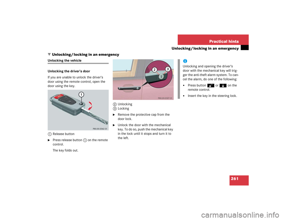
�Unlocking / locking in an emergency
Unlocking the vehicle
Unlocking the driver’s door
If you are unable to unlock the driver’s
door using the remote control, open the
door using the key.
1Release button�
Press release button1 on the remote
control.
The key folds out.2Unlocking
3Locking
�
Remove the protective cap from the
door lock.
�
Unlock the door with the mechanical
key. To do so, push the mechanical key
in the lock until it stops and turn it to
the left.
iUnlocking and opening the driver’s
door with the mechanical key will trig-
ger the anti-theft alarm system. To can-
cel the alarm, do one of the following:�
Press buttonŒ or‹ on the
remote control.
�
Insert the key in the steering lock.
Page 283 of 344

283 Practical hints
Towing the vehicle
�Towing the vehicle
Mercedes-Benz recommends that the vehi-
cle be transported with all wheels off the
ground using flatbed or appropriate wheel
lift / dolly equipment. This method is pref-
erable to other types of towing.When circumstances do not permit the
recommended towing methods, the vehi-
cle may be towed with all wheels on the
ground only so far as necessary to have the
vehicle moved to a safe location where the
recommended towing methods can be em-
ployed.
!Use flatbed or wheel lift / dolly equip-
ment, with key in steering lock turned
to position0.
Do not tow with sling-type equipment.
Towing with sling-type equipment over
bumpy roads will damage radiator and
supports.
To prevent damage during transport,
do not tie down vehicle by its chassis or
suspension parts. Use the towing eyes.
Switch off the ESP (
�page 81),
tow-away alarm (
�page 85) and the
automatic central locking (
�page 93).
!When towing the vehicle with all wheels
on the ground, the gear selector lever
must be in positionN and the key must
be in steering lock position2.
When towing the vehicle with all wheels
on the ground, the vehicle may be
towed only for distances up to 30 miles
(50 km) and at a speed not to exceed
30 mph (50 km / h).
If the vehicle is towed with the front
axle raised (observe instructions re-
garding flexible drive shaft), the engine
must be shut off (key in steering lock
position1). Otherwise, the 4-ETS may
become engaged which may cause loss
of towing control.
!To be certain to avoid additional dam-
age to the vehicle powertrain, however
you should observe the following:�
With damage to the front axle�
raise front axle
�
remove flexible drive shaft be-
tween rear axle and transfer
case
�
With damage to the rear axle�
raise rear axle
�
tow vehicle with wheel lift or
dolly placed under front wheels
�
With damage to the transfer case�
remove flexible drive shaft to
the drive axles
Always install new self-locking nuts
when reinstalling flexible drive shaft.
Page 317 of 344

317 Index
A
ABS 25, 76, 311
ABS control 76
LOW RANGE mode 77
Malfunction indicator lamp 242
Warning lamp 242
Accelerator position, automatic
transmission 123
Accident
In case of 52
Activating
Air circulation mode 139
Air recirculation mode 139
Anti-theft alarm system 83
Automatic climate control 135
ESP 82
Exterior headlamps 48
Hazard warning flasher 112
Headlamps 48
High beams 110
Ignition 33Immobilizer 54, 83
Rear passenger compartment ventila-
tion and climate control 141
Rear window defroster 133
Rear window wiper 51
Residual heat 140
Seat heater* 98
Tow-away alarm 85
Warning indicators (Parktronic*) 155
Windshield wipers 50
Activating automatic central locking 93
Adding
Coolant 223
Engine oil 221
Additional turn signals 266
Adjustable steering column
Indicator lamp 253
Adjusting 34
Backrest tilt 36, 38
Exterior rear view mirror 40
Head restraint height 36, 38Head restraint tilt 37, 39
Headlamp aim 272
Instrument cluster illumination 116
Manual seat 35
Mirrors 40
Power seats* 37
Seat cushion tilt 38
Seat fore and aft 35
Seat fore and aft adjustment 37
Seat height 36, 38
Seats 34
Steering wheel 39
Adjusting air distribution
Automatic climate control 137
Adjusting air volume
Automatic climate control 137
Air conditioner (cooling)
Turning on 139
Air conditioning
Cooling 139

 is required to open the liftgate.
The handle is located")