Page 25 of 376
25 At a glance
Instrument cluster
Item
Page
1
Reset button for:�
Resetting trip odometer
113
�
Resetting individual or
all settings
123,
125,
137,
243
�
Instrument cluster illu-
mination
112
2
LLeft turn signal indi-
cator lamp
24
3
?Engine malfunction
indicator lamp
256
vElectronic Stability
Program (ESP) warn-
ing lamp
78,
257
AHigh beam head-
lamp indicator
47,
108
Item
Page
4
KRight turn signal in-
dicator lamp
24
5
Fuel gauge with:Fuel reserve warning lamp
24
1Supplemental Re-
straint System (SRS)
indicator lamp
60,
258
warning lamp
62,
258
6
Multifunction display
with:
115
Trip odometer
24
Main odometer
24
Transfer case program
mode
145
Gear selector lever position
140
Outside temperature indi-
cator
114
Clock (see COMAND oper-
ating instructions)
115
Item
Page
7
Speedometer
8
Tachometer with:;Brake warning lamp
(USA only)
44,
254
3Brake warning lamp
(Canada only)
44,
254
-ABS indicator lamp
74,
252
Page 91 of 376
.
�
Pull the mechanical key out of the
SmartKey (
�page 287).
�
Insert the mechanical key in the lock
cylinder.
�
Turn the")
91 Controls in detail
Locking and unlocking
�
Close the tailgate (
�page 90).
�
Pull the mechanical key out of the
SmartKey (
�page 287).
�
Insert the mechanical key in the lock
cylinder.
�
Turn the mechanical key clockwise to
position2.
The tailgate remains locked even when the
vehicle is centrally unlocked.
Separately unlocking the tailgate�
Pull the mechanical key out of the
SmartKey (
�page 287).
�
Insert the mechanical key in the lock
cylinder.
�
Turn the mechanical key to neutral
position1 (
�page 90).
You can now open the tailgate
(
�page 89).
Automatic central locking
The doors and the tailgate automatically
lock when the ignition is switched on and
the wheels are turning at vehicle speeds of
approximately 9 mph (15 km/h) or more.
You can open a locked door from the in-
side. Open door only when conditions are
safe to do so.
iYou can only cancel the separate tail-
gate locking mode by means of the me-
chanical key.
Warning!
G
Only drive with the tailgate closed as other-
wise exhaust fumes may enter the vehicle
interior.
Page 112 of 376
.
1Reset button")
112 Controls in detailInstrument cluster
�Instrument clusterA full view illustration of the instrument
cluster can be found in the “At a glance”
section of this manual (
�page 24).
1Reset button
The instrument cluster is activated when
you:
�
open a door
�
turn on the ignition
�
press reset button1
�
switch on the exterior lamps
You can change the instrument cluster set-
tings in the Instrument cluster submenu of
the control system (
�page 127).
Instrument cluster illumination
Use the reset button to adjust the illumina-
tion brightness for the instrument cluster.
To brighten illumination�
Turn reset button1 in the instrument
cluster clockwise.
The instrument cluster illumination will
brighten.To dim illumination
�
Turn reset button1 in the instrument
cluster counterclockwise.
The instrument cluster illumination will
dim.
Coolant temperature display
iThe instrument cluster illumination is
dimmed or brightened automatically to
suit ambient light conditions.
The instrument cluster illumination will
also be adjusted automatically when
you switch on the vehicle’s exterior
lamps.
Warning!
G
�
Driving when your engine is badly over-
heated can cause some fluids which
may have leaked into the engine com-
partment to catch fire. You could be se-
riously burned.
�
Steam from an overheated engine can
cause serious burns and can occur just
by opening the hood. Stay away from
the engine if you see or hear steam com-
ing from it.
Turn off the engine, get out of the vehicle
and do not stand near the vehicle until the
engine has cooled down.
Page 115 of 376

115 Controls in detail
Control system
�Control system
The control system is activated as soon as
the SmartKey in the starter switch is
turned to position1. The control system
enables you to�
call up information about your vehicle
�
change vehicle settings
For example, you can use the control sys-
tem to find out when your vehicle is next
due for service, to set the language for
messages in the instrument cluster display
and much more.
The control system relays information to
the multifunction display.
Multifunction display
1Trip odometer
2Main odometer
3Outside temperature
4Clock
1
5Current gear selector lever position
6Transfer case program mode
Warning!
G
A driver’s attention to the road and traffic
conditions must always be his /her primary
focus when driving.
For your safety and the safety of others, se-
lecting features through the multifunction
steering wheel should only be done by the
driver when traffic and road conditions per-
mit it to be done safely.
Bear in mind that at a speed of just 30 mph
(approximately 50 km/h), your vehicle is
covering a distance of 44 feet (approximate-
ly 13.5 m) every second.
1See separate operating instructions for the
COMAND system for clock setting.
Page 287 of 376

287 Practical hints
Unlocking/locking in an emergency
�Unlocking/locking in an emergency
Unlocking the vehicle
If you are unable to unlock the vehicle with
the SmartKey, open the driver’s door and
the tailgate using the mechanical key.
The passenger door cannot be unlocked
manually.
1Mechanical key locking tab
2Mechanical key
�
Move locking tab1 in direction of ar-
row and slide the mechanical key2
out of the housing.
Unlocking the driver’s door
�
Unlock the door with the mechanical
key. To do so, push the mechanical key
in the lock until it stops and turn it to
the left.Unlocking the tailgate
If you are unable to unlock the tailgate with
the SmartKey, open the tailgate with the
mechanical key as follows:
1Unlocking in an emergency
2Lock cylinder
3Handle
�
Insert the mechanical key into the tail-
gate lock.
�
Turn the mechanical key counterclock-
wise to position1 and hold it in this
position.
iUnlocking your vehicle with the me-
chanical key will trigger the anti-theft
alarm system. To cancel the alarm, do
one of the following:�
Press button Œ or ‹ on the
SmartKey.
�
Insert the SmartKey in the starter
switch.
��
Page 292 of 376
292 Practical hintsOpening/closing in an emergency
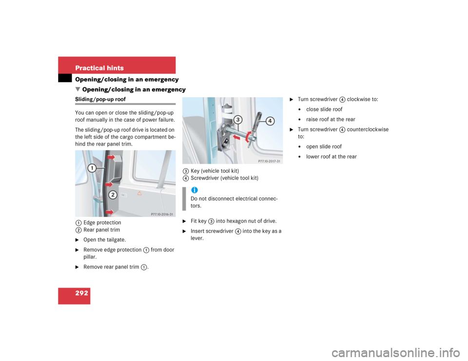
�Opening/closing in an emergencySliding/pop-up roof
You can open or close the sliding/pop-up
roof manually in the case of power failure.
The sliding/pop-up roof drive is located on
the left side of the cargo compartment be-
hind the rear panel trim.
1Edge protection
2Rear panel trim�
Open the tailgate.
�
Remove edge protection1 from door
pillar.
�
Remove rear panel trim1.3Key (vehicle tool kit)
4Screwdriver (vehicle tool kit)
�
Fit key3 into hexagon nut of drive.
�
Insert screwdriver4 into the key as a
lever.
�
Turn screwdriver4 clockwise to:�
close slide roof
�
raise roof at the rear
�
Turn screwdriver4 counterclockwise
to:�
open slide roof
�
lower roof at the rear
iDo not disconnect electrical connec-
tors.
Page 298 of 376
298 Practical hintsReplacing bulbs1Protection cover
2Electrical connector (parking and
standing lamps)
3Electrical connector (high and low
beam)4Retainer spring
5Bulb for high and low beam
6Bulb socket for parking and standing
lamps
High and low beam bulb
�
Remove protection cover1.
�
Pull off electrical connector3.
�
Unclip retainer spring4.
�
Remove bulb5.
�
Insert new bulb so that the base lo-
cates in the recess on the holder.
�
Clip in retainer spring4.
�
Plug electrical connector3 onto
bulb5.
�
Press on protection cover1.
Parking and standing lamp bulb
�
Pull off electrical connector2 from
bulb socket6.
�
Push bulb into bulb socket6, turn
counterclockwise and remove.
�
Insert new bulb in bulb socket6, push
in and turn clockwise until it clicks in.
�
Plug electrical connector2 onto bulb
socket6.
Page 300 of 376
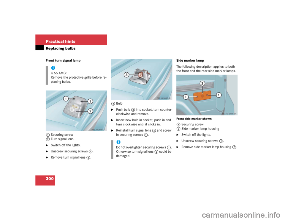
300 Practical hintsReplacing bulbsFront turn signal lamp
1Securing screw
2Turn signal lens�
Switch off the lights.
�
Unscrew securing screws1.
�
Remove turn signal lens2.3Bulb
�
Push bulb3 into socket, turn counter-
clockwise and remove.
�
Insert new bulb in socket, push in and
turn clockwise until it clicks in.
�
Reinstall turn signal lens2 and screw
in securing screws1.Side marker lamp
The following description applies to both
the front and the rear side marker lamps.
Front side marker shown1Securing screw
2Side marker lamp housing�
Switch off the lights.
�
Unscrew securing screws1.
�
Remove side marker lamp housing2.
iG55AMG:
Remove the protective grille before re-
placing bulbs.
iDo not overtighten securing screws1.
Otherwise turn signal lens2 could be
damaged.


3Electrical connector (high and low
beam)4Retainer spring
5Bulb for high and low beam
6Bulb soc")