Page 77 of 442
77 Safety and Security
Driving safety systems
More information can be found in the
“Practical hints” section (
�page 311).
Warning!
G
Never switch off the ESP when you see the
ABS/ESP warning lamp v fl as h in g i n t he
instrument cluster. In this case proceed as
follows:�
While driving off, apply as little throttle
as possible.
�
While driving, ease up on the accelera-
tor.
�
Adapt your speed and driving style to
the prevailing road conditions.
Failure to observe these guidelines could
cause the vehicle to skid.
The ESP cannot prevent accidents resulting
from excessive speed.
Warning!
G
The ESP cannot prevent the natural laws of
physics from acting on the vehicle, nor can
it increase the traction afforded. The ESP
cannot prevent accidents, including those
resulting from excessive speed in turns, or
hydroplaning. Only a safe, attentive, and
skillful driver can prevent accidents. The ca-
pabilities of an ESP equipped vehicle must
never be exploited in a reckless or danger-
ous manner which could jeopardize the us-
er’s safety or the safety of others.!The ESP will only function properly if
you use wheels of the recommended
tire size (
�page 394).
!Vehicles without 4MATIC:
Because of the ESP’s automatic opera-
tion, the engine and ignition must be
shut off (SmartKey in starter switch
position0 or1 or KEYLESS-GO
start/stop button* in position0 or1)
when: �
the parking brake is being tested on
a brake test dynamometer
�
the vehicle is being towed with the
front axle raised
Active braking action through the ESP
may otherwise seriously damage the
brake system.
For information on vehicles with
4MATIC, see “Four wheel electronic
traction system (4MATIC) with the
ESP” (
�page 82).
Page 78 of 442
78 Safety and SecurityDriving safety systemsSwitching off the ESP
To improve the vehicle's traction, turn off
the ESP in driving situations where it would
be advantageous to have drive wheels spin
and thus cut into surfaces for better grip
such as:�
s t a r t i n g o u t o n s l i p p e r y s u r f a c e s a n d i n
deep snow in conjunction with snow
chains
�
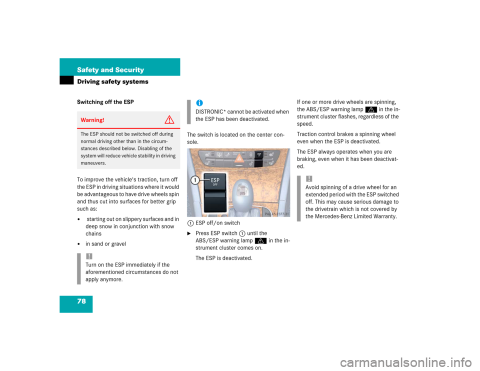
in sand or gravelThe switch is located on the center con-
sole.
1ESP off/on switch
�
Press ESP switch 1 until the
ABS/ESP warning lamp v in the in-
strument cluster comes on.
The ESP is deactivated.If one or more drive wheels are spinning,
the ABS/ESP warning lamp v in the in-
strument cluster flashes, regardless of the
speed.
Traction control brakes a spinning wheel
even when the ESP is deactivated.
The ESP always operates when you are
braking, even when it has been deactivat-
ed.
Warning!
G
The ESP should not be switched off during
normal driving other than in the circum-
stances described below. Disabling of the
system will reduce vehicle stability in driving
maneuvers.!Turn on the ESP immediately if the
aforementioned circumstances do not
apply anymore.
iDISTRONIC* cannot be activated when
the ESP has been deactivated.
!Avoid spinning of a drive wheel for an
extended period with the ESP switched
off. This may cause serious damage to
the drivetrain which is not covered by
the Mercedes-Benz Limited Warranty.
Page 79 of 442
79 Safety and Security
Driving safety systems
Switching on the ESP�
Press ESP button1.
The ABS/ESP warning lamp v in
the instrument cluster goes out.
You are now again in normal driving
mode.
The SBC brake system
The SBC brake system combines a hydrau-
lic brake circuit with electronically con-
trolled brake servo assistance. You have
increased braking safety and improved
braking comfort.
Warning!
G
When the ABS/ESP warning lamp v is
illuminated continuously, the ESP is
switched off.
Adapt your speed and driving to the prevail-
ing road conditions and to the non-operating
status of the ESP.!Turn on the ESP immediately if the
aforementioned circumstances do not
apply anymore.
Warning!
G
Never ignore a brake malfunction indicated
in the speedometer display, for example by
the ; (USA only) or 3 (Canada only)
warning lamp. Refer to the “Practical hints”
section (
�page 312). Also read and ob-
serve the messages in the instrument clus-
ter display (�page 318).
Warning!
G
The SBC brake system requires electrical
power to operate.
A malfunction in the vehicle’s power supply
or electrical system may impair brake sys-
tem operation and switch it into its emer-
gency operation mode. In such a case, the
red brake warning lamp (
�page 312) and
warning messages in the instrument cluster
(
�page 318) come on while driving. To
brake, the driver must then apply signifi-
cantly greater brake pedal pressure and de-
press the pedal much further to obtain the
expected braking effect. If necessary, apply
full pressure to the brake pedal. Brakes may
only be applied to the front wheels. Stop-
ping distance is increased!
��
Page 80 of 442
80 Safety and SecurityDriving safety systems
The SBC brake system is automatically ac-
tivated when you:�
unlock the vehicle with the SmartKey
or the KEYLESS-GO*
�
open the driver’s or passenger door
�
turn the SmartKey in the starter switch
to position1
�
in vehicles with KEYLESS-GO*, press
the start/stop button on gear selector
lever once
�
depress the brake pedal
�
release the parking brake
If there is a malfunction in the SBC brake
system, we recommend that the vehicle be
transported with all wheels off the ground
using flatbed or appropriate wheel lift/dolly
equipment. A tow bar must be used if cir-
cumstances do not permit the use of the
recommended towing methods and the ve-
hicle requires towing with all four wheels on
the ground. Towing the vehicle with all four
wheels on the ground is only permissible for
distances up to 30 miles (50 km) and at a
speed not to exceed 30 mph (50 km/h). For
more information, refer to “Towing the vehi-
cle” (
�page 381).
iIf the SBC brake system is activated as
the brake pedal is first depressed, you
may feel a reduced pedal resistance
and longer pedal travel than normal.
When releasing the pedal, you may also
feel the brake pedal pulsate and you
may hear a sound which is caused by
the activation of the SBC brake system-
pump. This is normal and not an indica-
tion of a malfunction. Pedal travel
returns to normal when you release the
brake pedal and the sound soon ceas-
es.
If you experience the above while driv-
ing and the red brake warning lamp
(�page 312) illuminates and/or warn-
ing messages appear in the instrument
cluster (
�page 318), the brake system
is malfunctioning. Follow the instruc-
tions of the warning message(s) and
have the brake system checked imme-
diately.
��
Page 87 of 442
87 Controls in detail
Locking and unlocking
Seats
Memory function
Lighting
Instrument cluster
Control system
Automatic transmission
Good visibility
Climate control
Automatic climate control*
Power windows
Sliding / pop-up roof*
Panorama sliding / pop-up roof*
Driving systems
Loading
Useful features
Page 110 of 442
110 Controls in detailSeatsRear seat head restraints
Folding head restraints back with
switch in the center console
The rear seat head restraints can be folded
backward for increased visibility.
1Head restraint release switch
�
Make sure the ignition is switched on.
All the lights in the instrument cluster
come on.
�
Press the symbol-side on rocker
switch1to release the head re-
straints.
The head restraints will fold backward.Placing head restraints upright
�
Pull the head restraint forward until it
locks into position.
!The rear seat head restraints cannot be
adjusted.
Warning!
G
For safety reasons, always drive with the
rear head restraints in the upright position
when the rear seats are occupied.
Keep the area around head restraints clear
of articles (e.g. clothing) to not obstruct the
folding operation of the head restraints.
!Make sure the head restraints engage
when placing them upright. Otherwise
their protective function cannot be as-
sured.
Page 111 of 442
111 Controls in detailSeats
Removing and installing rear seat head
restraints
For removing and installing rear seat head
restraints, see “Expanding the cargo ar-
ea*” (
�page 239)
Multicontour seat*
The multicontour seat has a movable seat
cushion and inflatable air cushions built
into the backrest to provide additional lum-
bar and side support.
The seat cushion movement, backrest
cushion height and curvature can be con-
tinuously varied with switches on the right
side of the seat after turning the SmartKey
in the starter switch to position2 or press-
ing the KEYLESS-GO* start/stop button
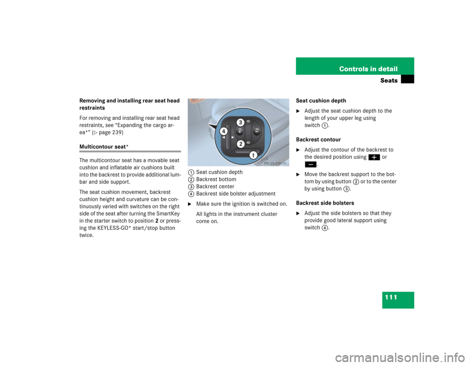
twice.1Seat cushion depth
2Backrest bottom
3Backrest center
4Backrest side bolster adjustment
�
Make sure the ignition is switched on.
All lights in the instrument cluster
come on.Seat cushion depth
�
Adjust the seat cushion depth to the
length of your upper leg using
switch1.
Backrest contour
�
Adjust the contour of the backrest to
the desired position using æ or
ç.
�
Move the backrest support to the bot-
tom by using button2 or to the center
by using button3.
Backrest side bolsters
�
Adjust the side bolsters so that they
provide good lateral support using
switch4.
Page 113 of 442
113 Controls in detailSeats
Massage function (PULSE)
The massage function can help prevent
muscle tension during long drives.�
Press button6.
The indicator lamp in button2 comes
on. The air cushions in the lumbar area
pulsate.
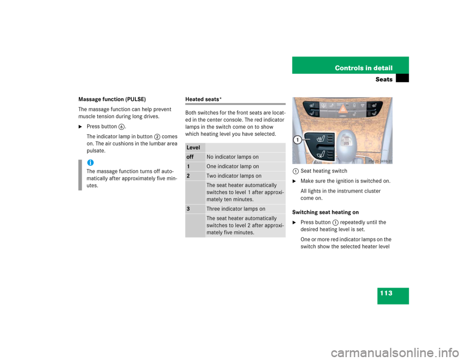
Heated seats*
Both switches for the front seats are locat-
ed in the center console. The red indicator
lamps in the switch come on to show
which heating level you have selected.
1Seat heating switch
�
Make sure the ignition is switched on.
All lights in the instrument cluster
come on.
Switching seat heating on
�
Press button1 repeatedly until the
desired heating level is set.
One or more red indicator lamps on the
switch show the selected heater level
iThe massage function turns off auto-
matically after approximately five min-
utes.
Leveloff
No indicator lamps on
1
One indicator lamp on
2
Two indicator lamps onThe seat heater automatically
switches to level 1 after approxi-
mately ten minutes.
3
Three indicator lamps onThe seat heater automatically
switches to level 2 after approxi-
mately five minutes.