Page 227 of 442

227 Controls in detail
Driving systems
Vehicle level control
Your vehicle automatically adjusts its ride
height to�
reduce fuel consumption
�
increase vehicle safety
The following vehicle chassis ride heights
can be selected:
�
Normal
�
RaisedThe vehicle chassis ride height is raised or
lowered according to the selected level
setting and to the vehicle speed:
�
At a speed above approximately above
68 mph (110 km / h) and the sporty
suspension style selected
(�page 226), ride height is reduced
automatically by up to approximately
0.6in (15mm).
�
With decreasing speed, the ride height
is again raised to the “Normal” level.Select the “Raised” level only when re-
quired by current driving conditions. Oth-
erwise
�
fuel consumption may increase
�
handling may be impaired
iThese height adjustments are so small
that you may not notice any change.
Warning!
G
To help avoid personal injury, keep hands
and feet away from wheel housing area, and
stay away from under the vehicle when low-
ering the vehicle chassis.
Page 228 of 442

228 Controls in detailDriving systemsThe following vehicle level settings can be
selected when the vehicle is stationary and
the engine is running:
The button is located in the lower section
of the center console.
1Vehicle level control button
2Indicator lamp
�
Briefly press button1 to change from
“Normal” level to “Raised” level. When
vehicle is at “Raised” level, pressing
the switch will return the vehicle to
“Normal” level.
Vehicle level when
stationary
Use for
Ride height increase
over normal
Automatic lowering
Indicator lamp (
�page 228)
Normal
Normal operation
None
Max. approx. 0.6 in
(15 mm)
Lamp off
Raised
Driving with snow
chains or very rough
road surface conditions
Approximately 0.8 in
(20 mm)
Max. approx. 1.4 in
(35 mm)
Lamp on
iAt a speed of approximately above
75 mph (120 km / h) or if the speed
amounts to between 50 mph
(80 km / h) and 75 mph (120 km / h)
for approximately five minutes, the set-
ting “Raised” is canceled. The message Level selec. canceled
appears in the
multifunction display.
If you do not drive in this speed range,
the “Raised” level remains stored even
if the SmartKey is removed from the
starter switch.
Page 229 of 442

The Parktronic system is an electronic aid
designed to assist the driver during park-
ing maneuvers. It visually and audibly")
229 Controls in detail
Driving systems
Parktronic system* (Parking assist)
The Parktronic system is an electronic aid
designed to assist the driver during park-
ing maneuvers. It visually and audibly indi-
cates the relative distance between the
vehicle and an obstacle.
The Parktronic system is automatically ac-
tivated when you switch on the ignition
and release the parking brake. The
Parktronic system deactivates at speeds
over 11 mph (18 km / h). At lower speeds
the Parktronic system turns on again.The Parktronic system monitors the sur-
roundings of your vehicle with six sensors
in the front bumper and four sensors in the
rear bumper.
1Sensors in the front bumperWarning!
G
The Parktronic system is a supplemental
system. It is not intended to, nor does it re-
place, the need for extreme care. The re-
sponsibility during parking and other critical
maneuvers always rests with the driver.
Special attention must be paid to objects
with smooth surfaces or low silhouettes
(e.g. trailer couplings, painted posts, or road
curbs). Such objects may not be detected by
the system and can damage the vehicle.
The operational function of the Parktronic
system can be affected by dirty sensors, es-
pecially at times of snow and ice. See
“Cleaning the Parktronic system sensors”
(�page 305).
Interference caused by other ultrasonic sig-
nals (e.g. working jackhammers or the air
brakes of trucks) can cause the system to
send erratic indications, and should be tak-
en into consideration.
Warning!
G
Make sure that no persons or animals are in
the area in which you are maneuvering. You
could otherwise injure them.
Page 230 of 442

230 Controls in detailDriving systemsRange of the sensors
To function properly, the sensors must be
free of dirt, ice, snow and slush. Clean the
sensors regularly, being careful not to
scratch or damage the sensors.Front sensors
Rear sensorsMinimum distance
If the system detects an obstacle in this
range, all the warning lamps come on and
you hear a warning signal. If the obstacle is
closer than the minimum distance, the ac-
tual distance might no longer be indicated
by the system.
Center
approx. 40 in (100 cm)
Corners
approx. 48 in (120 cm)
Center
approx. 48 in (120 cm)
Corners
approx. 32 in (80 cm)
!During parking maneuvers, pay special
attention to objects located above or
below the height of the sensors (e.g.
planters or trailer hitches). The
Parktronic system will not detect such
objects at close range and damage to
your vehicle or the object may result.
Ultrasonic signals from outside sourc-
es (e.g. truck air brakes or jackham-
mers) may impair the operation of the
Parktronic system.
Center
approx. 8 in (20 cm)
Corners
approx. 6 in (15 cm)
Page 231 of 442

231 Controls in detail
Driving systems
Warning indicators
Visual signals indicate to the driver the rel-
ative distance between the sensors and an
obstacle. The warning indicator for the
front area is located above the center air
vents in the dashboard. The warning indi-
cator for the rear area is integrated in the
rear trim.Front area warning indicator1Left side of the vehicle
2Right side of the vehicleEach warning indicator is divided into six
yellow and two red segments for either
side of the vehicle. The Parktronic system
is ready when the border around the indi-
cator is illuminated.
The position of the gear selector lever de-
termines which warning indicators will be
activated.
As your vehicle approaches an object, one
or more segments will come on, depending
on the distance. When the eighth segment
comes on, you have reached the minimum
distance.
�
Front area: An intermittent acoustic
warning will sound as the first red seg-
ment comes on and a constant acous-
tic warning lasting a maximum of
three seconds will sound for the sec-
ond red segment. The signal is can-
celed when the selector lever is placed
in positionP and the parking brake is
activated.
�
Rear area: An intermittent acoustic
warning will sound as the first red seg-
ment comes on and a constant acous-
tic warning lasting a maximum of
three seconds will sound for the sec-
ond red segment. The signal is can-
celed when the selector lever is placed
in position D orP and the parking
brake is activated.
Selector lever po-
sition
Warning indicator
D
Front area activated
R or N
Front and rear area
activated
P
Neither activated
Page 232 of 442

232 Controls in detailDriving systemsSwitching the Parktronic system
on / off
You can switch off the Parktronic system
manually.
The Parktronic system switch is located in
the lower section of the center console.
1Parktronic system on / off
2Indicator lampSwitching off the Parktronic system
�
Press button 1.
Indicator lamp 2 comes on.
Switching on the Parktronic system
�
Press button 1 again.
Indicator lamp 2 goes out.
Parktronic system malfunction
There is a malfunction in the Parktronic
system if the red segments of the
Parktronic system warning indicator come
on and a warning sounds. The Parktronic
system will switch itself off after
30 seconds and the indicator lamp on the
Parktronic system switch comes on.
�
Have the Parktronic system checked
by an authorized Mercedes-Benz Cen-
ter as soon as possible.If only the red segments of the Parktronic
system warning indicator come on and no
warning sounds, then the sensors of the
Parktronic system are dirty or malfunction-
ing. Malfunction may also be caused by in-
terference from other radio or ultrasonic
signals. The Parktronic system will switch
itself off after 20 seconds.
�
Clean Parktronic system sensors
(�page 305).
�
Switch on the ignition.
or
�
Check Parktronic system operation at
another location to rule out interfer-
ence from outside radio or ultrasonic
signals.
Page 233 of 442
233 Controls in detail
Loading
�Loading
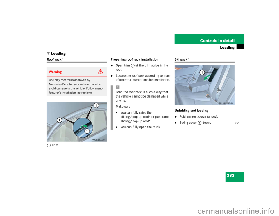
Roof rack*
1TrimPreparing roof rack installation
�
Open trim1 at the trim strips in the
roof.
�
Secure the roof rack according to man-
ufacturer’s instructions for installation.
Ski sack*
Unfolding and loading�
Fold armrest down (arrow).
�
Swing cover1 down.
Warning!
G
Use only roof racks approved by
Mercedes-Benz for your vehicle model to
avoid damage to the vehicle. Follow manu-
facturer’s installation instructions.
!Load the roof rack in such a way that
the vehicle cannot be damaged while
driving.
Make sure�
you can fully raise the
sliding / pop-up roof* or panorama
sliding / pop-up roof*
�
you can fully open the trunk
��
Page 237 of 442
237 Controls in detail
Loading
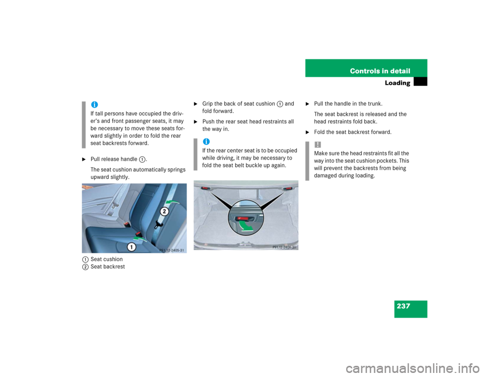
�
Pull release handle1.
The seat cushion automatically springs
upward slightly.
1Seat cushion
2Seat backrest
�
Grip the back of seat cushion1 and
fold forward.
�
Push the rear seat head restraints all
the way in.
�
Pull the handle in the trunk.
The seat backrest is released and the
head restraints fold back.
�
Fold the seat backrest forward.
iIf tall persons have occupied the driv-
er’s and front passenger seats, it may
be necessary to move these seats for-
ward slightly in order to fold the rear
seat backrests forward.
iI f t h e r e a r c e n t e r s e a t i s t o b e o c c u p i e d
while driving, it may be necessary to
fold the seat belt buckle up again.
!Make sure the head restraints fit all the
way into the seat cushion pockets. This
will prevent the backrests from being
damaged during loading.