Page 358 of 442
358 Practical hintsOpening / closing in an emergency
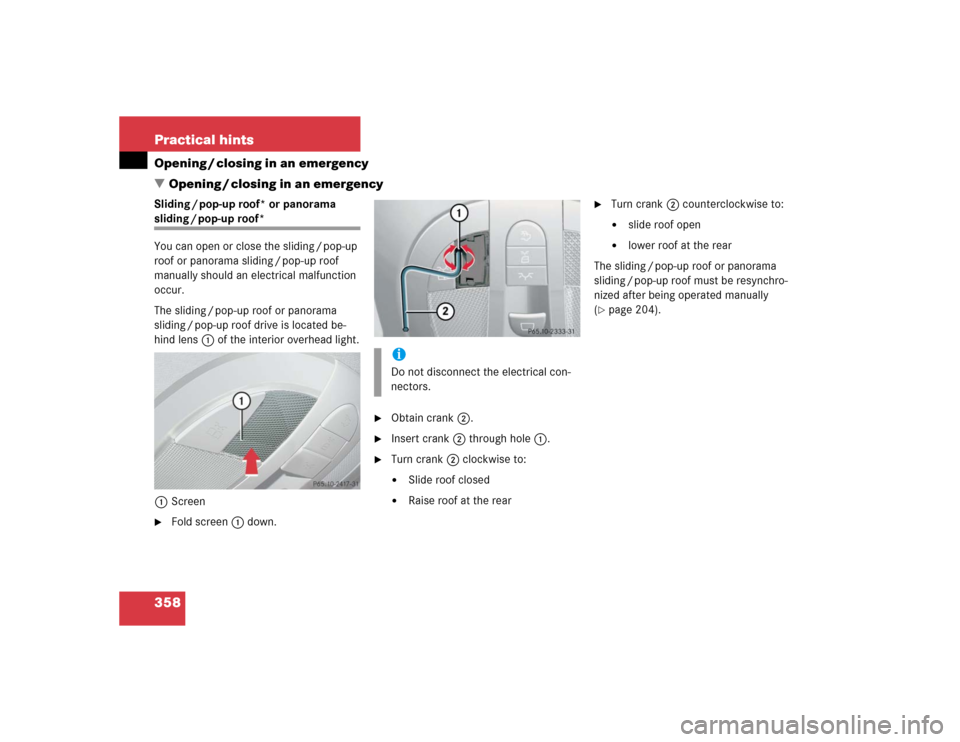
�Opening / closing in an emergencySliding / pop-up roof* or panorama sliding / pop-up roof*
You can open or close the sliding / pop-up
roof or panorama sliding / pop-up roof
manually should an electrical malfunction
occur.
The sliding / pop-up roof or panorama
sliding / pop-up roof drive is located be-
hind lens1 of the interior overhead light.
1Screen�
Fold screen1 down.
�
Obtain crank2.
�
Insert crank2 through hole1.
�
Turn crank2 clockwise to:�
Slide roof closed
�
Raise roof at the rear
�
Turn crank2 counterclockwise to:�
slide roof open
�
lower roof at the rear
The sliding / pop-up roof or panorama
sliding / pop-up roof must be resynchro-
nized after being operated manually
(
�page 204).
iDo not disconnect the electrical con-
nectors.
Page 361 of 442
361 Practical hints
Replacing bulbs
Replacing bulbs for front lamps
1Bulb socket for turn signal lamp
2High beam halogen bulb
3Bulb socket for parking and standing
lamp
4Cover for Bi-Xenon* (low beam and
high beam) or halogen (low beam)
headlampBi-Xenon* headlamps Low beam halogen bulb
�
Switch off the lights.
�
Open the hood (
�page 281).
�
Turn the locking mechanism counter-
clockwise and remove headlamp
cover4.
�
Pull electrical connector off.
�
Release the retaining springs and take
out the bulb.
�
Insert the new bulb in the socket so
that the base is in the recess on the
lower left.
�
Attach the retaining springs.
�
Insert connector into the bulb.
�
Align headlamp cover and click into
place.
Warning!
G
Do not remove the cover4 for the Bi-Xe-
non headlamp. Because of high voltage in
Xenon lamps, it is dangerous to replace the
bulb or repair the lamp and its components.
We recommend that you have such work
done by a qualified technician.
Page 362 of 442
.
�
Press the clamp and remove headlamp
cover.
�
Pull electrical connector off.
�
Turn th")
362 Practical hintsReplacing bulbsHigh beam halogen bulb �
Switch off the lights.
�
Open the hood (
�page 281).
�
Press the clamp and remove headlamp
cover.
�
Pull electrical connector off.
�
Turn the locking mechanism counter-
clockwise and take out the high beam
bulb2.
�
Insert the new bulb in the socket so
that the base is in the recess on the
lower left.
�
Attach the retaining springs.
�
Insert connector into the bulb.
�
Align headlamp cover and click into
place.Front turn signal lamp bulb
�
Switch off the lights.
�
Open the hood (
�page 281).
�
Twist bulb socket 1 counterclockwise
and pull out.
�
Push bulb into socket, turn counter-
clockwise and remove.
�
Insert new bulb in socket, push in and
twist clockwise.
�
Reinsert bulb socket in lamp and twist
clockwise.Parking and standing lamp bulb
�
Switch off the lights.
�
Open the hood (
�page 281).
�
Press the clamp and remove headlamp
cover.
�
Pull out the bulb socket3 with the
bulb.
�
Pull the bulb out of the bulb socket.
�
Insert a new bulb in the socket.
�
Reinstall the bulb socket.
�
Align headlamp cover and click into
place.
Page 363 of 442

363 Practical hints
Replacing bulbs
Side marker lamp bulb�
Switch off the lights.
�
Carefully slide lamp towards front.
�
Remove rear end first.
�
Twist bulb socket counterclockwise
and pull out.
�
Pull bulb out of the bulb socket.
�
Insert new bulb in socket.
�
Reinstall bulb socket, push in and twist
clockwise.
�
To reinstall lamp, set rear end in
bumper and let front end snap into
place.
Replacing bulbs for rear lamps
Tail lamp assemblies
The tail lamps are equipped with HiP bulbs.License plate lamp
1Screw
�
Switch off the lights.
�
Loosen both screws1 and remove
lamp.
�
Replace the tubular lamp and reinstall
lamp.
�
Retighten the screws.
!To prevent scratches, we recommend
that you have the sidemarker bulb re-
placed by an authorized
Mercedes-Benz Center.Warning!
G
The bulbs in the tail lamps cannot be re-
placed individually. The tail lamp bulbs are
under pressure and could explode during an
attempt to replace them.
If the tail lamps are malfunctioning, have
them exchanged at an authorized
Mercedes-Benz Center.
Page 374 of 442
")
374 Practical hintsFlat tireIn the case of a flat tire, you may tempo-
rarily use the Minispare wheel when ob-
serving the following restrictions:�
Do not exceed a vehicle speed of
50 mph (80 km / h).
�
Drive to the nearest tire repair facility
to have the flat tire repaired or re-
placed as appropriate.
�
Do not operate vehicle with more than
one spare wheel mounted.Lowering the vehicle
�
Lower vehicle by turning crank coun-
terclockwise until vehicle is resting ful-
ly on its own weight.
�
Remove the jack.
1-5 Wheel bolts
�
Tighten the five wheel bolts evenly, fol-
lowing the diagonal sequence illustrat-
ed (1 to 5), until all bolts are tight.
Observe a tightening torque of 96 lb-ft
(130 Nm).
�
Before storing the jack in the trunk, it
should be fully collapsed.
Warning!
G
The dimensions of the Minispare wheel are
different from those of the road wheels. As
a result, the vehicle handling characteristics
change when driving with a Minispare wheel
mounted.
The spare wheel should only be used tempo-
rarily, and replaced with a regular road
wheel as quickly as possible.
Warning!
G
Have the tightening torque checked after
changing a wheel. The wheels could come
loose if they are not tightened to a torque of
96 lb-ft (130 Nm).iWrap the damaged wheel in the protec-
tive film that comes with the spare
wheel and put the wheel in the trunk.
You can also place the damaged wheel
down into the spare wheel well. In this
case, you must stow the holder from
the spare wheel well in the trunk.
Do not activate the tire inflation pres-
sure monitor until the depressurized
tire is no longer in the vehicle.
Page 377 of 442
.
�
Disconnect battery negative lead1.
�
Remove cover2 from the positive ter-
minal.
�
Disconnect the battery positive lead.
Removing")
377 Practical hints
Batteries
�
Remove the luggage box (
�page 351).
�
Disconnect battery negative lead1.
�
Remove cover2 from the positive ter-
minal.
�
Disconnect the battery positive lead.
Removing the battery�
Remove the screw-nuts securing the
battery.
�
Remove the battery bracket.
�
Take out the battery.
Charging and reinstalling the battery
�
Charge battery in accordance with the
instructions of the battery charger
manufacturer.
�
Reinstall the charged battery. Follow
the previously described steps in re-
verse order.
Reconnecting the battery�
Turn off all electrical consumers.
�
Connect the positive lead and fasten its
cover.
�
Connect the negative lead.
�
Install the luggage box (
�page 351).Batteries contain materials that can harm
the environment if disposed of improperly.
Large 12 volt storage batteries contain
lead. Recycling of batteries is the preferred
method of disposal. Many states require
sellers of batteries to accept old batteries
for recycling.
Warning!
G
Never charge a battery while still installed in
the vehicle. Gases may escape during charg-
ing and cause explosions that may result in
paint damage, corrosion or personal injury.
!Never invert the terminal connections!!The battery, its filler caps and the vent
tube must always be securely installed
when the vehicle is in operation.
iThe following procedures must be car-
ried out following any interruption of
battery power (e.g. due to reconnec-
tion):�
Set the clock (
�page 143)
(see COMAND operator’s manual).
�
Resynchronize the side windows
(�page 200).
�
Resynchronize the sliding / pop-up
roof* (
�page 204) or the panora-
ma sliding / pop-up roof*
(
�page 209).
Page 385 of 442

385 Practical hintsFuses
�Fuses
Fuse box in passenger compartment
1CoverOpening
�
Pull cover1 open with a screwdriver
or similar tool.
�
Remove cover1 rearward.
Closing
�
Attach cover1 in the front.
�
Fold cover1 in until it engages.
2Cover
3Catches
�
Turn catches3 anti-clockwise and re-
move cover2.Fuse chart
The fuse chart is found in the fuse box in
the passenger compartment. The amper-
ages of the fuses are also given there.
Spare fuses
Spare fuses are found in the vehicle tool kit
in the trunk.
Fuse extractor
The fuse extractor is found in the vehicle
tool kit in the trunk.
iOnly install fuses that have been tested
and approved by Mercedes-Benz and
that have the specified amperage rat-
ing.
Never attempt to repair or bridge a
blown fuse. Have the cause determined
and remedied by an authorized
Mercedes-Benz Center.
iOnly install fuses that have been tested
and approved by Mercedes-Benz and
that have the specified amperage rat-
ing.
Never attempt to repair or bridge a
blown fuse. Have the cause determined
and remedied by an authorized
Mercedes-Benz Center.
Page 420 of 442
 411
Calling up
Distronic* settings 136
Range (distance to empty) 154
Service indicator 298
CAN system 411
Cargo tie-down rings 241
CD player
Operating 135
C")
420 IndexC
CAC (Customer Assistance Center) 411
Calling up
Distronic* settings 136
Range (distance to empty) 154
Service indicator 298
CAN system 411
Cargo tie-down rings 241
CD player
Operating 135
Center console
Lower part 26
PASSENGER AIRBAG OFF indicator
lamp 317
Upper part 25
Centigrade
Setting temperature units 141
Central locking
Automatic 106
From inside 107
Switch 107
Switching on/off (control
system) 149
Unlocking from inside 107Central locking switch 107
Changing
Batteries (SmartKey with
KEYLESS-GO*) 355, 356
Batteries (SmartKey) 355, 356
Smartkey setting 150
Vehicle level 228
Charcoal filter 192
Activating 192
Deactivating 193
Charging
Vehicle batteries 377
CHECK ENGINE malfunction indicator
lamp 313
Checking
Coolant level 285
Oil level 279, 282
Tire inflation pressure 279
Vehicle lighting 279
Child safety 65
Airbags 58
Infant and child restraint systems 62,
65
LATCH child seat anchors 71Child safety switch see Blocking of rear
window operation 72
Cigarette lighter 247
Cleaning
Headlamps 170
Light alloy wheels 305
Parktronic* system sensor 305
Windshield 49
Wood trims 308
Climate control 174
Adjusting 178
Defrosting 179
Setting the temperature 178
Clock 144
Closing
Glove box 242
Panorama sliding/pop-up roof 206
Panorama sliding/pop-up roof with
KEYLESS-GO* 209
Panorama sliding/pop-up roof* with
KEYLESS-GO* 200
Roller sunblinds 205
Side windows 198