Page 350 of 440
350 Practical hintsReplacing bulbs
�Replacing bulbsSafe vehicle operation depends on proper
exterior lighting and signaling. It is there-
fore essential that all bulbs and lamp as-
semblies are in good working order at all
times.
Correct headlamp adjustment is extremely
important. Have headlamps checked and
readjusted at regular intervals and when a
bulb has been replaced. See your autho-
rized Mercedes-Benz Center for headlamp
adjustment.
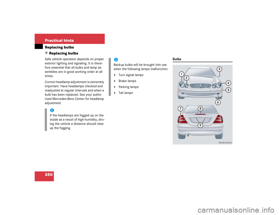
Bulbs
iIf the headlamps are fogged up on the
inside as a result of high humidity, driv-
ing the vehicle a distance should clear
up the fogging.
iBackup bulbs will be brought into use
when the following lamps malfunction:�
Turn signal lamps
�
Brake lamps
�
Parking lamps
�
Tail lamps
Page 351 of 440
351 Practical hints
Replacing bulbs
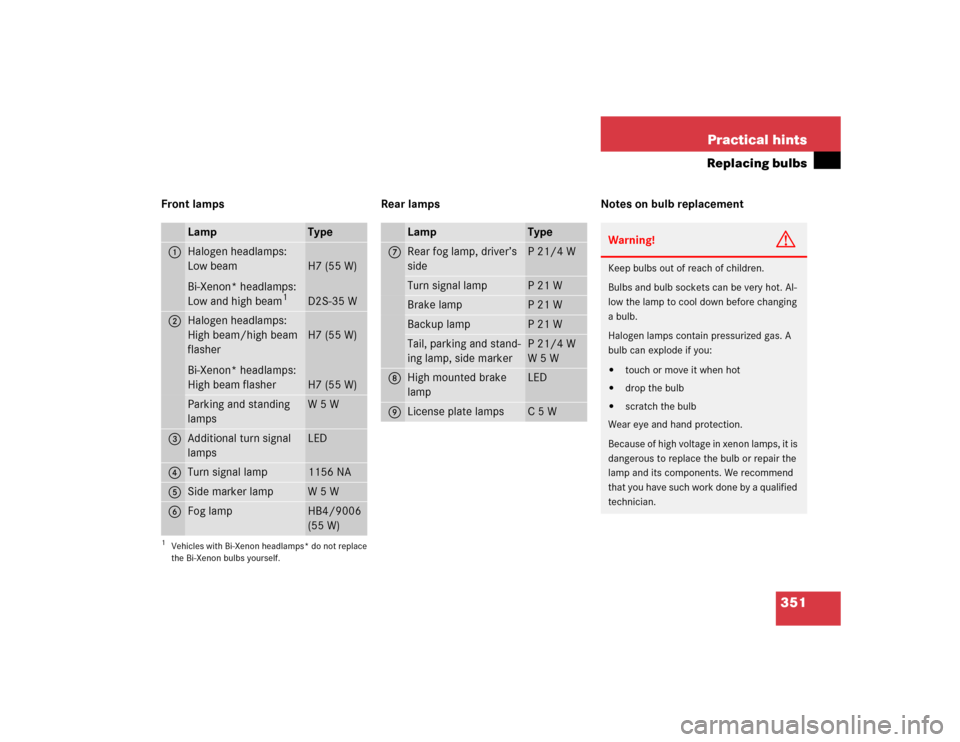
Front lamps Rear lamps Notes on bulb replacement
Lamp
Type
1
Halogen headlamps:
Low beam
Bi-Xenon* headlamps:
Low and high beam
1
1Vehicles with Bi-Xenon headlamps* do not replace
the Bi-Xenon bulbs yourself.
H7 (55 W)
D2S-35 W
2
Halogen headlamps:
High beam/high beam
flasher
Bi-Xenon* headlamps:
High beam flasher
H7 (55 W)
H7 (55 W)
Parking and standing
lamps
W 5 W
3
Additional turn signal
lamps
LED
4
Turn signal lamp
1156 NA
5
Side marker lamp
W 5 W
6
Fog lamp
HB4/9006
(55 W)
Lamp
Type
7
Rear fog lamp, driver’s
side
P 21/4 W
Turn signal lamp
P 21 W
Brake lamp
P 21 W
Backup lamp
P 21 W
Tail, parking and stand-
ing lamp, side marker
P 21/4 W
W 5 W
8
High mounted brake
lamp
LED
9
License plate lamps
C 5 W
Warning!
G
Keep bulbs out of reach of children.
Bulbs and bulb sockets can be very hot. Al-
low the lamp to cool down before changing
a bulb.
Halogen lamps contain pressurized gas. A
bulb can explode if you:�
touch or move it when hot
�
drop the bulb
�
scratch the bulb
Wear eye and hand protection.
Because of high voltage in xenon lamps, it is
dangerous to replace the bulb or repair the
lamp and its components. We recommend
that you have such work done by a qualified
technician.
Page 352 of 440
352 Practical hintsReplacing bulbs�
Only use 12 volt bulbs of the same type
and with the specified watt rating.
�
Switch lights off before changing a bulb
to prevent short circuits.
�
Always use a clean lint-free cloth when
handling bulbs.
�
Your hands should be dry and free of oil
and grease.
�
If the newly installed bulb does not
come on, visit an authorized
Mercedes-Benz Center.
�
Have the LEDs and bulbs for the follow-
ing lamps replaced by an authorized
Mercedes-Benz Center.�
Additional turn signal lamps in the
exterior rear view mirrors
�
High mounted brake lamp
�
Bi-Xenon* lamps
�
Front fog lamps
Replacing bulbs for front lamps
Front lamps halogen-type
1Housing cover for low beam lamp
2Housing cover for high beam lamp3Bulb socket for turn signal lamp
4Low beam bulb
5High beam bulb
6Parking and standing lamp
Page 358 of 440
358 Practical hintsFlat tire
�Flat tirePreparing the vehicle�
Park the vehicle as far as possible from
moving traffic on a hard surface.
�
Turn on the hazard warning flashers.
�
Engage the steering wheel lock in the
straight ahead position and set the
parking brake.
�
Move the gear selector lever toP.
�
Have any passenger exit the vehicle at
a safe distance from the roadway.
Mounting the Minispare wheelIn case of a flat tire, you may temporarily
use the spare wheel when observing the
following restrictions:
�
Do not exceed a vehicle speed of
50 mph (80 km/h).
�
Drive to the nearest tire repair facility
to have the flat tire repaired or re-
placed as appropriate.
�
Do not operate the vehicle with more
than one spare wheel mounted.
Prepare the vehicle as described on
(
�page 358).
�
Take the wheel wrench and the jack
out of the trunk (
�page 337).
�
Take the Minispare wheel and wheel
bolts out of the trunk (
�page 337).
Warning!
G
The dimensions of the Minispare wheel are
different from those of the road wheels. As
a result, the vehicle handling characteristics
change when driving with a Minispare wheel
mounted.
The spare wheel should only be used tempo-
rarily, and should be replaced with a regular
road wheel as quickly as possible.
Page 359 of 440
359 Practical hints
Flat tire
Lifting the vehicle�
Prevent the vehicle from rolling away
by blocking wheels with wheel chocks
(not included) or other sizable objects.
When changing wheel on a level surface:
�
Place one chock in front of and one be-
hind the wheel that is diagonally oppo-
site to the wheel being changed.
When changing wheel on a hill:
�
Place chocks on the downhill side
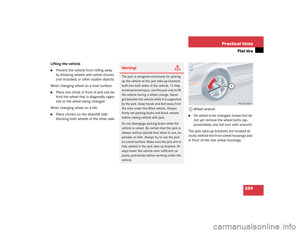
blocking both wheels of the other axle.1Wheel wrench
�
On wheel to be changed, loosen but do
not yet remove the wheel bolts (ap-
proximately one full turn with wrench).
The jack take-up brackets are located di-
rectly behind the front wheel housings and
in front of the rear wheel housings.
Warning!
G
The jack is designed exclusively for jacking
up the vehicle at the jack take-up brackets
built into both sides of the vehicle. To help
avoid personal injury, use the jack only to lift
the vehicle during a wheel change. Never
get beneath the vehicle while it is supported
by the jack. Keep hands and feet away from
the area under the lifted vehicle. Always
firmly set parking brake and block wheels
before raising vehicle with jack.
Do not disengage parking brake while the
vehicle is raised. Be certain that the jack is
always vertical (plumb line) when in use, es-
pecially on hills. Always try to use the jack
on a level surface. Make sure the jack arm is
fully seated in the jack take-up bracket. Al-
ways lower the vehicle onto sufficient ca-
pacity jackstands before working under the
vehicle.
Page 364 of 440
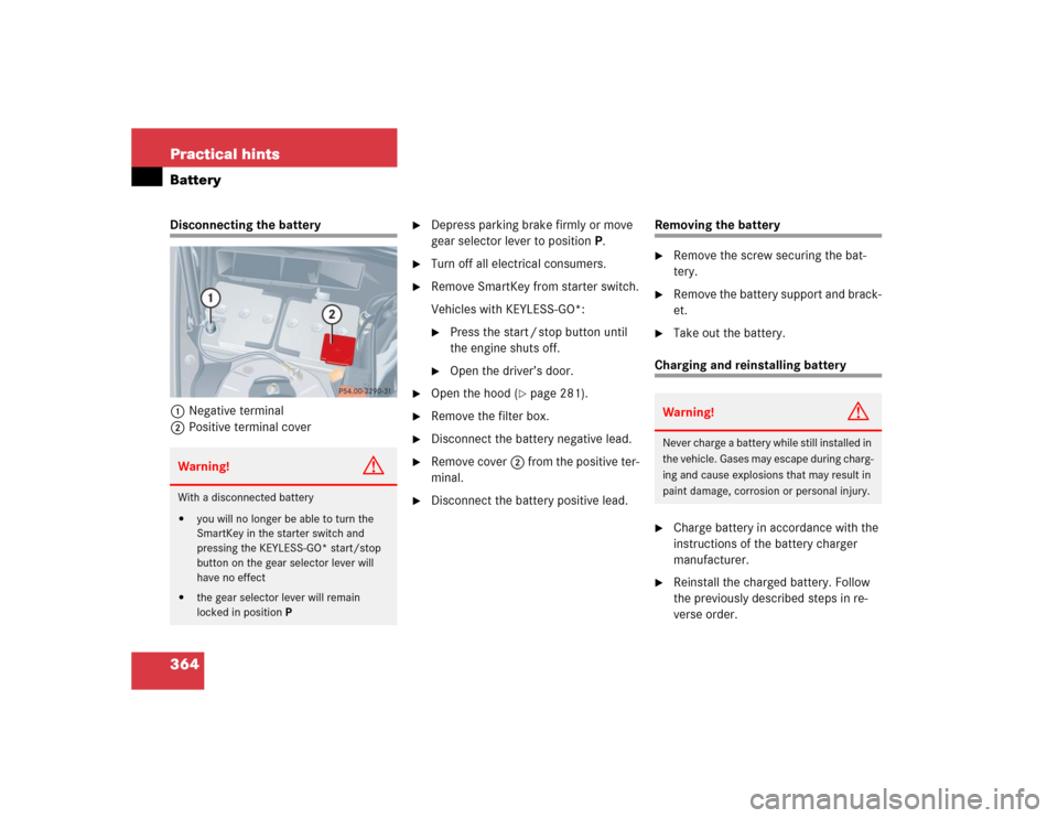
364 Practical hintsBatteryDisconnecting the battery
1Negative terminal
2Positive terminal cover
�
Depress parking brake firmly or move
gear selector lever to positionP.
�
Turn off all electrical consumers.
�
Remove SmartKey from starter switch.
Vehicles with KEYLESS-GO*:�
Press the start / stop button until
the engine shuts off.
�
Open the driver’s door.
�
Open the hood (
�page 281).
�
Remove the filter box.
�
Disconnect the battery negative lead.
�
Remove cover2 from the positive ter-
minal.
�
Disconnect the battery positive lead.
Removing the battery�
Remove the screw securing the bat-
tery.
�
Remove the battery support and brack-
et.
�
Take out the battery.
Charging and reinstalling battery�
Charge battery in accordance with the
instructions of the battery charger
manufacturer.
�
Reinstall the charged battery. Follow
the previously described steps in re-
verse order.
Warning!
G
With a disconnected battery�
you will no longer be able to turn the
SmartKey in the starter switch and
pressing the KEYLESS-GO* start/stop
button on the gear selector lever will
have no effect
�
the gear selector lever will remain
locked in positionP
Warning!
G
Never charge a battery while still installed in
the vehicle. Gases may escape during charg-
ing and cause explosions that may result in
paint damage, corrosion or personal injury.
Page 367 of 440
367 Practical hints
Jump starting
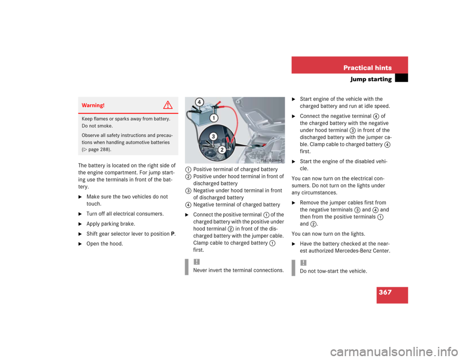
The battery is located on the right side of
the engine compartment. For jump start-
ing use the terminals in front of the bat-
tery.�
Make sure the two vehicles do not
touch.
�
Turn off all electrical consumers.
�
Apply parking brake.
�
Shift gear selector lever to positionP.
�
Open the hood.1Positive terminal of charged battery
2Positive under hood terminal in front of
discharged battery
3Negative under hood terminal in front
of discharged battery
4Negative terminal of charged battery
�
Connect the positive terminal1 of the
charged battery with the positive under
hood terminal 2 in front of the dis-
charged battery with the jumper cable.
Clamp cable to charged battery1
first.
�
Start engine of the vehicle with the
charged battery and run at idle speed.
�
Connect the negative terminal4 of
the charged battery with the negative
under hood terminal 3 in front of the
discharged battery with the jumper ca-
ble. Clamp cable to charged battery4
first.
�
Start the engine of the disabled vehi-
cle.
You can now turn on the electrical con-
sumers. Do not turn on the lights under
any circumstances.
�
Remove the jumper cables first from
the negative terminals3 and4 and
then from the positive terminals1
and2.
You can now turn on the lights.
�
Have the battery checked at the near-
est authorized Mercedes-Benz Center.
Warning!
G
Keep flames or sparks away from battery.
Do not smoke.
Observe all safety instructions and precau-
tions when handling automotive batteries
(�page 288).
!Never invert the terminal connections.
!Do not tow-start the vehicle.
Page 406 of 440

406 IndexBattery, vehicle 288, 363
Charging 364
Disconnecting 364
Messages in display 320
Reconnecting 365
Reinstalling 364
Removing 364
Bi-Xenon headlamps* 397
Block heater* 295
Blocking
Rear window operation 74
Bolts
For Minispare wheel 342
Brake assist system (BAS) 397
Brake fluid 390
Message in display 321
Brake lamp bulbs 351
Brake lamp, high mounted 351
Brake pads
Message in display 321
Brakes 268
Warning lamp 307
Break-in period 266Bulbs, replacing 350
Additional turn signals 351
Backup lamps 351
Brake lamps 351
Fog lamps 351
Front lamps 351
High beam (Bi-Xenon*) 351
High beam (Halogen) 351
High beam flasher (Bi-Xenon*) 351
High beam flasher (Halogen) 351
High mounted brake lamp 351
License plate lamps 351, 356
Low beam (Bi-Xenon*) 351
Low beam (Halogen) 351
Parking lamps 351, 353, 355
Rear fog lamp 351
Rear fog lamps 356
Side marker lamps 351, 355
Standing lamps 351, 353, 355
Tail lamp assemblies 351, 356
Turn signal lamps 351
Button
Audio system 186C
CAC (Customer Assistance Center) 398
Calling up
Distronic* settings 137
Range (distance to empty) 153
Service indicator 297
CAN system 398
Canceling
Cruise control 219
Capacities
Fuels, coolants, lubricants, etc. 388
Cargo tie-down rings 243
Cassette operation
Playing cassettes 196
Cassette player
Operating 136
Catalytic converter 275
CD changer* 199
CD operation 199
CD player
Operating 136