Page 324 of 400
.
�
Remove the filter box (
�page 323).")
324 Practical hintsBattery1Negative terminal
2Positive terminal cover
Disconnecting the battery�
Turn off all electrical consumers.
�
Open the hood (
�page 252).
�
Remove the filter box (
�page 323).
�
Disconnect battery negative lead1.
�
Remove cover2 from positive
terminal.
�
Disconnect the battery positive lead.
Removing the battery�
Remove the screw-nuts securing the
battery.
�
Remove the battery bracket.
�
Take out the battery.
Charging and reinstalling the battery�
Charge battery in accordance with the
instructions of the battery charger
manufacturer.
�
Reinstall the charged battery. Follow
the previously described steps in
reverse order.
Warning!
G
With a disconnected battery�
you will no longer be able to turn the
SmartKey in the starter switch
�
the gear selector lever will remain
locked in positionP
Warning!
G
Never charge a battery while still installed in
the vehicle. Gases may escape during charg-
ing and cause explosions that may result in
paint damage, corrosion or personal injury.
Page 325 of 400
325 Practical hints
Battery
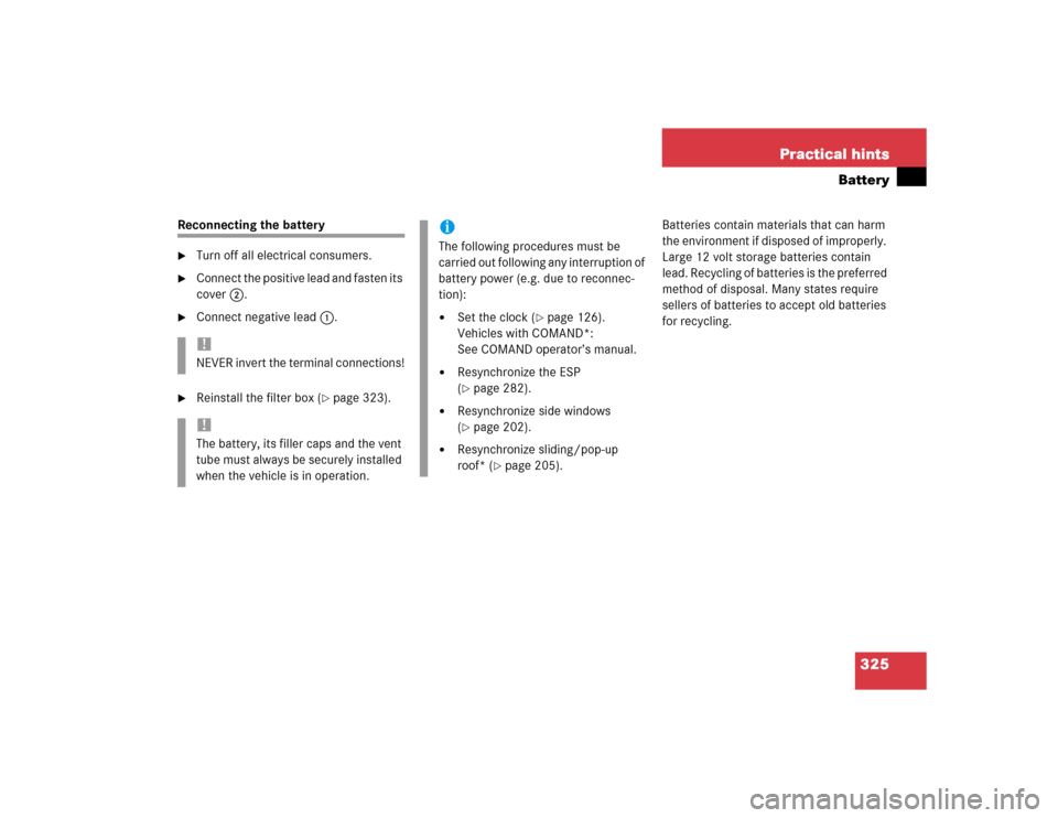
Reconnecting the battery�
Turn off all electrical consumers.
�
Connect the positive lead and fasten its
cover2.
�
Connect negative lead1.
�
Reinstall the filter box (
�page 323).Batteries contain materials that can harm
the environment if disposed of improperly.
Large 12 volt storage batteries contain
lead. Recycling of batteries is the preferred
method of disposal. Many states require
sellers of batteries to accept old batteries
for recycling.
!NEVER invert the terminal connections!!The battery, its filler caps and the vent
tube must always be securely installed
when the vehicle is in operation.
iThe following procedures must be
carried out following any interruption of
battery power (e.g. due to reconnec-
tion):�
Set the clock (
�page 126).
Vehicles with COMAND*:
See COMAND operator’s manual.
�
Resynchronize the ESP
(�page 282).
�
Resynchronize side windows
(�page 202).
�
Resynchronize sliding/pop-up
roof* (
�page 205).
Page 326 of 400

326 Practical hintsJump starting
�Jump starting
If the battery is discharged, the engine can
be started with jumper cables and the
battery of another vehicle. Observe the
following:�
Jump starting should only be performed
when the engine and catalytic con-
verter are cold.
�
Do not start the engine if the battery is
frozen. Let the battery thaw out first.
�
Only jump start from batteries with the
same voltage rating (12 V). Jump
starting with a more powerful battery
could damage the vehicle’s electrical
system, which will not be covered by
the Mercedes-Benz Limited Warranty.
�
Only use jumper cables with sufficient
cross-section and insulated terminal
clamps.
�
Always make sure the jumper cables
are not on or near pulleys, fans, or oth-
er parts that move when an engine is
started or running.
Warning!
G
Failure to follow these directions will cause
damage to the electronic components, and
can lead to a battery explosion and severe
injury or death.
Never lean over batteries while connecting
or jump starting, you might get injured.
Battery fluid contains sulfuric acid. Do not
allow this fluid to come in contact with eyes,
skin or clothing. In case it does, immediately
flush affected area with water, and seek
medical help if necessary.
A battery will also produce hydrogen gas,
which is flammable and very explosive. Keep
flames or sparks away from battery, avoid
improper connection of jumper cables,
smoking, etc.
Attempting to jump start a frozen battery
can result in it exploding, causing personal
injury.
Read all instructions before proceeding.
!Jump starting may only be performed
on the battery installed in the engine
compartment.
Avoid repeated and lengthy starting
attempts.
Do not attempt to start the engine
using a battery quick charge unit.
If engine does not run after several
unsuccessful starting attempts, have it
checked at the nearest authorized
Mercedes-Benz Center.
Excessive unburned fuel generated by
repeated failed starting attempts may
damage the catalytic converter and
may present a fire risk.
Make sure the jumper cables do not
have loose or missing insulation.
Make sure the cable clamps do not
touch any other metal part while the
other end is still attached to a battery.
Page 327 of 400

327 Practical hints
Jump starting
The battery is located in the engine
compartment on the right hand side. The
terminals for jump starting are located in
front of the battery.�
Make sure the two vehicles do not
touch.
�
Turn off all electrical consumers.
�
Apply parking brake.
�
Shift gear selector lever to positionP
(manual transmission to Neutral).1Positive terminal of charged battery
2Positive under hood terminal in front of
discharged battery
3Negative terminal of charged battery
4Negative under hood terminal in front
of discharged battery
�
Connect positive terminal1 of the
charged battery with positive under
hood terminal2 in front of the
discharged battery with the jumper
cables. Clamp cable to charged
battery1 first.
�
Start engine of the vehicle with the
charged battery and run at idle speed.
�
Connect negative terminal3 of the
charged battery with negative under
hood terminal4 of the discharged
battery with the jumper cables. Clamp
cable to charged battery3 first.
�
Start the engine of the disabled
vehicle.
You can now again turn on the electrical
consumers. Do not turn on the lights under
any circumstances.
�
Remove the jumper cables first from
negative terminals3 and4 and then
from positive terminals1 and2.
You can now turn on the lights.
�
Have the battery checked at the near-
est authorized Mercedes-Benz Center.
Warning!
G
Keep flames or sparks away from battery.
Do not smoke.
Observe all safety instructions and precau-
tions when handling automotive batteries
(�page 258).
!Vehicles with automatic transmission
and/or 4MATIC:
Do not tow-start the vehicle.
Page 330 of 400

330 Practical hintsTowing the vehicleWarning!
G
With the engine not running, there is no
power assistance for the brake and steering
systems. In this case, it is important to keep
in mind that a considerably higher degree of
effort is necessary to brake and steer the ve-
hicle. Adapt your driving accordingly.
!When towing the vehicle with all wheels
on the ground, please note the
following:
With the automatic central locking
activated and the SmartKey in starter
switch position2, the vehicle doors
lock if the left front wheel as well as the
right rear wheel are turning at vehicle
speeds of approx. 9 mph (15 km/h) or
more.
Switch off the tow-away alarm
(�page 79).
To prevent the vehicle doors from
locking, deactivate the automatic
central locking (
�page 133).
Towing of the vehicle should only be
done using the properly installed
towing eye bolt. Never attach tow
cable, tow rope or tow rod to vehicle
chassis, frame or suspension parts.
iIf the battery is disconnected or
discharged�
the SmartKey will not turn in the
starter switch. See notes on the
battery (
�page 323) or on jump
starting (�page 326).
�
the gear selector lever will remain
locked in positionP. See notes on
manually unlocking transmission
gear selector lever (
�page 308).
Page 346 of 400
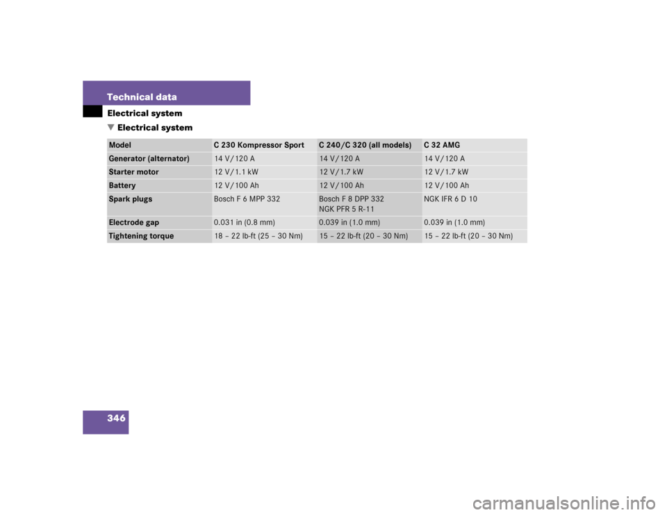
346 Technical dataElectrical system
�Electrical systemModel
C230KompressorSport
C 240/C 320 (all models)
C32AMG
Generator (alternator)
14 V/120 A
14 V/120 A
14 V/120 A
Starter motor
12 V/1.1 kW
12 V/1.7 kW
12 V/1.7 kW
Battery
12 V/100 Ah
12 V/100 Ah
12 V/100 Ah
Spark plugs
Bosch F 6 MPP 332
Bosch F 8 DPP 332
NGK PFR 5 R-11
NGK IFR 6 D 10
Electrode gap
0.031 in (0.8 mm)
0.039 in (1.0 mm)
0.039 in (1.0 mm)
Tightening torque
18–22lb-ft (25–30Nm)
15–22lb-ft (20–30Nm)
15 – 22 lb-ft (20 – 30 Nm)
Page 365 of 400

The Tele Aid system consists of three
types of response: automatic and
manual emergency, roadside assis-
tance an")
365 Technical terms
Tele Aid* System
(T
elematic A
larm I
dentification on
D
emand)
The Tele Aid system consists of three
types of response: automatic and
manual emergency, roadside assis-
tance and information. Tele Aid is
initially activated by completing a
subscriber agreement and placing an
acquaintance call.
The Tele Aid system is operational
provided that the vehicle’s battery is
charged, properly connected, not
damaged and cellular and GPS
coverage is available.Telematics*
A combination of the terms “tele-
communications” and “informatics”.
Tightening torque
Force times lever arm (e.g. a lug
wrench) with which threaded fasteners
such as wheel bolts are tightened.
Tire speed rating
Part of tire designation; indicates the
speed range for which a tire is
approved.Traction
Force exerted by the vehicle on the
road via the tires.
VIN
(V
ehicle I
dentification N
umber)
The number set by the manufacturer
and placed on the body to uniquely
identify each vehicle produced.
Voice control system*
Voice control system for car phones,
portable cell phones and audio
systems (radio, CD, etc.).
Page 370 of 400

370 IndexAutomatic climate control* 162
Activating 163
Adjusting air distribution 166
Adjusting air volume 166
Air recirculation mode 167
Deactivating 163
Defrosting 167
Rear window defroster 153
Residual heat utilization 171
Residual ventilation 171
Setting the temperature 165
Automatic headlamp mode 103
Automatic lighting control
Activating 107
Deactivating 107
Automatic locking when driving 90
Automatic transmission fluid see ATF
Automatic transmission* 142
Accelerator position 147
Comfort program mode 146
Emergency operation
(Limp Home Mode) 147
Fluid level 256Gear ranges 144
Gear selector lever 44
Gear selector lever position 142, 145
Gear shifting malfunctions 147
Kickdown 147
Manual shifting 143
One-touch gearshifting 143
Program mode selector switch 146
Starting with 44
Transmission fluid 256
Auxiliary fuse box 334
B
BabySmart
TM
Airbag deactivation system 66, 361
Compatible child seats 66, 361
Self-test 66
Backrest
Folding forward 213
Folding rearward 213
Backrest contour
Adjusting 97Backrest side bolsters
Adjusting 97
Backrest tilt
Manual seat 33
Power seat* 35
Backup lamps 311, 315
Bulbs 310
BAS 73, 361
Messages in display 281
Batteries, SmartKey
Changing 307
Check lamp 83
Checking 84
Battery discharged
Jump starting 326
Battery, vehicle 258, 323
Charging 324
Disconnecting 324
Messages in display 285
Reconnecting 325
Reinstalling 324
Removing 324