Page 73 of 376

�
BAS (B
rak")
73
Safety and Security
Driving safety systems
� Driving safety systems
In this section you will find informations on
the following driving safety systems:�
ABS (A
ntilock B
rake S
ystem)
�
BAS (B
rake A
ssist S
ystem)
�
ESP (E
lectronic S
tability P
rogram)
ABS
The Antilock Brake System (ABS) regulates
the brake pressure so that the wheels do
not lock during braking. This allows you to
maintain the ability to steer your vehicle.
The ABS is functional above a speed of ap-
proximately 5 mph (8 km/h) independent
of road surface conditions.
On slippery road surfaces, the ABS will re-
spond even with light brake pressure.
The - indicator lamp in the instrument
cluster (
�page 22) comes on when you
turn the SmartKey in the starter switch to
position 2. It goes out when the engine is
running. Braking
At the instant one of the wheels is about to
lock up, a slight pulsation can be felt in the
brake pedal, indicating that the ABS is in
the regulating mode.
�
Keep firm and steady pressure on the
brake pedal while experiencing the pul-
sation.
Continuous, steady brake pedal pressure
yields the advantages provided by the ABS,
namely braking power and the ability to
steer the vehicle.
The pulsating brake pedal can be an indica-
tion of hazardous road conditions and
functions as a reminder to take extra care
while driving.
iIn winter operation, the maximum ef-
fectiveness of the ABS, ESP is only
achieved with winter tires (M + S tires),
or snow chains as required.Warning!
G
The following factors increase the risk of ac-
cidents:�
Excessive speed, especially in turns
�
Wet and slippery road surfaces
�
Following another vehicle too closely
The ABS, BAS, ESP cannot reduce this risk.
Always adjust your driving style to the pre-
vailing road and weather conditions.
Warning!
G
Do not pump the brake pedal. Use firm,
steady brake pedal pressure instead. Pump-
ing the brake pedal defeats the purpose of
the ABS and significantly reduces braking
effectiveness.
Page 93 of 376
.
�
Pull head restraint to its h")
93
Controls in detail
Seats
Removing and installing rear seat head
restraints
1Release button
Removing rear seat head restraints
�
Fold back head restraint (
�page 92).
�
Pull head restraint to its highest posi-
tion.
�
Press release button 1 and pull out
head restraint.
Installing rear seat head restraints
�
Insert head restraint and push it down
until it engages.
�
Press release button 1 and adjust
head restraint to desired position.
Heated seats*
Both switches for the front seats are locat-
ed in the center console.
1 Normal heating
2 Rapid heating�
Make sure the ignition is switched on.
All the lights in the instrument cluster
come on.
Warning!
G
For your protection, drive only with properly
positioned head restraints.
Adjust head restraint so that the head re-
straint supports the back of the head at eye
level. This will reduce the potential for injury
to the head and neck in the event of an ac-
cident or similar situation.
Do not drive the vehicle without the seat
head restraints. Head restraints are intend-
ed to help reduce injuries during an acci-
dent.
Do not interchange head restraints from
front and rear seat.
Page 99 of 376

99
Controls in detail
Lighting
Manual headlamp mode
The low beam headlamps and parking
lamps can be switched on and off with the
exterior lamp switch.
Automatic headlamp mode
The parking lamps, low beam headlamps
and license plate lamps switch on and off
automatically depending on the brightness
of the ambient light.�
Turn the exterior lamp switch to
U.
iIf you remove the SmartKey and open
the driver’s door while the parking
lamps or low beam headlamps are
switched on, �
a warning sounds
�
$ appears in the multifunction
display
�
the message
TURN OFF LIGHTS!
appears in the multifunction display
iWith the daytime running lamp mode
activated and the engine running, the
low beam headlamps cannot be
switched off manually.
Warning!
G
If the exterior lamp switch is set to U,�
the headlamps may switch off unexpect-
edly when the system senses bright am-
bient light, for example light from
oncoming traffic.
�
the headlamps will not be automatically
switched on under foggy conditions.
To minimize risk to you and to others, acti-
vate headlamps by turning exterior lamp
switch to
B
when driving or when traffic
and / or ambient lighting conditions require
you to do so.
In low ambient lighting conditions, only
switch from position
U
to
B
with the
vehicle at a standstill. Switching from U
to
B
will briefly switch off the head-
lamps. Doing so while driving in low ambient
lighting conditions may result in an acci-
dent.
The automatic headlamp feature is only an
aid to the driver. The driver is responsible for
the operation of the vehicle's lights at all
times.
Page 101 of 376
101
Controls in detail
Lighting
Switching on fog lamps
Switching on front fog lamps
�
Make sure the low beam headlamps
are switched on.
�
Pull out exterior lamp switch to first
stop.
The green indicator lamp‡ in the
lamp switch comes on. Switching on rear fog lamps
�
Make sure the low beam headlamps
are switched on.
�
Pull out exterior lamp switch to second
stop.
The yellow indicator lamp
† in the
lamp switch comes on.
iFog lamps will operate with the parking
lamps and/or the low beam headlamps
on. Fog lamps should only be used in
conjunction with low beam headlamps.
Consult your State or Province Motor
Vehicle Regulations regarding allow-
able lamp operation.
Warning!
G
In low ambient lighting or foggy conditions,
only switch from position
U
to
B
with the vehicle at a standstill. Switching
from
U
to
B
will briefly switch off
the headlamps. Doing so while driving in low
ambient lighting conditions may result in an
accident.
Page 102 of 376

102 Controls in detailLightingCombination switch
The combination switch is located on the
left side of the steering column.1 High beam
2 High beam flasher
Switching on high beams�
Turn exterior lamp switch to
position B or to U (
�page 98).
�
Push the combination switch in
direction 1.
The high beam indicator B on the
instrument cluster is illuminated
(�page 22). High beam flasher
�
Pull the combination switch briefly in
direction
2.
Hazard warning flasher
The hazard warning flasher can be activat-
ed with the ignition switched on or off. It is
activated automatically when an airbag is
deployed.
The switch is located on the center con-
sole.
1 Hazard warning flasher switch Switching on the hazard warning
flasher
�
Press the hazard warning flasher
switch.
All turn signals will flash.
Switching off the hazard warning
flasher
�
Press hazard warning flasher switch
again.iWith the hazard warning flasher acti-
vated and the combination switch set
for either left or right turn, only the re-
spective left or right turn signals will
operate when the SmartKey in the
starter switch is in position 1 or 2.iIf the hazard warning flasher was acti-
vated automatically press switch 1
twice.
Page 146 of 376
 and for setting the rear view
mirrors (
�page 39) is found in the “Get-
ting started” sectio")
146 Controls in detailGood visibility
�Good visibilityInformation on the windshield wipers
(�page 49) and for setting the rear view
mirrors (
�page 39) is found in the “Get-
ting started” section.
Rear view mirrors
Interior rear view mirror, antiglare posi-
tion
1 Lever
Tilt the mirror to the antiglare night posi-
tion using lever 1. Automatic antiglare rear view mirrors*
The reflection brightness of the exterior
rear view mirror on the driver’s side and
the interior rear view mirror will respond
automatically to glare when
�
the ignition is switched on
and
�
incoming light from headlamps falls on
the sensor in the interior rear view mir-
ror.
The rear view mirror will not react if
�
reverse gear is engaged
�
the interior lighting is turned on.
Warning!
G
The automatic antiglare function does not
react if incoming light is not aimed directly
at sensors in the interior rear view mirror.
The interior rear view mirror and the exterior
rear view mirror on the driver’s side do not
react, for example, when transporting cargo
which covers the rear window.
Glare can endanger you and others.Warning!
G
In the case of an accident liquid electrolyte
may escape from the mirror housing if the
mirror glass breaks.
Electrolyte has an irritating effect. Do not al-
low the liquid to come into contact with
eyes, skin, clothing, or respiratory system.
In case it does, immediately flush affected
area with water, and seek medical help if
necessary.
Page 148 of 376
148 Controls in detailGood visibilityHeadlamp cleaning system*
The switch is located on the left side of the
dashboard.1 Headlamp washer switch�
Switch on ignition.
�
Press switch 1.
The headlamps are cleaned with a
high-pressure water jet.
For information on filling up the washer
reservoir, see “Windshield washer system
and headlamp cleaning system”
(
�page 243).
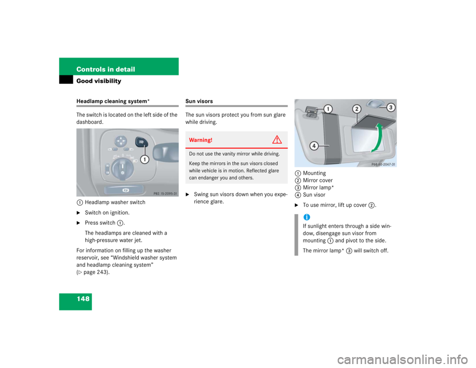
Sun visors
The sun visors protect you from sun glare
while driving.�
Swing sun visors down when you expe-
rience glare. 1
Mounting
2 Mirror cover
3 Mirror lamp*
4 Sun visor
�
To use mirror, lift up cover 2.
Warning!
G
Do not use the vanity mirror while driving.
Keep the mirrors in the sun visors closed
while vehicle is in motion. Reflected glare
can endanger you and others.
iIf sunlight enters through a side win-
dow, disengage sun visor from
mounting 1 and pivot to the side.
The mirror lamp* 3 will switch off.
Page 176 of 376

176 Controls in detailAudio systemUse only original CDs. Using copied CDs
may create problems during playback.
Clean CDs from time to time with a com-
mercially available cleaning cloth. Do not
use solvents, anti-static sprays, etc. for
cleaning. Replace the CD in its case after
use. Protect CDs from heat and direct sun-
light.
Only use CDs, which bear the label shown
and that conform to the compact disc
digital audio standard (IEC 60908). You
can therefore only use CDs with a maxi-
mum thickness of 1.3 mm.Operational readiness of CD changer
If a CD changer has been installed in the
system, it can be operated from the front
control panel of the radio. A loaded maga-
zine must be installed to play CDs.
Loading/unloading the CD magazine
�
Slide changer door to the right and
press eject button
g.
�
The magazine will be ejected.
iUse of CDs which do not meet this
standard may cause damage to the CD
changer. Do not play single-CDs
(80 mm) with an adapter.
Your CD drive has been designed to
play CDs which correspond to the
EN 60908 standard.
If you insert thicker data carriers, e.g.
ones that have data on both sides (one
side with DVD data, the other side with
audio data), they cannot be ejected and
will damage the drive.Warning!
G
The CD changer* is a Class 1 laser product.
There is a danger of invisible laser radiation
if the cover is opened or damaged.
Do not remove the cover. The CD changer*
does not contain any parts which can be ser-
viced by the user. For safety reasons, have
any service work which may be necessary
performed only by qualified personnel.