Page 211 of 296

525
Driving tips
1
2
3
4
5
6
7
8
9
6. Return to the vehicle and firmlypress and release the pro-
grammed HomeLink button up to
three times. The rolling code
equipped device should now rec-
ognize the HomeLink signal and
activate when the HomeLink but-
ton is pressed. The remaining two
buttons may now be programmed
if this has not previously been
done. Refer to the “Programming”
portion of this text.
Operating HomeLink To operate, simply press the pro-
grammed HomeLink button.
Activation will now occur for the
trained product (garage door, securi-
ty system, entry door lock, estate
gate, or home or office lighting). For
convenience, the hand-held trans-
mitter of the device may also be used
at any time. The HomeLink Wireless
Controls System (once programmed)
or the original hand-held transmitter
may be used to activate the device
(e.g. garage door, entry door lock,
etc.). In the event that there are still
programming difficulties, contact
HomeLink at 1-800-355-3515 or on
the internet at www.homelink.com.
Erasing programmed
HomeLink buttonsTo erase the three programmed but-
tons (individual buttons cannot be
erased):
Press and hold the left and centerbuttons simultaniously, until the
indicator light begins to flash
(approximately 20 seconds).
Release both buttons. Do not hold
for longer than 30 seconds.
HomeLink is now in the train (or
learning) mode and can be pro-
grammed at any time.
MMSA5005
Flashing
Opirus CAN 5-1.qxd 7/8/03 2:21 PM Page 25
Page 212 of 296

Driving tips26
5
1
2
3
4
5
6
7
8
9
Reprogramming a single
HomeLink buttonTo program a device to HomeLink
using a HomeLink button previously
trained, follow these steps:
1. Press and hold the desired
HomeLink button. Do NOT release
until step 4 has been completed.
2. When the indicator light begins to flash slowly (after 20 seconds),
position the hand-held transmitter
3 ~ 7 cm away from the HomeLink
surface.
3. Press and hold the hand-held transmitter button (or press and
“cycle” - as described in
“Canadian Programming” above).
4. The HomeLink indicator light will flash, first slowly and then rapidly.
When the indicator light begins to
flash rapidly, release both buttons.
The previous device has now been
erased and the new device can be
activated by pushing the HomeLink
button that has just been pro-
grammed. This procedure will not
affect any other programmed
HomeLink buttons.
Gate operator programming &
canadian programmingDuring programming, your hand-held
transmitter may automatically stop
transmitting. Continue to press and
hold the HomeLink button (note
steps 2 through 4 in the
“Programming” portion of this text)
while you press and re-press
(“cycle”) your handheld transmitter
every two seconds until the frequen-
cy signal has been learned. The indi-
cator light will flash slowly and then
rapidly after several seconds upon
successful training.✽ ✽ NOTICEIf programming a garage door
opener or gate, it is advised to
unplug the device during the
“cycling” process to prevent possi-
ble motor burn-up.
AccessoriesIf you would like additional informa-
tion on the HomeLink Wireless
Control System, HomeLink compati-
ble products, or to purchase other
accessories such as the HomeLink®
Lighting Package, please contact
HomeLink at 1-800-355-3515 or on
the internet at www.homelink.com.
This device complies with FCC rules
part 15. Operation is subject to the
following two conditions:
(1) This device may not cause harm-
ful interference.
(2) This device must accept any
interference that may be received
including interference that may
cause undesired operation.
Opirus CAN 5-1.qxd 7/8/03 2:21 PM Page 26
Page 215 of 296
In case of an emergency26ROAD WARNING Hazard warning flasher The hazard warning flasher serves
as a warning to other drivers to exer-
cise extreme caution when
approaching, overtaking, or passing
your vehicle. It should be used when-
ever emergency repairs are being
made or when the vehicle is stopped
near the edge of a roadway.Depress the flasher switch with the
ignition switch in any position. The
flasher switch is located in the center
console switch panel. All turn signal
lights will flash simultaneously.
• The hazard warning flasher oper-
ates whether your vehicle is run-
ning or not.
The turn signals do not work when the hazard flasher is on.
Care must be taken when using the hazard warning flasher while
the vehicle is being towed.
1
2
3
4
5
6
7
8
9
ESP
2GHA2051B
Opirus CAN 6-1.qxd 7/8/03 2:22 PM Page 2
Page 220 of 296
67
In case of an emergency
ELECTRICAL CIRCUIT PROTECTION Fuses A vehicle’s electrical system is pro-
tected from electrical overload dam-
age by fuses.
This vehicle has two fuse panels,
one located in the driver's side knee
bolster, the other in the engine com-
partment near the battery.If any of your vehicle’s lights, acces-
sories, or controls do not work, check
the appropriate circuit fuse. If a fuse
has blown, the element inside the
fuse will be melted.
If the electrical system does not
work, first check the driver’s side
fuse panel.
Always replace a blown fuse with
one of the same rating.
If the replacement fuse blows, this
indicates an electrical problem. Avoid
using the system involved and imme-
diately consult an Authorized Kia
Dealer.
Two kinds of fuses are used: stan-
dard for lower amperage rating andmain for higher amperage ratings.
1
2
3
4
5
6
7
8
9
MMSA6003
Standard
Main fuse
Normal Normal Blown
Blown
Opirus CAN 6-1.qxd 7/8/03 2:22 PM Page 7
Page 221 of 296

In case of an emergency86Fuse replacement
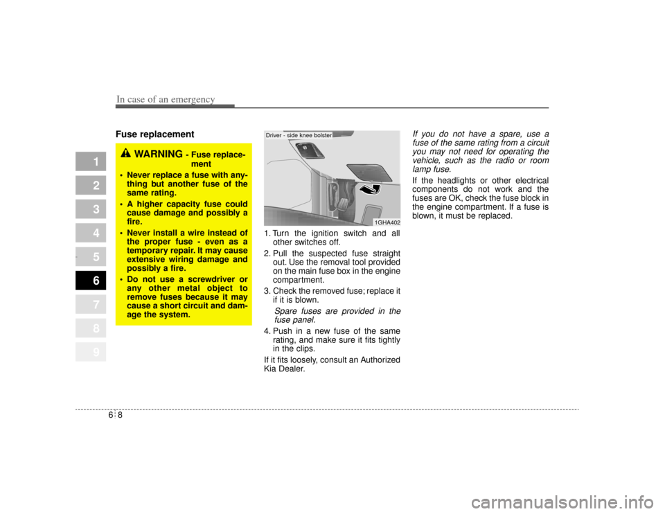
1. Turn the ignition switch and allother switches off.
2. Pull the suspected fuse straight out. Use the removal tool provided
on the main fuse box in the engine
compartment.
3. Check the removed fuse; replace it if it is blown.
Spare fuses are provided in thefuse panel.
4. Push in a new fuse of the same rating, and make sure it fits tightly
in the clips.
If it fits loosely, consult an Authorized
Kia Dealer.
If you do not have a spare, use a fuse of the same rating from a circuityou may not need for operating thevehicle, such as the radio or roomlamp fuse.If the headlights or other electrical
components do not work and the
fuses are OK, check the fuse block in
the engine compartment. If a fuse is
blown, it must be replaced.
1
2
3
4
5
6
7
8
9
1GHA402
WARNING
- Fuse replace-
ment
Never replace a fuse with any- thing but another fuse of the
same rating.
A higher capacity fuse could cause damage and possibly a
fire.
Never install a wire instead of the proper fuse - even as a
temporary repair. It may cause
extensive wiring damage and
possibly a fire.
Do not use a screwdriver or any other metal object to
remove fuses because it may
cause a short circuit and dam-
age the system.
Driver - side knee bolster
Opirus CAN 6-1.qxd 7/8/03 2:22 PM Page 8
Page 223 of 296
In case of an emergency10
6
1
2
3
4
5
6
7
8
9
Relay panel description
ETS
H/LAMP
(LO-RH)
DRL*
(TAIL)
DRL*
(RESISTOR)
H/LP
WASHER*
Passenger-side panel
Engine compartment
2GHN601/2GHN602
Relay name Relay description
Passenger - side panel
BLOWER (HI) Air conditioner blower relay (high)
Engine compartment
H/LP WASHER* Head lamp washer relay
ETS Electronic throttle system relay
DRL (RESISTOR)* Daytime running light (Resistor) relay
DRL (TAIL)* Daytime running light (Taillight) relay
H/LAMP (LO-RH) Headlight relay (low beam-right)
Opirus CAN 6-1.qxd 7/8/03 2:22 PM Page 10
Page 224 of 296

611
In case of an emergency
1
2
3
4
5
6
7
8
9
Fuse/Relay panel descriptionInside the fuse/relay box covers, you can find the fuse/relay label describing fuse/relay name and capacity.
C/FAN20A
FUSE
PULLER
P/SEAT(FR) 30A
H/
LP (LO-LH) HORN
START
IGN SW-2 30A
R/FAN 30A R/FAN
A/CON FAN-2WIPER (LO)
TAIL
LP
H/LP (HI)
A/CON FAN-1
FOG
LP(FR)
FUEL PUMP A/CON
16
2738
11 12 16 20
15
14
17
1822
23
19 25 24
27
21
13
9
10
4
5 28
26
IGN SW-1
30A
ABS 230A
ABS 1 30A
1. FUEL PUMP
2. H/LP (LO-LH)
3. ABS
4. INJECTOR
5. A/CON COMP
6. ATM RLY
7. ECU RLY
8. IGN COIL
9. O2 SNSR
10. ENG SNSR
(20A)
(15A)
(10A)
(10A)
(10A)
(20A)
(20A)
(20A)
(15A)
(15A)
11. HORN
12. TAIL LP
13. H/LP WASHER
14. ETS
15. FOG LP (FR)
16. H/LP (HI)
17. SPARE
18. SPARE
19. SPARE
20. SPARE
(15A)
(20A)
(20A)
(20A)
(15A)
(15A)
(30A)
(20A)
(15A)
(10A)
21. BLOWER MTR
22. S/WARMER
23. AMP
24. DRL
25. H/LP (LO-RH)
26. P/FUSE-1
27. ECU
28. ECS NOT USED
(30A)
(30A)
(20A)
(15A)
(15A)
(30A)
(10A)
(15A)
USE THE DESIGNATED FUSE AND RELAY ONLT.
Engine compartment
10A
B/ALARM
15A
A/BAG
20A
C/LIGHTER
10AS/WARMER20AP/WDW(RH)15AP/HANDLE15AT/SIG LP30AHTD GLASS15A
TRUNK OPEN
SHUNT CONN
USE ONLY DESIGNATED FUSE ONLY
POWER/CONN
15ASTOP LP
10A
MIRROR HTD
10ALAN UNIT
10AB/ALARM
10ADR LP
15AAV.CLOCK
30AP/SEAT(RR)
10A
BACK WARN'G
10AROOM LP
15AF/LID OPEN
10ATAIL LP(RH)
10ATAIL LP(LH)
15A
FOG LP(RR), PIC
20AP/WDW(LH)
10AEPS
10A
CURTAIN(RR)
10AA/CON
20AWIPER(FR)
10A
LAN UNIT 10A
H/LP 10A
CLOCK
20A
P/OUTLET 10A
T/REDUCER
10A
AV
10A
A/BAG IND 10A
B/UP LP
10A
CLUSTER 10A
ENG SNSR
10A
TRIP COMPUTER
2GHN603/2GHN604
Driver-side knee bolster
Opirus CAN 6-1.qxd 7/8/03 2:22 PM Page 11
Page 225 of 296

In case of an emergency12
6
1
2
3
4
5
6
7
8
9
Description Fuse rating Protected component
1 FUEL PUMP 20A Fuel pump
2 H/LP (LO-LH) 15A Headlight (low-left)
3 ABS 10A Anti-lock brake system
4 INJECTOR 10A Injector
5 A/CON COMP 10A Air-conditioner compressor
6 ATM RLY 20A Automatic transaxle control relay
7 ECU RLY 20A Engine control unit relay
8 IGN COIL 20A Ignition coil
9 O2 SNSR 15A Oxygen sensor
10 ENG SNSR 15A
Power train control system sensors
11 HORN 15A Horn
12 TAIL LP 20A Tail light
13 H/LP WASHER 20A Headlight washer
14 ETS 20A Electronic throttle system
15 FOG LP (FR) 15A Fog light (front)
16 H/LP (HI) 15A Headlight (high)
17 SPARE 30A spare fuse
18 SPARE 20A spare fuse
19 SPARE 15A spare fuse
20 SPARE 10A spare fuse
21 BLOWER MTR 30A Blower motor
22 S/WARMER 30A Seat warmer
23 AMP 20A Radio amplifier
24 DRL* 15A Daytime running light
Description Fuse rating Protected component
25 H/LP (LO-RH) 15A Headlight (low beam-right)
26 P/FUSE-1 30A All electrical system
27 ECU 10A Engine control unit
28 ECS 15A Electronic control suspension
! NOT USED Not used
C/FAN 20A Condenser fan
P/SEAT (FR) 30A Power seat (front)
IGN SW-1 30A Ignition switch
ABS 2 30A Anti-lock brake system
ABS 1 30A Anti-lock brake system
IGN SW-2 30A Ignition switch
R/FAN 30A Radiator fan
H/LP (LO-LH) - Headlight relay (low beam-left)
FUEL PUMP - Fuel pump relay
HORN - Horn relay
START - Start motor relay
A/CON - Air conditioner relay
A/CON FAN-1 - Air conditioner fan relay
H/LP (HI) - Headlight relay (high beam)
R/FAN - Radiator fan relay
FOG LP (FR) - Fog light relay (front)
TAIL LP - Taillight relay
WIPER (LO) - Wiper relay (low)
A/CON FAN-2 - Air conditioner fan relay
Engine compartment
Opirus CAN 6-1.qxd 7/8/03 2:22 PM Page 12