Page 2688 of 4264
6E–112 ENGINE DRIVEABILITY AND EMISSIONS
22 1. Command the fuel pump ON with the Scan Tool.
2. Using suitable pliers which will not damage the
fuel hose, gradually apply pressure with the pliers
to pinch the flex ible fuel return hose closed.376 kPa
(55 psi)
Does the fuel pressure indicated by the fuel pressure
gauge rise above the first specified value?
Caution: Do not let the fuel pressure exceed the
second specified value.414 kPa
(60 psi) Go to Step 11Go to Step 7
23 1. Command the fuel pump ON with the Scan Tool.
2. Remove the fuel filler cap and listen for the sound
of the fuel pump running.
3. Turn the pump off.
Was the fuel pump running?—Go to Step 7Go to Fuel
System
Electrical Test
Chart Step Action Value(s) Yes No
Page 2787 of 4264

ENGINE DRIVEABILITY AND EMISSIONS 6E–211
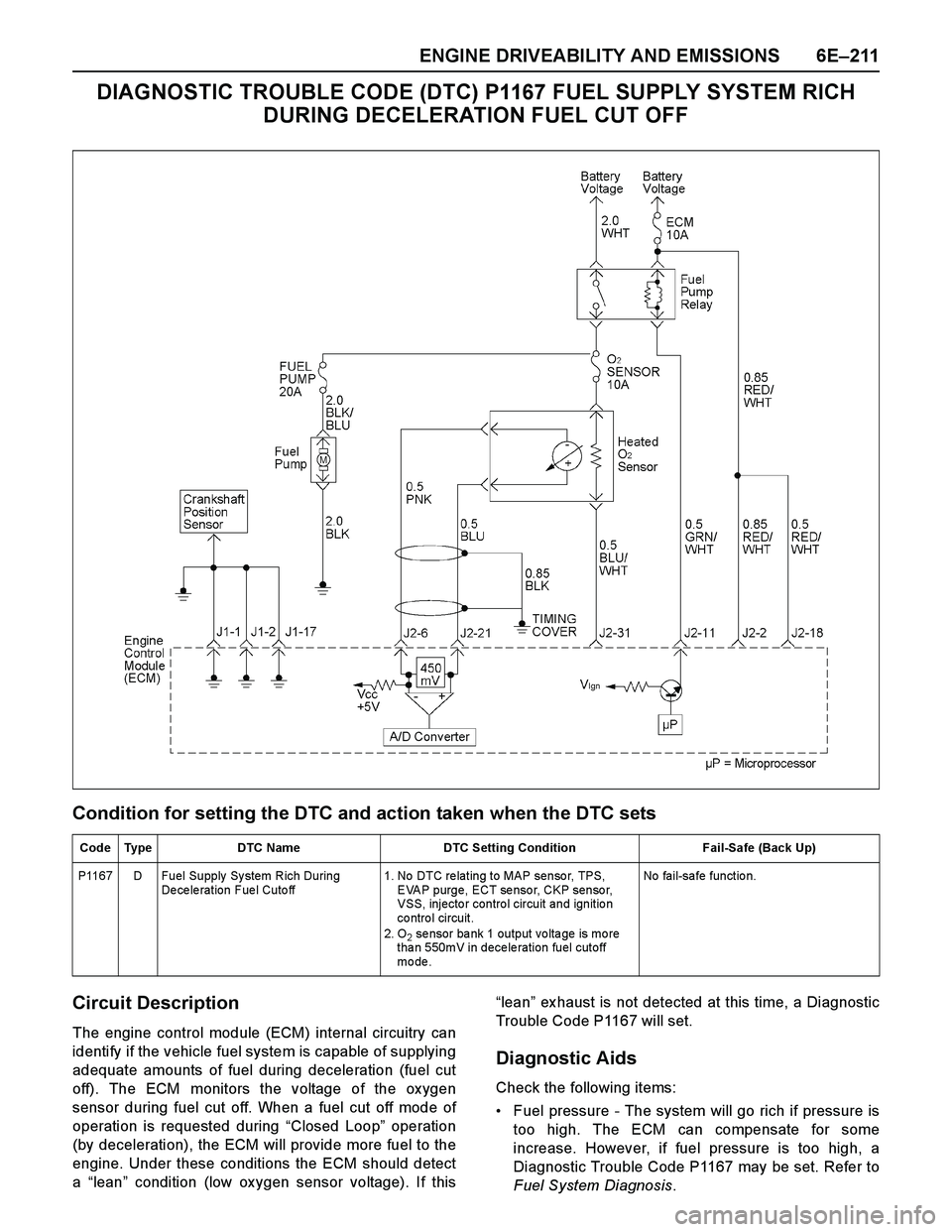
DIAGNOSTIC TROUBLE CODE (DTC) P1167 FUEL SUPPLY SYSTEM RICH
DURING DECELERATION FUEL CUT OFF
Condition for setting the DTC and action taken when the DTC sets
Circuit Description
The engine control module (ECM) internal circuitry can
identify if the vehicle fuel system is capable of supplying
adequate amounts of fuel during deceleration (fuel cut
off). The ECM monitors the voltage of the ox ygen
sensor during fuel cut off. When a fuel cut off mode of
operation is requested during “Closed Loop” operation
(by deceleration), the ECM will provide more fuel to the
engine. Under these conditions the ECM should detect
a “lean” condition (low ox ygen sensor voltage). If this“lean” ex haust is not detected at this time, a Diagnostic
Trouble Code P1167 will set.
Diagnostic Aids
Check the following items:
Fuel pressure - The system will go rich if pressure is
too high. The ECM can compensate for some
increase. However, if fuel pressure is too high, a
Diagnostic Trouble Code P1167 may be set. Refer to
Fuel System Diagnosis.
Code Type DTC Name DTC Setting Condition Fail-Safe (Back Up)
P1167 D Fuel Supply Sy stem Rich During
De ce le ration Fue l Cuto ff1. No DTC re lating to MAP senso r, TPS,
EVAP purge, ECT sensor, CKP sensor,
VSS, injecto r contro l circuit and ignitio n
co ntro l circuit.
2. O
2 se nsor ba nk 1 output vo lta ge is mo re
than 550mV in deceleration fuel cutoff
mo de .No fail-safe function.
Page 2790 of 4264

6E–214 ENGINE DRIVEABILITY AND EMISSIONS
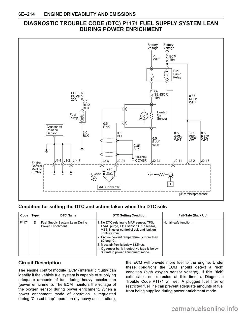
DIAGNOSTIC TROUBLE CODE (DTC) P1171 FUEL SUPPLY SYSTEM LEAN
DURING POWER ENRICHMENT
Condition for setting the DTC and action taken when the DTC sets
Circuit Description
The engine control module (ECM) internal circuitry can
identify if the vehicle fuel system is capable of supplying
adequate amounts of fuel during heavy acceleration
(power enrichment). The ECM monitors the voltage of
the ox ygen sensor during power enrichment. When a
power enrichment mode of operation is requested
during “Closed Loop” operation (by heavy acceleration),the ECM will provide more fuel to the engine. Under
these conditions the ECM should detect a “rich”
condition (high ox ygen sensor voltage). If this “rich”
ex haust is not detected at this time, a Diagnostic
Trouble Code P1171 will set. A plugged fuel filter or
restricted fuel line can prevent adequate amounts of fuel
from being supplied during power enrichment mode.
Code Type DTC Name DTC Setting Condition Fail-Safe (Back Up)
P1171 D Fuel Supply System Lean During
Po wer Enrichment 1. No DTC re lating to MAP senso r, TPS,
EVAP purge, ECT sensor, CKP sensor,
VSS, injecto r contro l circuit and ignitio n
co ntro l circuit.
2. Engine coolant temperature is more than
60 de g. C.
3. Ma ss a ir flo w is below 13.5m/s.
4. O
2 sensor bank 1 output voltage is below
350mV in power enrichment mode. No fail-safe function.
Page 2834 of 4264

6E–258 ENGINE DRIVEABILITY AND EMISSIONS
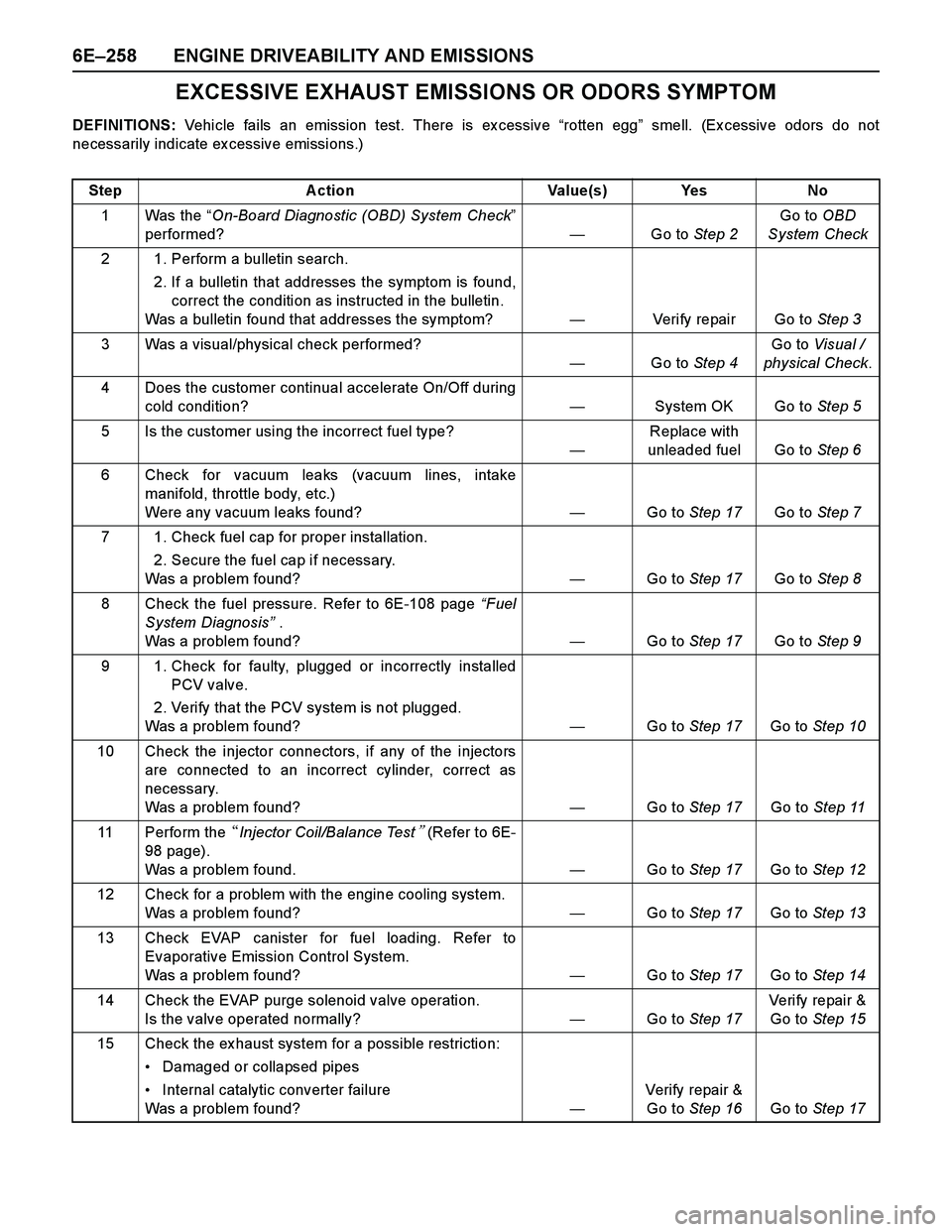
EXCESSIVE EXHAUST EMISSIONS OR ODORS SYMPTOM
DEFINITIONS: Vehicle fails an emission test. There is ex cessive “rotten egg” smell. (Ex cessive odors do not
necessarily indicate ex cessive emissions.)
Step Action Value(s) Yes No
1Was the “On-Board Diagnostic (OBD) System Check”
performed?—Go to Step 2Go to OBD
System Check
2 1. Perform a bulletin search.
2. If a bulletin that addresses the symptom is found,
correct the condition as instructed in the bulletin.
Was a bulletin found that addresses the symptom?—Verify repair Go to Step 3
3 Was a visual/physical check performed?
—Go to Step 4Go to Visual /
physical Check.
4 Does the customer continual accelerate On/Off during
cold condition?—System OK Go to Step 5
5 Is the customer using the incorrect fuel type?
—Replace with
unleaded fuel Go to Step 6
6 Check for vacuum leaks (vacuum lines, intake
manifold, throttle body, etc.)
Were any vacuum leaks found?—Go to Step 17Go to Step 7
7 1. Check fuel cap for proper installation.
2. Secure the fuel cap if necessary.
Was a problem found?—Go to Step 17Go to Step 8
8 Check the fuel pressure. Refer to 6E-108 page “Fuel
System Diagnosis” .
Was a problem found?—Go to Step 17Go to Step 9
9 1. Check for faulty, plugged or incorrectly installed
PCV valve.
2. Verify that the PCV system is not plugged.
Was a problem found? —Go to Step 17Go to Step 10
10 Check the injector connectors, if any of the injectors
are connected to an incorrect cylinder, correct as
necessary.
Was a problem found?—Go to Step 17Go to Step 11
11 Perform the �Injector Coil/Balance Test� (Refer to 6E-
98 page).
Was a problem found.—Go to Step 17Go to Step 12
12 Check for a problem with the engine cooling system.
Was a problem found?—Go to Step 17Go to Step 13
13 Check EVAP canister for fuel loading. Refer to
Evaporative Emission Control System.
Was a problem found?—Go to Step 17Go to Step 14
14 Check the EVAP purge solenoid valve operation.
Is the valve operated normally?—Go to Step 17Veri fy repai r &
Go to Step 15
15 Check the ex haust system for a possible restriction:
Damaged or collapsed pipes
Internal catalytic converter failure
Was a problem found?—Verify repair &
Go to Step 16Go to Step 17
Page 2846 of 4264

6E–270 ENGINE DRIVEABILITY AND EMISSIONS
FUEL PRESSURE RELIEF
Caution: To reduce the risk of fire and personal
injury, it is necessary to relieve the fuel system
pressure before servicing the fuel system
components.
Caution: After relieving the fuel system pressure, a
small amount of fuel may be released when
servicing fuel lines or connections. Reduce the
chance of personal injury by covering the fuel line
fitting with a short towel before disconnecting the
fittings. The towel will absorb any fuel that may leak
out. When the disconnect is completed, place the
towel in an approved container.
1. Remove the fuel filler cap.
2. Remove the fuel pump relay from the underhood
relay box .
3. Start the engine and allow it to stall.
4. Crank the engine for about 30 seconds.
5. Disconnect the negative battery cable.
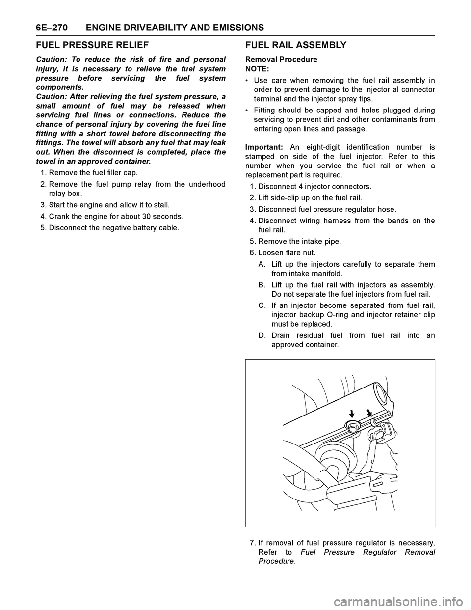
FUEL RAIL ASSEMBLY
Removal Procedure
NOTE:
Use care when removing the fuel rail assembly in
order to prevent damage to the injector al connector
terminal and the injector spray tips.
Fitting should be capped and holes plugged during
servicing to prevent dirt and other contaminants from
entering open lines and passage.
Important: An eight-digit identification number is
stamped on side of the fuel injector. Refer to this
number when you service the fuel rail or when a
replacement part is required.
1. Disconnect 4 injector connectors.
2. Lift side-clip up on the fuel rail.
3. Disconnect fuel pressure regulator hose.
4. Disconnect wiring harness from the bands on the
fuel rail.
5. Remove the intake pipe.
6. Loosen flare nut.
A. Lift up the injectors carefully to separate them
from intake manifold.
B. Lift up the fuel rail with injectors as assembly.
Do not separate the fuel injectors from fuel rail.
C. If an injector become separated from fuel rail,
injector backup O-ring and injector retainer clip
must be replaced.
D. Drain residual fuel from fuel rail into an
approved container.
7. If removal of fuel pressure regulator is necessary,
Refer to Fuel Pressure Regulator Removal
Procedure.