Page 2535 of 4264
 6C-11
140R100028
Reuse of Quick–Connector
Replace the port and connector if scratch, dent or
crack is found.
Remove any dirt build up on the port when installin")
ENGINE FUEL (C24SE) 6C-11
140R100028
Reuse of Quick–Connector
Replace the port and connector if scratch, dent or
crack is found.
Remove any dirt build up on the port when installing
the connector. Replace the connector, if there is any
forms of rust, dent, scratch.
After cleaning the port, insert it straight into the
connector until it clicks. After it clicks, try pulling a
t
49N (5kgf) it out to make sure that it is not drawn
and is securely locked.
140R100036
Assembling Advice
By applying engine oil or light oil to the pipe, port makes
pipe assembly easier. The pipe assembly should take
place immediately after applying oil (to prevent dus
t
from sticking to the pipe surface –which may
decrease sealing ability).
Test/Inspection After Assembling
1. Reconnect the battery negative cable.
2. Turn the ignition key to the “ON" position and listen
for pump start-up sound. Inspect for leaks, the
fuel pressure will increase as the fuel pump is
actuated.
3. Perform leak inspection (step 2) several times.
4. Start the engine and observe the engine idle speed.
The presence of dirt in the fuel system may affec
t
the fuel injection system.
Page 2549 of 4264

IGNITION SYSTEM 6D2-1
SECTION 6D2
IGNITION SYSTEM
CONTENTS
PAGE
General Description........................................................................................................ 6D2- 2
Service Precaution ......................................................................................................... 6D2- 2
Diagnosis......................................................................................................................... 6D2- 2
Ignition Coil ..................................................................................................................... 6D2- 2
Removal ...................................................................................................................... 6D2- 2
Installation .................................................................................................................. 6D2- 2
Spark Plug ....................................................................................................................... 6D2- 3
Removal ...................................................................................................................... 6D2- 3
Inspection and Repair................................................................................................ 6D2- 3
Installation .................................................................................................................. 6D2- 4
Crankshaft Angle Sensor ............................................................................................... 6D2- 4
Removal ...................................................................................................................... 6D2- 4
Installation .................................................................................................................. 6D2- 4
Main Data and Specifications ........................................................................................ 6D2- 5
Page 2550 of 4264

6D2-2 IGNITION SYSTEM
General Description
Ignition is done by the Ignition Module that fires.
Since the cylinder on exhaust stroke requires less energy to
fire its spark plug, energy from the ignition coils can be utilized
to fire the mating cylinder on compression stroke.
A notch in the timing disc on the crankshaft activates the crank
angle sensor which then sends information such as firing order
and starting timing of ignition coil to the ECM.
By receiving signals such as crank position, engine speed,
water temperature and Manifold Absolute Pressure (MAP), the
ECM controls the ignition timing.
Service Precaution
CAUTION:
Always use the correct fastener in the proper location.
When you replace a fastener, use ONLY the exact part
number for that application. ISUZU will call out those
fasteners that require a replacement after removal. ISUZU
will also call out the fasteners that require thread lockers
or thread sealant. UNLESS OTHERWISE SPECIFIED, do
not use supplemental coatings (Paints, greases, or other
corrosion inhibitors) on threaded fasteners or fastener
joint interfaces. Generally, such coatings adversely affect
the fastener torque and the joint clamping force, and may
damage the fastener. When you install fasteners, use the
correct tightening sequence and specifications. Following
these instructions can help you avoid damage to parts
and systems.
Diagnosis
Refer to Section Drivability and Emissions for the diagnosis to
electronic ignition system (El system).
Ignition Coil
Removal
1. Disconnect battery ground cable.
2. Disconnect the Ignition coil connector.
3. Remove the ignition coil.
Installation
1. Install the ignition coil.
Connect ignition coil connector and ignition coil, then tighten
bolt to the specified torque.
Torque: 20 N�
�� �m (2.0 kgf�
�� �m)
2. Connect battery ground cable.
Page 2551 of 4264

IGNITION SYSTEM 6D2-3
Spark Plug
Removal
1. Remove spark plugs.
Inspection and Repair
The spark plug affects entire engine performance and
therefore its inspection is very important.
�
Check electrode and insulator for presence of cracks, and
replace if any.
�
Check electrode for wear, and replace if necessary.
�
Check gasket for damage, and replace if necessary.
�
Measure insulation resistance with an ohmmeter, and
replace if faulty.
� Adjust spark plug gap to 1.0 - 1.1 mm (0.027 in) - 0.8 mm
(0.031 in).
�
Check fuel and electrical systems if spark plug is extremel
y
dirty.
�
Use spark plugs having low heat value (hot type plug) if fuel
and electrical systems are normal.
�
Use spark plugs having high heat value (cold type plug) i
f
insulator and electrode are extremely burned.
Sooty Spark Plugs
Much deposit of carbon or oil on the electrode and insulator of
spark plug reduces the engine performance.
Possible causes:
� Too rich mixture
�
Presence of oil in combustion chamber
�
Incorrectly adjusted spark plug gap
Burning Electrodes
This fault is characterized by scorched or heavily oxidized
electrode or blistered insulator nose.
Possible causes:
�
Too lean mixture
�
Improper heat value
Measuring Insulation Resistance
�
Measure insulation resistance using a 500 volt megaohm
meter.
� Replace spark plugs if measured value is out of standard.
Insulation resistance: 50 M
�
�� � or more
Page 2552 of 4264
6D2-4 IGNITION SYSTEM
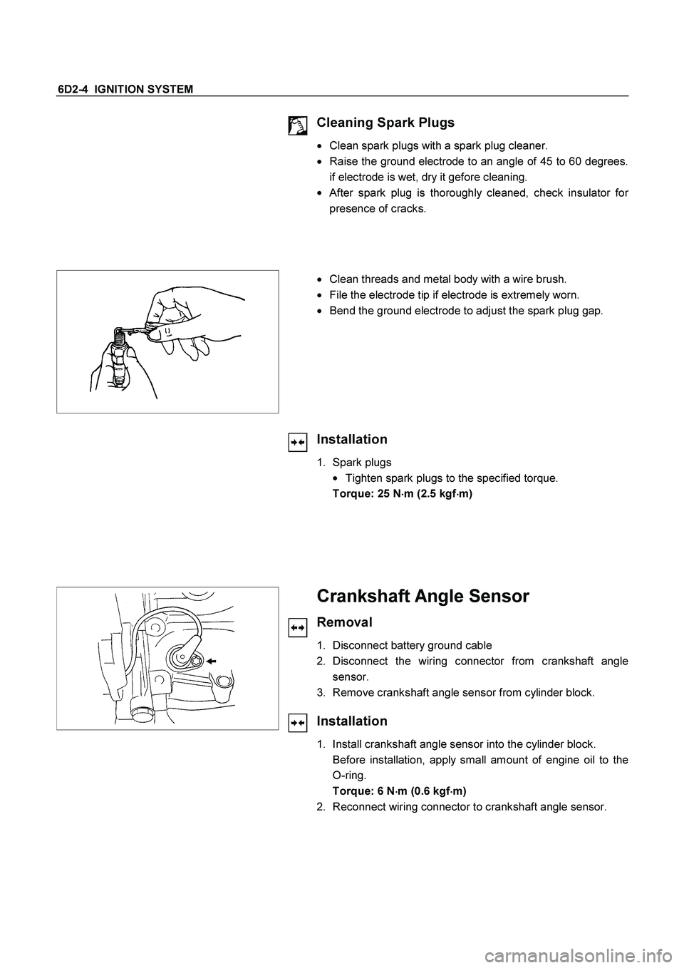
Cleaning Spark Plugs
�
Clean spark plugs with a spark plug cleaner.
� Raise the ground electrode to an angle of 45 to 60 degrees.
if electrode is wet, dry it gefore cleaning.
�
After spark plug is thoroughly cleaned, check insulator for
presence of cracks.
�
Clean threads and metal body with a wire brush.
�
File the electrode tip if electrode is extremely worn.
�
Bend the ground electrode to adjust the spark plug gap.
Installation
1. Spark plugs
�
Tighten spark plugs to the specified torque.
Torque: 25 N
�
�� �m (2.5 kgf
�
�� �m)
Crankshaft Angle Sensor
Removal
1. Disconnect battery ground cable
2. Disconnect the wiring connector from crankshaft angle
sensor.
3. Remove crankshaft angle sensor from cylinder block.
Installation
1. Install crankshaft angle sensor into the cylinder block.
Before installation, apply small amount of engine oil to the
O-ring.
Torque: 6 N
�
�� �m (0.6 kgf
�
�� �m)
2. Reconnect wiring connector to crankshaft angle sensor.
Page 2553 of 4264
IGNITION SYSTEM 6D2-5
Main Data and Specifications
General Specifications
Ignition System
Ignition Form Electronic Ignition System (El system) with Crankshaft angle Sensor
Spark Plug
Type
No. of Coils and Type
Coil Location
Torque Electronic Spark Control
2 Solid State
Engine-mounted
20 N�m (2.0 kgf�m)
Page 2559 of 4264

STARTING AND CHARGING SYSTEM 6D3-5
Inspection and Repair
Repair or replace necessary parts if extreme wear or damage
is found during inspection.
Armature
Check for continuity between commutator and segment.
Replace commutator if there is no continuity (i.e.,
disconnected).
Check for continuity between commutator and shaft.
Also, check for continuity between commutator and armature
core, armature core and shaft. Replace commutator if there is
continuity (i.e., internally grounded).
Brush
Measure the length of brush.
Replace with a new one, if it is below the limit.
Brush Holder
Check for continuity between brush holder (+) (4) and base (-).
Replace, if there is continuity (i.e., insulation is broken).
Magnetic Switch
Check for continuity of shunt coil between terminals S and M.
Replace, if there is no continuity (i.e., coil is disconnected).
Continuity of Series Coil
Check for continuity between terminals S and M.
Replace, if there is no continuity (i.e., coil is disconnected).
Page 2561 of 4264
STARTING AND CHARGING SYSTEM 6D3-7
Charging System
General Description
The charging system is an IC integral regulator charging
system and its main components are connected as shown in
illustration.
The regulator is a solid state type and it is mounted along with
the brush holder assembly inside the generator installed on the
rear end cover.
The generator does not require particular maintenance such as
voltage adjustment. The rectifier connected to the stator coil
has eight diodes to transform AC voltage into DC voltage.
This DC voltage is connected to the output terminal of
generator.
Legend
1 Startor assembly
2 Housing
3 Slipring
4 Screws (2)
5 Regulator
6.Bolt (4)7 Rectifier assem bly
8 Retaining assem bly
9 B+ terminal nut and washer
10 Pulley
11 Rotor assembly
12 Ball bearing
2
11
12
28 54
31
11 7 6 10
9
 with Crankshaft angle Sensor
Spark Plug
Type")
