Page 2614 of 4264
6E–38 ENGINE DRIVEABILITY AND EMISSIONS
ECM WIRING DIAGRAM (6/9)
Page 2615 of 4264
ENGINE DRIVEABILITY AND EMISSIONS 6E–39
ECM WIRING DIAGRAM (7/9)
Page 2616 of 4264
6E–40 ENGINE DRIVEABILITY AND EMISSIONS
ECM WIRING DIAGRAM (8/9)
Page 2617 of 4264
ENGINE DRIVEABILITY AND EMISSIONS 6E–41
ECM WIRING DIAGRAM (9/9)
Page 2618 of 4264

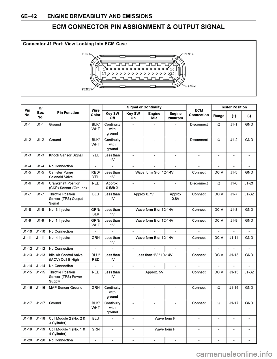
6E–42 ENGINE DRIVEABILITY AND EMISSIONS
ECM CONNECTOR PIN ASSIGNMENT & OUTPUT SIGNAL
Connector J1 Port: View Looking Into ECM Case
1
1716
32
PIN16 PIN1
PIN17PIN3
2
Pin
No. B/
Box
No.P in FunctionWire
ColorSignal or Continuity
ECM
ConnectionTester Position
Key SW
OffKey SW
OnEngine
IdleEngine
2000rpmRange (+) (-)
J1-1 J1-1 Ground BLK/
WH TContinuity
with
gro und- - - Disconnect�J1-1 GND
J1-2 J1-2 Ground BLK/
WH TContinuity
with
gro und- - - Disconnect�J1-2 GND
J1-3 J1-3 Knock Sensor Signal YEL Less than
1V--- ----
J1 -4 J1 -4 No Co n ne ct io n - - - - - - - - -
J1-5 J1-5 Caniste r Purge
So le no id Valv e RED/
YELLess tha n
1VWav e fo rm G or 12-14V Co nnect DC V J1-5 GND
J1-6 J1-6 Cra nkshaft Positio n
(CKP) Se nsor (Ground)RED Approx .
0.58k�- - - Disconnect�J1-6 J1-21
J1-7 J1-7 Throttle Po sition
Se nsor (TPS) Output
SignalBLU Less tha n
1VAppro x 0.7V Appro x
0.8VCo nnect DC V J1-7 J1-32
J1-8 J1-8 No. 3 Injecto r GRN/
BLKLess tha n
1VWav e fo rm E o r 12-14V Co nnect DC V J1-8 GND
J1-9 J1-9 No. 1 Injecto r GRN/
WH TLess tha n
1VWav e fo rm E o r 12-14V Co nnect DC V J1-9 GND
J1-10 J1-10 No Connection - - - - - - - - -
J1-11 J1-11 No. 4 Injecto r GRN Less tha n
1VWav e fo rm E o r 12-14V Co nnect DC V J1-11 GND
J1-12 J1-12 No Connection - - - - - - - - -
J1-13 J1-13 Idle Air Contro l Va lv e
(IACV) Co il B HighBLU/
REDLess tha n
1VLess than 1V / 10-14V Connect DC V J1-13 GND
J1-14 J1-14 No Connection - - - - - - - - -
J1-15 J1-15 Throttle Po sition
Se nsor (TPS) Po wer
Supply RED Less tha n
1VApprox. 5V Connect DC V J1-15 J1-32
J1-16 J1-16 MAP Senso r Gro und GRN Continuity
with
gro und- - - Connect�J1-16 GND
J1-17 J1-17 Ground BLK/
WH TContinuity
with
gro und- - - Connect�J1-17 GND
J1-18 J1-18 Coil Mo dule 2 (No. 2 &
3 Cylinde r)BLU - - Wa v e form F - - - -
J1-19 J1-19 Coil Mo dule 1 (No. 1 &
4 Cylinde r)GRN - - Wa v e form F - - - -
J1-20 J1-20 No Connection - - - - - - - - -
Page 2619 of 4264

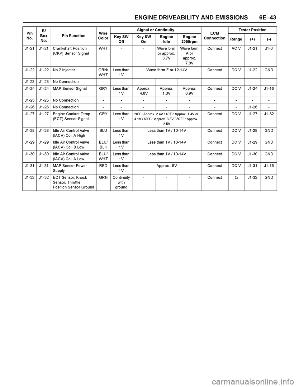
ENGINE DRIVEABILITY AND EMISSIONS 6E–43
J1-21 J1-21 Crankshaft Position
(CKP) Se nsor Signa lWHT - - Wave form
or approx.
3.7VWa v e f o r m
A o r
approx.
7.8VCo nnect AC V J1-21 J1-6
J1-22 J1-22 No.2 Injecto r GRN/
WH TLess tha n
1VWav e fo rm E o r 12-14V Co nnect DC V J1-22 GND
J1-23 J1-23 No Connection - - - - - - - - -
J1-24 J1-24 MAP Sensor Signal GRY Less than
1VApprox.
4.8VApprox.
1.3VApprox.
0.9VCo nnect DC V J1-24 J1-16
J1-25 J1-25 No Connection - - - - - - - - -
J1-26 J1-26 No Connection - - - - - - - J1-26 -
J1-27 J1-27 Engine Coo la nt Temp.
(ECT) Se nsor Signa lGRY Less tha n
1V
20�: Approx. 2.4V / 40�: Approx . 1.4V or
4.1V / 60�: Approx . 3.3V / 80�: Approx .
2.5VCo nnect DC V J1-27 J1-32
J1-28 J1-28 Idle Air Contro l Va lv e
(IACV) Co il A HighBLU Less tha n
1VLess than 1V / 10-14V Connect DC V J1-28 GND
J1-29 J1-29 Idle Air Contro l Va lv e
(IACV) Co il B LowBLU/
BLKLess tha n
1VLess than 1V / 10-14V Connect DC V J1-29 GND
J1-30 J1-30 Idle Air Contro l Va lv e
(IACV) Co il A LowBLU/
WH TLess tha n
1VLess than 1V / 10-14V Connect DC V J1-30 GND
J1-31 J1-31 MAP Sensor Power
SupplyRED Less tha n
1VAppro x.. 5V Co nnect DC V J1-31 J1-16
J1-32 J1-32 ECT Sensor, Knock
Se nsor, Thro ttle
Po sitio n Senso r GroundGRN Continuity
with
gro und- - - Connect�J1-32 GND Pin
No. B/
Box
No.P in FunctionWire
ColorSignal or Continuity
ECM
ConnectionTester Position
Key SW
OffKey SW
OnEngine
IdleEngine
2000rpmRange (+) (-)
Page 2620 of 4264

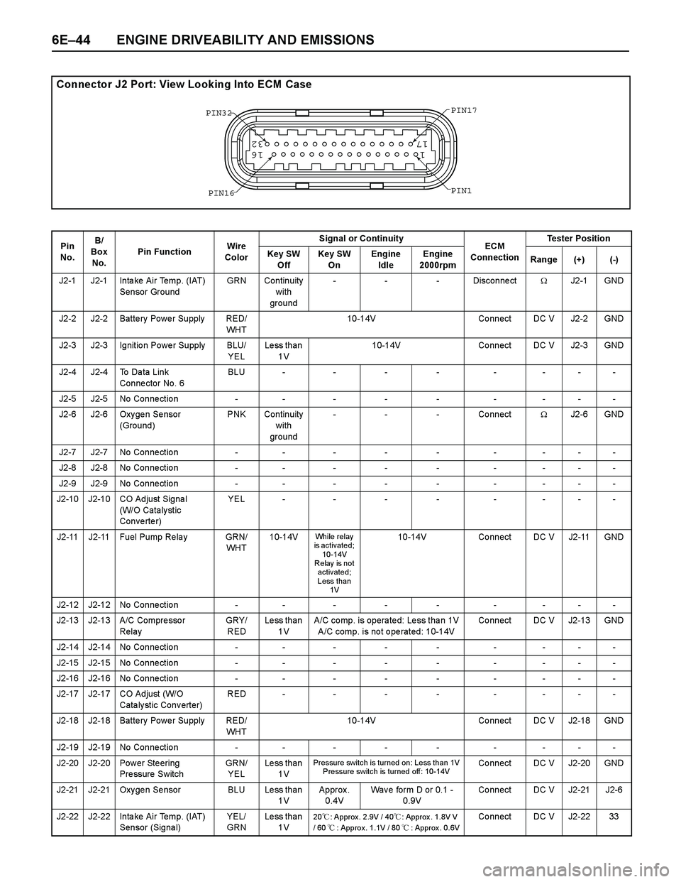
6E–44 ENGINE DRIVEABILITY AND EMISSIONS
Connector J2 Port: View Looking Into ECM Case
1
1716
32
PIN32
PIN1 PIN17
PIN16
Pin
No. B/
Box
No.Pin FunctionWire
ColorSignal or Continuity
ECM
ConnectionTester Position
Key SW
OffKey SW
OnEngine
IdleEngine
2000rpmRange (+) (-)
J2-1 J2-1 Inta ke Air Temp. (IAT)
Sensor GroundGRN Continuity
with
ground- - - Disconnect�J2-1 GND
J2-2 J2-2 Batte ry Powe r Supply RED/
WH T10-14V Co nnect DC V J2-2 GND
J2-3 J2-3 Ignitio n Powe r Supply BLU/
YELLess than
1V10-14V Connect DC V J2-3 GND
J2-4 J2-4 To Da ta Link
Conne ctor No. 6BLU - - - - - - - -
J2-5 J2-5 No Connection - - - - - - - - -
J2-6 J2-6 Oxy ge n Se nsor
(Ground)PNK Continuity
with
ground- - - Connect�J2-6 GND
J2-7 J2-7 No Connection - - - - - - - - -
J2-8 J2-8 No Connection - - - - - - - - -
J2-9 J2-9 No Connection - - - - - - - - -
J2-10 J2-10 CO Adjust Signa l
(W/O Cata ly stic
Converter)YEL - - - - - - - -
J2-11 J2-11 Fuel Pump Re la y GRN/
WH T10-14V
While relay
is activated;
10-14V
R elay is no t
activated;
Less than
1V10-14V Connect DC V J2-11 GND
J2-12 J2-12 No Connection - - - - - - - - -
J2-13 J2-13 A/C Compre sso r
RelayGRY/
REDLess than
1VA/C comp. is operated: Less than 1V
A/C comp. is not operated: 10-14VCo nnect DC V J2-13 GND
J2-14 J2-14 No Connection - - - - - - - - -
J2-15 J2-15 No Connection - - - - - - - - -
J2-16 J2-16 No Connection - - - - - - - - -
J2-17 J2-17 CO Adjust (W/O
Cata ly stic Conv erter)RED - - - - - - - -
J2-18 J2-18 Batte ry Powe r Supply RED/
WH T10-14V Co nnect DC V J2-18 GND
J2-19 J2-19 No Connection - - - - - - - - -
J2-20 J2-20 Pow er Ste ering
Pressure SwitchGRN/
YELLess than
1V
Pressure switch is turned on: Less than 1V
Pressure switch is turned off: 10-14VCo nnect DC V J2-20 GND
J2-21 J2-21 Oxygen Sensor BLU Less than
1VApprox .
0.4VWave form D or 0.1 -
0.9V Co nnect DC V J2-21 J2-6
J2-22 J2-22 Inta ke Air Temp. (IAT)
Sensor (Signa l)YEL/
GRNLess than
1V
20�: Approx. 2.9V / 40�: Approx . 1.8V V
/ 60�: Approx. 1.1V / 80�: Approx . 0.6VCo nnect DC V J2-22 33
Page 2621 of 4264

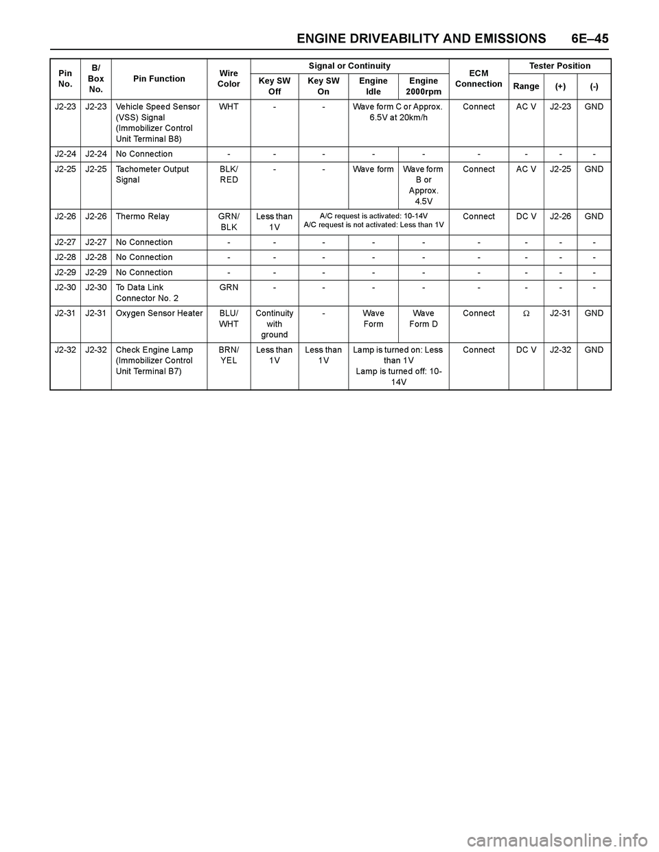
ENGINE DRIVEABILITY AND EMISSIONS 6E–45
J2-23 J2-23 Vehicle Speed Sensor
(VSS) Signal
(Immobilize r Co ntrol
Unit Terminal B8)WHT - - Wave form C or Approx.
6.5V at 20km/hCo nnect AC V J2-23 GND
J2-24 J2-24 No Connection - - - - - - - - -
J2-25 J2-25 Ta cho me te r Output
Signa lBLK/
RED- - Wa v e f o r m Wa v e f o r m
B or
Approx.
4.5VCo nnect AC V J2-25 GND
J2-26 J2-26 Thermo Relay GRN/
BLKLess than
1V
A/C request is activ ated: 10-14V
A/C request is not activated: Less than 1VCo nnect DC V J2-26 GND
J2-27 J2-27 No Connection - - - - - - - - -
J2-28 J2-28 No Connection - - - - - - - - -
J2-29 J2-29 No Connection - - - - - - - - -
J2-30 J2-30 To Da ta Link
Conne ctor No. 2GRN - - - - - - - -
J2-31 J2-31 Oxy ge n Se nso r He ater BLU/
WH TContinuity
with
ground- Wave
FormWa v e
Form DConnect�J2 -31 GND
J2-32 J2-32 Check Engine Lamp
(Immobilize r Co ntrol
Unit Terminal B7)BRN/
YELLess than
1VLess than
1VLa mp is turne d on: Less
than 1V
Lamp is turne d off: 10-
14VCo nnect DC V J2-32 GND Pin
No. B/
Box
No.Pin FunctionWire
ColorSignal or Continuity
ECM
ConnectionTester Position
Key SW
OffKey SW
OnEngine
IdleEngine
2000rpmRange (+) (-)