Page 2937 of 4264
SHEET METAL 2B-5
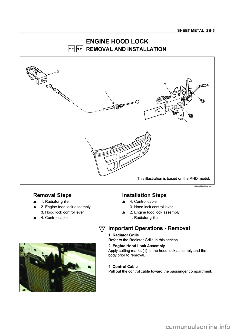
ENGINE HOOD LOCK
REMOVAL AND INSTALLATION
This illustration is based on the RHD model.
RTW42BMF000101
Removal Steps
Installation Steps
�
1. Radiator grille
�
4. Control cable
�
2. Engine food lock assembly
3. Hood lock control lever
3. Hood lock control lever
�
2. Engine food lock assembly
�
4. Control cable
1. Radiator grille
Important Operations - Removal
1. Radiator Grille
Refer to the Radiator Grille in this section.
2. Engine Hood Lock Assembly
Apply setting marks (1) to the hood lock assembly and the
body prior to removal.
4. Control Cable
Pull out the control cable toward the passenger compartment.
Page 2939 of 4264
SHEET METAL 2B-7
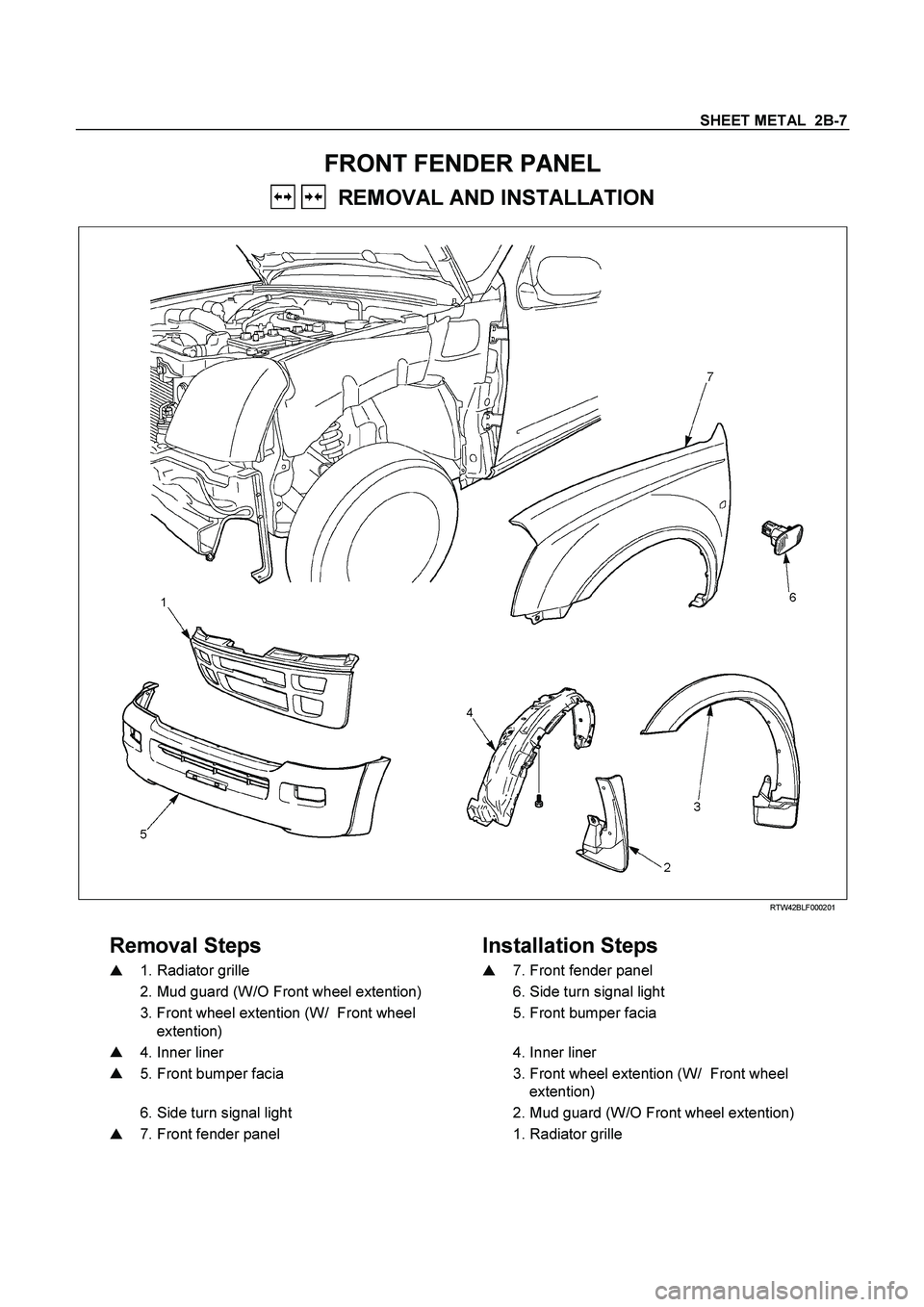
FRONT FENDER PANEL
REMOVAL AND INSTALLATION
RTW42BLF000201
Removal Steps
Installation Steps
�
1. Radiator grille
�
7. Front fender panel
2. Mud guard (W/O Front wheel extention)
6. Side turn signal light
3. Front wheel extention (W/ Front wheel
extention)
5. Front bumper facia
�
4. Inner liner
4. Inner liner
� 5. Front bumper facia
3. Front wheel extention (W/ Front wheel
extention)
6. Side turn signal light
2. Mud guard (W/O Front wheel extention)
�
7. Front fender panel
1. Radiator grille
Page 2940 of 4264
2B-8 SHEET METAL
Important Operations - Removal
1. Radiator Grille
Refer to the Radiator Grille in this section.
4. Inner liner
Remove the inner liner fixing screws.
5. Front bumper facia
Refer to the Front Bumper in this section.
7. Front fender panel
Remove the eight fixing bolts.
Important Operation - Installation
7. Front Fender Panel
1) Tighten the front fender panel fixing bolts to the
specified torque.
Torque N�m(kgf�m/lb�in)
10 (1.0
/ 87)
Page 2942 of 4264
2B-10 SHEET METAL
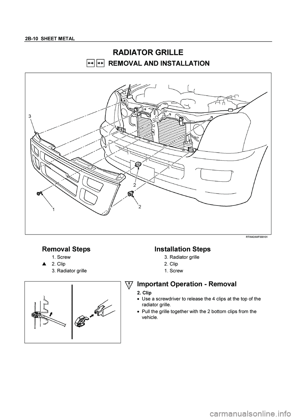
RADIATOR GRILLE
REMOVAL AND INSTALLATION
RTW42AMF000101
Removal Steps
Installation Steps
1. Screw
3. Radiator grille
�
2. Clip
2. Clip
3. Radiator grille
1. Screw
Important Operation - Removal
2. Clip
�
Use a screwdriver to release the 4 clips at the top of the
radiator grille.
�
Pull the grille together with the 2 bottom clips from the
vehicle.
Page 2978 of 4264
0A-6 GENERAL INFORMATION
IDENTIFICATION
CHASSIS NUMBER
The chassis number is stamped on the right-hand side of the
chassis side member under the right door.
VEHICLE IDENTIFICATION PLATE
The vehicle identification plate is attached to the upper face of
the radiator sill in the engine compartment.
BODY AND OPTION IDENTIFICATION
PLATE
The body and option plate shows body style, body serial
number, paint and trim colour combination, paint number,
engine transmissions, axle ratio options and built date. The
built date is defined as 'the date of manufacture' by the
calendar month and year in which the body shell and power
train sub-assemblies are co-joined or moved from the
production line.
Page 3046 of 4264

This illustration is based on RHD model RTW410LF000501
Removal Steps
1. Radiator grille
2. Fr")
1-36 HEATER AND AIR CONDITIONING
CONDENSER
REMOVAL AND INSTALLATION (4JA1-TC, 4JH1-TC)
This illustration is based on RHD model RTW410LF000501
Removal Steps
1. Radiator grille
2. Front bumper fascia
�
Refer to SECTION 2A “FRONT
BUMPER”
3. Front bumper inpact support assembly
�
Refer to SECTION 2A “FRONT
BUMPER”
4. Air cleaner assembly
5. Inter cooler
�
Refer to SECTION 6A “INTER COOLER”
6. Engine hood lock
7. Engine hood front end stay
8. Pressure switch connector
9. Condenser fan connector
10. Refrigerant line
11. Refrigerant line
12. Receiver/drier bracket
13. Receiver/drier
14. Condenser assembly
Installation Steps
14. Condenser assembly
13. Receiver/drier
12. Receiver/drier bracket
11. Refrigerant line
10. Refrigerant line
9. Condenser fan connector
8. Pressure switch connector
7. Engine hood front end stay
6. Engine hood lock
5. Inter cooler
�
Refer to SECTION 6A “INTER COOLER”
4. Air cleaner assembly
3. Front bumper inpact support assembly
�
Refer to SECTION 2A “FRONT
BUMPER”
2. Front bumper fascia
�
Refer to SECTION 2A “FRONT
BUMPER”
1. Radiator grille
Page 3047 of 4264
HEATER AND AIR CONDITIONING 1-37
REMOVAL AND INSTALLATION (EXCEPT 4JA1-TC, 4JH1-TC)
RTW410LF000701
Removal Steps
1. Radiator grille
2. Engine hood lock
3. Engine hood front end stay
4. Pressure switch connector
5. Condenser fan connector
6. Refrigerant line
7. Refrigerant line
8. Receiver/drier bracket
9. Receiver/drier
10. Condenser assembly
Installation Steps
10. Condenser assembly
9. Receiver/drier
8. Receiver/drier bracket
7. Refrigerant line
6. Refrigerant line
5. Condenser fan connector
4. Pressure switch connector
3. Engine hood front end stay
2. Engine hood lock
1. Radiator grille
Page 3048 of 4264
1-38 HEATER AND AIR CONDITIONING
CONDENSER FAN MOTOR
REMOVAL AND INSTALLATION
RTW410MF000101
Removal Steps
1. Radiator grille
2. Fan connector
3. Condenser fan motor
Installation Steps
3. Condenser fan motor
2. Fan connector
1. Radiator grille


RTW410LF000701
Removal Steps
1. Radiator grille
2. Engine hood lock
3. Engine hood fron")
