Page 3865 of 4449
PG-30
IPDM E/R (INTELLIGENT POWER DISTRIBUTION MODULE ENGINE ROOM)
Revision: 2004 November 2004 FX35/FX45
Removal and Installation of IPDM E/RAKS005SM
REMOVAL
1. Remove battery. Refer to SC-9, "Removal and Installation" in “Starting and Charging System (SC)” sec-
tion.
2. Remove IPDM E/R cover A. While pressing pawl on backside of
IPDM E/R cover B toward vehicle front to unlock, lift up IPDM E/
R.
3. While pressing pawls on right and left side of IPDM E/R, remove
IPDM E/R cover B from IPDM E/R.
4. Remove harness connector from IPDM E/R.
INSTALLATION
Install in the reverse order of removal.
SKIA4968E
SKIA1902E
SKIA4969E
Page 3902 of 4449
 AKS007X0
Use the chart below to find out what each wiring diagram code stands for.
Refe")
HARNESS
PG-67
C
D
E
F
G
H
I
J
L
MA
B
PG
Revision: 2004 November 2004 FX35/FX45
Wiring Diagram Codes (Cell Codes) AKS007X0
Use the chart below to find out what each wiring diagram code stands for.
Refer to the wiring diagram code in the alphabetical index to find the location (page number) of each wiring
diagram.
Code Section Wiring Diagram Name
A/C ATC Air Conditioner
APPS1 EC Accelerator Pedal Position Sensor
APPS2 EC Accelerator Pedal Position Sensor
APPS3 EC Accelerator Pedal Position Sensor
ASC/BS EC Automatic Speed Control Device (ASCD) Brake Switch
ASC/SW EC Automatic Speed Control Device (ASCD) Steering Switch
ASCBOF EC Automatic Speed Control Device (ASCD) Brake Switch
ASCIND EC Automatic Speed Control Device (ASCD) Indicator
AT/IND DI A/T Indicator Lamp
AUDIO AV Audio
AUT/DP SE Automatic Drive Positioner
AUTO/L LT Automatic Light System
AWD TF AWD Control System
B/CLOS BL Back Door Closure System
BACK/L LT Back-Up Lamp
BRK/SW EC Brake Switch
CAN AT CAN Communication Line
CAN EC CAN Communication Line
CAN LAN CAN System
CHARGE SC Charging System
CHIME DI Warning Chime
CIGAR WW Cigarette Lighter
CLOCK DI Clock
COMBSW LT Combination Switch
COMM AV Audio Visual Communication Line
COMPASS DI Compass
COOL/F EC Cooling Fan Control
D/LOCK BL Power Door Lock
DEF GW Rear Window Defogger
DTRL LT Headlamp - With Daytime Light System
ECM/PW EC ECM Power Supply For Back-Up
ECTS EC Engine Coolant Temperature Sensor
ETC1 EC Electric Throttle Control Function
ETC2 EC Electric Throttle Control Motor Relay
ETC3 EC Electric Throttle Control Motor
F/FOG LT Front Fog Lamp
F/PUMP EC Fuel Pump
FTS AT A/T Fluid Temperature Sensor Circuit
FTTS EC Fuel Tank Temperature Sensor
FUELB1 EC Fuel Injection System Function (Bank 1)
FUELB2 EC Fuel Injection System Function (Bank 2)
Page 3904 of 4449

PHSB1 EC Camshaft Position Sensor (PHASE) (Bank1)
PHSB2 EC Camshaft Position Se")
HARNESS
PG-69
C
D
E
F
G
H
I
J
L
MA
B
PG
Revision: 2004 November 2004 FX35/FX45
PHASE EC Camshaft Position Sensor (PHASE)
PHSB1 EC Camshaft Position Sensor (PHASE) (Bank1)
PHSB2 EC Camshaft Position Sensor (PHASE) (Bank2)
PNP/SW AT Park / Neutral Position Switch
PNP/SW EC Park / Neutral Position Switch
POS EC Crankshaft Position Sensor (CKPS) (POS)
POWER AT Transmission Control Module Power Supply
POWER PG Power Supply Routing
PRE/SE EC Evap Control System Pressure Sensor
PS/SEN EC Power Steering Pressure Sensor
R/VIEW DI Rear View Camera Control System
ROOM/L LT Interior Room Lamp
RP/SEN EC Refrigerant Pressure Sensor
SEAT SE Power Seat
SEN/PW EC Sensor Power Supply
SHIFT AT A/T Shift Lock System
SROOF RF Sunroof
SRS SRS Supplemental Restraint System
START SC Starting System
STOP/L LT Stop Lamp
STSIG AT Start Signal Circuit
T/WARN WT Low Tire Pressure Warning System
TAIL/L LT Parking, License and Tail Lamps
TPS1 EC Throttle Position Sensor (Sensor 1)
TPS2 EC Throttle Position Sensor (Sensor 2)
TPS3 EC Throttle Position Sensor
TRNSCV BL Homelink Universal Transceiver
TURN LT Turn Signal and Hazard Warning Lamp
VDC BRC Vehicle Dynamics Control System
VEHSEC BL Vehicle Security System
VENT/V EC Evap Canister Vent Control Valve
VIAS/V EC VIAS Control Solenoid Valve
VSSA/T AT Vehicle Speed Sensor A/T (Revolution Sensor)
WARN DI Warning Lamps
WINDOW GW Power Window
WIP/R WW Rear Wiper and Washer
WIPER WW Front Wiper and Washer Code Section Wiring Diagram Name
Page 3909 of 4449
PG-74
HARNESS CONNECTOR
Revision: 2004 November 2004 FX35/FX45
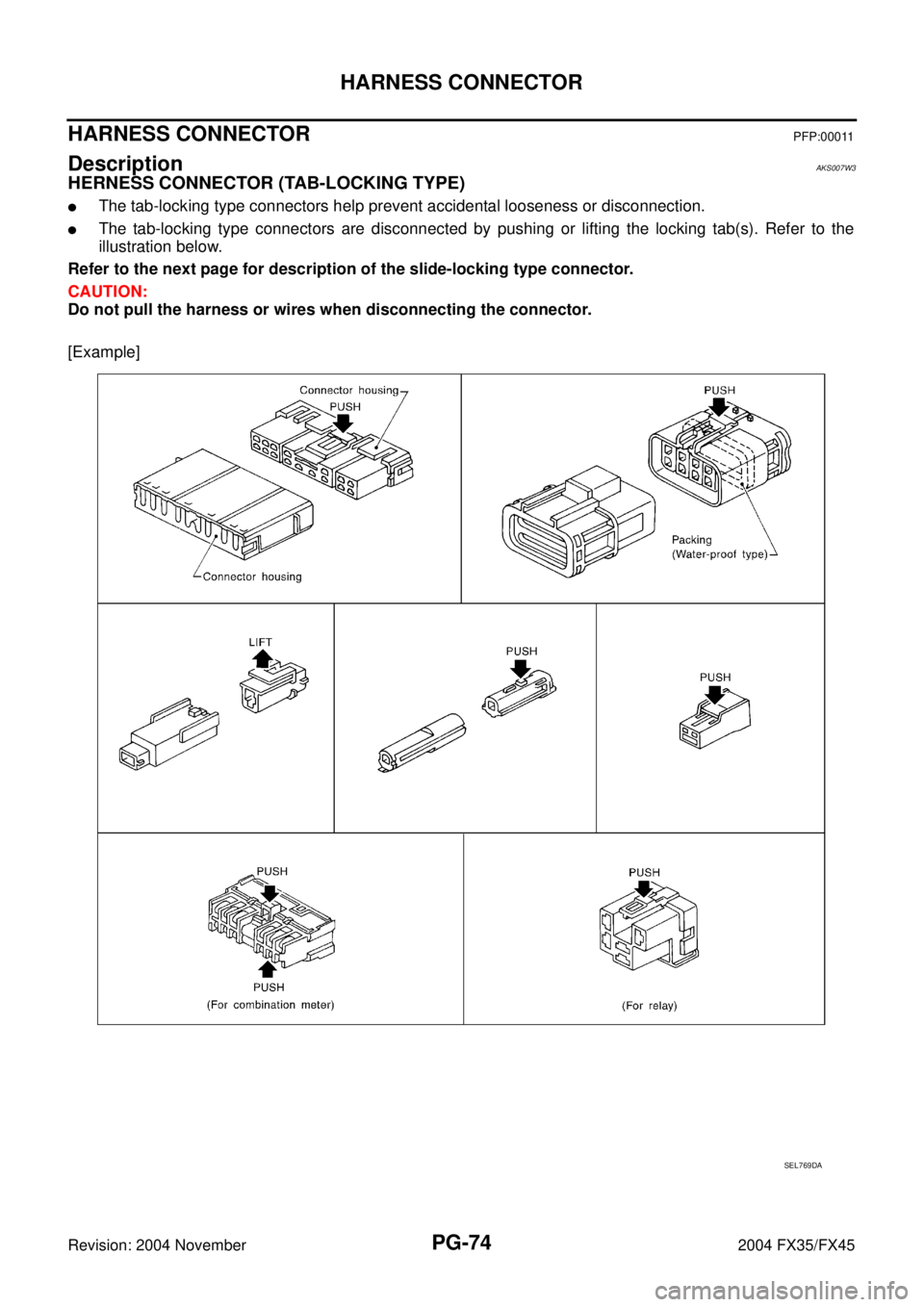
HARNESS CONNECTOR PFP:00011
DescriptionAKS007W3
HERNESS CONNECTOR (TAB-LOCKING TYPE)
�The tab-locking type connectors help prevent accidental looseness or disconnection.
�The tab-locking type connectors are disconnected by pushing or lifting the locking tab(s). Refer to the
illustration below.
Refer to the next page for description of the slide-locking type connector.
CAUTION:
Do not pull the harness or wires when disconnecting the connector.
[Example]
SEL769DA
Page 3910 of 4449
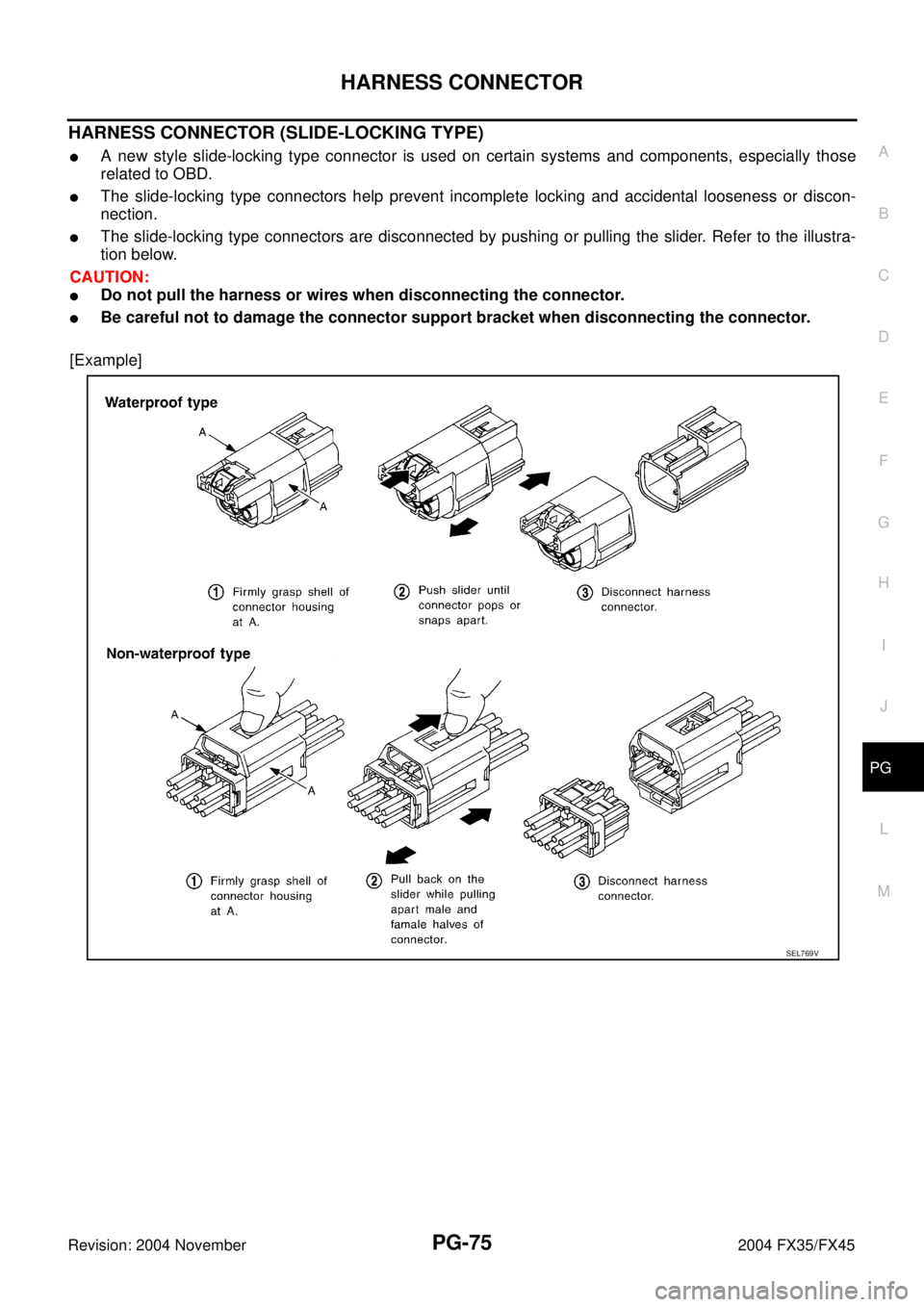
HARNESS CONNECTOR
PG-75
C
D
E
F
G
H
I
J
L
MA
B
PG
Revision: 2004 November 2004 FX35/FX45
HARNESS CONNECTOR (SLIDE-LOCKING TYPE)
�A new style slide-locking type connector is used on certain systems and components, especially those
related to OBD.
�The slide-locking type connectors help prevent incomplete locking and accidental looseness or discon-
nection.
�The slide-locking type connectors are disconnected by pushing or pulling the slider. Refer to the illustra-
tion below.
CAUTION:
�Do not pull the harness or wires when disconnecting the connector.
�Be careful not to damage the connector support bracket when disconnecting the connector.
[Example]
SEL769V
Page 3918 of 4449
FUSE BLOCK - JUNCTION BOX (J/B)
PG-83
C
D
E
F
G
H
I
J
L
MA
B
PG
Revision: 2004 November 2004 FX35/FX45
FUSE BLOCK - JUNCTION BOX (J/B)PFP:24350
Terminal ArrangementAKS007W8
CKIM0222E
Page 3921 of 4449
PR-2
PREPARATION
Revision: 2004 November 2004 FX35/FX45
PREPARATIONPFP:00002
Special Service ToolsADS000KJ
The actual shapes of Kent-Moore tools may differ from those of special service tools illustrated here.
Commercial Service ToolsADS000KC
Tool number
(Kent-Moore No.)
Tool nameDescription
KV40104000
(—)
Flange wrench
a: 85 mm (3.35 in)
b: 65 mm (2.56 in)Removing and installing center flange lock nut
ST30031000
(J-22912-01)
Puller
a: 90 mm (3.54 in) dia.
b: 50 mm (1.97 in) dia.Removing rear propeller shaft center bearing
NT659
NT411
Tool nameDescription
Power toolLoosening bolts and nuts
PBIC0190E
Page 3927 of 4449

PR-8
REAR PROPELLER SHAFT
Revision: 2004 November 2004 FX35/FX45
REMOVAL
1. Move the A/T select lever to N position and release the parking brake.
2. Remove the tunnel stay with power tool. Refer to RSU-5, "
REAR
SUSPENSION ASSEMBLY" .
3. Remove the center muffler with power tool. Refer to EX-3,
"EXHAUST SYSTEM" for details.
4. Loosen the center bearing mounting bracket (lower) fixing nuts
with power tool.
5. Put matching marks on flange and rear propeller shaft.
CAUTION:
For matching mark, use paint. Never damage the propeller
shaft flange and companion flange on the rear final drive.
6. Remove the propeller shaft fixing bolts and nuts.
7. Remove the center bearing mounting bracket (lower) fixing nuts,
remove the propeller shaft from the vehicle.
INSPECTION
1. Inspect propeller shaft runout. If runout exceeds specifications,
replace propeller shaft assembly.
1. Propeller shaft (1st shaft) 2. Center bearing assembly 3.Center bearing mounting bracket
(lower)
4. Washer 5. Center flange 6. Propeller shaft (2nd shaft)
7. Lock nut 8. Clip 9.Center bearing mounting bracket
(upper)
SDIA1520E
SDIA1577E
SDIA1522E
Propeller shaft runout limit : 0.6 mm (0.024 in) or less
SPD106

Revision: 2004 November 2004 FX35/FX45
Removal and Installation of IPDM E/RAKS005SM
REMOVAL
1. Remove battery. Refer to SC-9, \"Remova")

PG-83
C
D
E
F
G
H
I
J
L
MA
B
PG
Revision: 2004 November 2004 FX35/FX45
FUSE BLOCK - JUNCTION BOX (J/B)PFP:24350
Terminal ArrangementAKS007W8
CKIM0222E")
