Page 291 of 4449

AT-214
TROUBLE DIAGNOSIS FOR SYMPTOMS
Revision: 2004 November 2004 FX35/FX45
3. CHECK A/T FLUID LEVEL
Check A/T fluid level. Refer to AT- 1 2 , "
Checking A/T Fluid" .
OK or NG
OK >> GO TO 4.
NG >> Refill ATF.
4. CHECK LINE PRESSURE
Check line pressure at the engine stall point. Refer to AT- 5 2 , "
LINE
PRESSURE TEST" .
OK or NG
OK >> GO TO 7.
NG - 1 >> Line pressure high. GO TO 5.
NG - 2 >> Line pressure low. GO TO 6.
5. DETECT MALFUNCTIONING ITEM
1. Check control valve with TCM. Refer to AT- 2 4 2 , "
Control Valve with TCM and A/T Fluid Temperature Sen-
sor 2" .
2. Disassemble A/T. Refer to AT- 2 8 6 , "
DISASSEMBLY" .
3. Check the following items:
–Oil pump assembly. Refer to AT- 3 0 3 , "Oil Pump" .
OK or NG
OK >> GO TO 7.
NG >> Repair or replace damaged parts.
6. DETECT MALFUNCTIONING ITEM
1. Check control valve with TCM. Refer to AT- 2 4 2 , "
Control Valve with TCM and A/T Fluid Temperature Sen-
sor 2" .
2. Disassemble A/T. Refer to AT- 2 8 6 , "
DISASSEMBLY" .
3. Check the following items:
–Oil pump assembly. Refer to AT- 3 0 3 , "Oil Pump" .
–Power train system. Refer to AT- 2 8 6 , "DISASSEMBLY" .
–Transmission case. Refer to AT- 2 8 6 , "DISASSEMBLY" .
OK or NG
OK >> GO TO 7.
NG >> Repair or replace damaged parts.
SAT638A
SAT494G
Page 294 of 4449

TROUBLE DIAGNOSIS FOR SYMPTOMS
AT-217
D
E
F
G
H
I
J
K
L
MA
B
AT
Revision: 2004 November 2004 FX35/FX45
4. DETECT MALFUNCTIONING ITEM
1. Check control valve with TCM. Refer to AT- 2 4 2 , "
Control Valve with TCM and A/T Fluid Temperature Sen-
sor 2" .
2. Disassemble A/T. Refer to AT- 2 8 6 , "
DISASSEMBLY" .
3. Check the following items:
–Oil pump assembly. Refer to AT- 3 0 3 , "Oil Pump" .
OK or NG
OK >> GO TO 6.
NG >> Repair or replace damaged parts.
5. DETECT MALFUNCTIONING ITEM
1. Check control valve with TCM. Refer to AT- 2 4 2 , "
Control Valve with TCM and A/T Fluid Temperature Sen-
sor 2" .
2. Disassemble A/T. Refer to AT- 2 8 6 , "
DISASSEMBLY" .
3. Check the following items:
–Oil pump assembly. Refer to AT- 3 0 3 , "Oil Pump" .
–Power train system. Refer to AT- 2 8 6 , "DISASSEMBLY" .
–Transmission case. Refer to AT- 2 8 6 , "DISASSEMBLY" .
OK or NG
OK >> GO TO 6.
NG >> Repair or replace damaged parts.
6. CHECK A/T FLUID CONDITION
1. Remove oil pan. Refer to AT- 2 4 2 , "
Control Valve with TCM and A/T Fluid Temperature Sensor 2" .
2. Check A/T fluid condition. Refer to AT- 5 1 , "
Fluid Condition
Check" .
OK or NG
OK >> GO TO 7.
NG >> GO TO 10.
7. DETECT MALFUNCTIONING ITEM
�Check the malfunction items. If any items are damaged, repair or replace damaged parts. Refer to AT- 6 5 ,
"Symptom Chart" (Symptom No.24).
OK or NG
OK >> GO TO 8.
NG >> Repair or replace damaged parts.
8. CHECK SYMPTOM
Check again. Refer to AT- 5 7 , "
Cruise Test - Part 1" .
OK or NG
OK >>INSPECTION END
NG >> GO TO 9.
SCIA5199E
Page 319 of 4449
AT-242
ON-VEHICLE SERVICE
Revision: 2004 November 2004 FX35/FX45
ON-VEHICLE SERVICEPFP:00000
Control Valve with TCM and A/T Fluid Temperature Sensor 2ACS007GZ
COMPONENTS
CONTROL VALVE WITH TCM REMOVAL AND INSTALLATION
Removal
1. Disconnect the battery cable from the negative terminal.
2. Remove front cross bar. Refer to FSU-8, "
Components" .
3. Disconnect heated oxygen sensor 2 harness connector.
4. Drain ATF through drain plug.
5. Disconnect A/T assembly harness connector.
1. Transmission 2. Control valve with TCM 3. Bracket
4. A/T fluid temperature sensor 2 5. Oil pan gasket 6. Oil pan
7. Magnet 8. Drain plug gasket 9. Drain plug
10. Oil pan mounting bolt 11. Snap ring 12. O-ring
SCIA5137E
Page 325 of 4449
AT-248
ON-VEHICLE SERVICE
Revision: 2004 November 2004 FX35/FX45
9. Connect revolution sensor connector.
10. Securely fasten revolution sensor harness with terminal clips.
11. Install magnets in oil pan.
12. Install oil pan to transmission case.
a. Install oil pan gasket to oil pan.
CAUTION:
�Do not reuse oil pan gasket.
�Install it in the direction to align hole positions.
�Complete remove all moisture, oil and old gasket, etc. from oil pan gasket mounting surface.
b. Install oil pan (with oil pan gasket) to transmission case.
CAUTION:
�Install it so that drain plug comes to the position as
shown in the figure.
�Be careful not to pinch harnesses.
�Complete remove all moisture, oil and old gasket, etc.
from oil pan mounting surface.
SCIA5024E
SCIA3969E
SCIA5200E
SCIA2308E
Page 326 of 4449

ON-VEHICLE SERVICE
AT-249
D
E
F
G
H
I
J
K
L
MA
B
AT
Revision: 2004 November 2004 FX35/FX45
c. Tighten oil pan mounting bolts to the specified torque in numeri-
cal order as shown in the figure after temporarily tightening
them.
CAUTION:
Do not reuse oil pan mounting bolts.
13. Install drain plug to oil pan.
CAUTION:
Do not reuse drain plug gasket.
14. Pull up A/T assembly harness connector.
CAUTION:
Be careful not to damage connector.
15. Install snap ring to A/T assembly harness connector.
16. Connect A/T assembly harness connector.
17. Connect heated oxygen sensor 2 harness connector.
18. Install front cross bar. Refer to FSU-8, "
Components" .
19. Pour ATF into transmission assembly. Refer to AT- 1 2 , "
Chang-
ing A/T Fluid" .
20. Connect the battery cable to the negative terminal.
A/T FLUID TEMPERATURE SENSOR 2 REMOVAL AND INSTALLATION
Removal
1. Disconnect the battery cable from the negative terminal.
2. Remove front cross bar. Refer to FSU-8, "
Components" .
3. Disconnect heated oxygen sensor 2 harness connector.
4. Drain ATF through drain plug.
5. Remove oil pan and oil pan gasket.: 7.9 N·m (0.81 kg-m, 70 in-lb)
: 34 N·m (3.5 kg-m, 25 ft-lb)
SCIA2492E
SCIA5038E
SCIA5039E
SCIA2308E
Page 328 of 4449
ON-VEHICLE SERVICE
AT-251
D
E
F
G
H
I
J
K
L
MA
B
AT
Revision: 2004 November 2004 FX35/FX45
Installation
CAUTION:
After completing installation, check A/T fluid leakage and fluid level. Refer to AT- 1 2 , "
Changing A/T
Fluid" , AT- 1 2 , "Checking A/T Fluid" .
1. Install A/T fluid temperature sensor 2 to bracket.
2. Install A/T fluid temperature sensor 2 in control valve with TCM.
(With bracket.)
3. Connect A/T fluid temperature sensor 2 connector.
4. Securely fasten A/T fluid temperature sensor 2 harness with ter-
minal clip.
5. Install oil pan to transmission case.
a. Install oil pan gasket to oil pan.
CAUTION:
�Do not reuse oil pan gasket.
�Install it in the direction to align hole positions.
�Complete remove all moisture, oil and old gasket, etc. from oil pan mounting surface.
SCIA5264E
: 7.9 N·m (0.81 kg-m, 70 in-lb)
SCIA5302E
SCIA5023E
SCIA5146E
Page 329 of 4449
AT-252
ON-VEHICLE SERVICE
Revision: 2004 November 2004 FX35/FX45
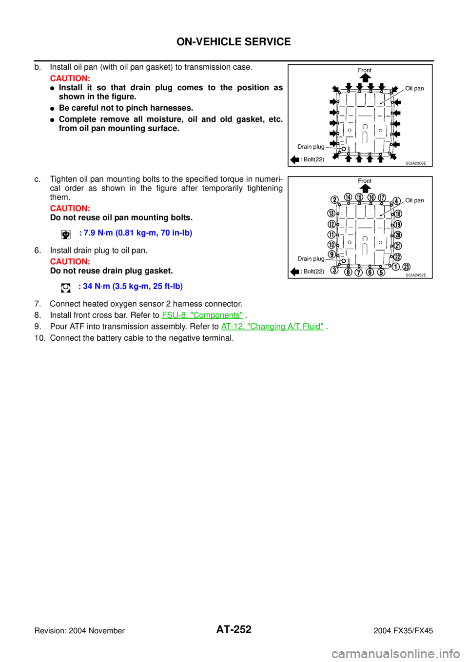
b. Install oil pan (with oil pan gasket) to transmission case.
CAUTION:
�Install it so that drain plug comes to the position as
shown in the figure.
�Be careful not to pinch harnesses.
�Complete remove all moisture, oil and old gasket, etc.
from oil pan mounting surface.
c. Tighten oil pan mounting bolts to the specified torque in numeri-
cal order as shown in the figure after temporarily tightening
them.
CAUTION:
Do not reuse oil pan mounting bolts.
6. Install drain plug to oil pan.
CAUTION:
Do not reuse drain plug gasket.
7. Connect heated oxygen sensor 2 harness connector.
8. Install front cross bar. Refer to FSU-8, "
Components" .
9. Pour ATF into transmission assembly. Refer to AT- 1 2 , "
Changing A/T Fluid" .
10. Connect the battery cable to the negative terminal.
SCIA2308E
: 7.9 N·m (0.81 kg-m, 70 in-lb)
: 34 N·m (3.5 kg-m, 25 ft-lb)
SCIA2492E
Page 330 of 4449
ON-VEHICLE SERVICE
AT-253
D
E
F
G
H
I
J
K
L
MA
B
AT
Revision: 2004 November 2004 FX35/FX45
Parking Components (2WD Models Only)ACS007H0
COMPONENTS
REMOVAL
1. Drain ATF through drain plug.
2. Remove exhaust front tube and center muffler with power tool. Refer to EX-3, "
Removal and Installation" .
3. Remove rear propeller shaft. Refer to PR-7, "
Removal and Installation" .
4. Support transmission assembly with a transmission jack.
CAUTION:
When setting transmission jack, be careful not to allow it to collide against the drain plug.
5. Remove engine rear member with power tool. Refer to AT- 2 6 6 , "
Removal and Installation (2WD Models)"
.
1. Rear oil seal 2. Rear extension 3. Parking actuator support
4. Parking pawl 5. Return spring 6. Pawl shaft
7. Self-sealing bolt 8. Seal ring 9. Parking gear
10. Output shaft 11. Bearing race 12. Needle bearing
SCIA5216E


ACS007H0
COMPONENTS
REMOVAL
1. Drain ATF through drain plug.
2. Remove ex")