Page 630 of 4449

AUDIO
AV-39
C
D
E
F
G
H
I
J
L
MA
B
AV
Revision: 2004 November 2004 FX35/FX45
Power Supply Circuit InspectionAKS00BMS
1. CHECK FUSE
�Make sure that the following fuses of the BOSE speaker amp., woofer, and audio unit are not blown.
OK or NG
OK >> GO TO 2
NG >> If fuse is blown, be sure to eliminate cause of malfunction before installing new fuse. Refer to PG-
3, "POWER SUPPLY ROUTING CIRCUIT" .
2. CHECK POWER SUPPLY CIRCUIT
1. Check voltage between the audio unit harness connector terminals and ground.
2. Turn ignition switch OFF.
3. Check voltage between BOSE speaker amp. harness connector
terminal or woofer harness connector terminal and ground.
OK or NG
OK >>�INSPECTION END (Audio unit is OK)
�GO TO 3 (BOSE speaker amp. and woofer).
NG >>
�Repair harness or connector.
Unit Signal Fuse No.
Audio unitBattery power supply 32
ACC power supply 6
BOSE speaker amp. Battery power supply 17
Woofer Battery power supply 32
UnitTerminal No.
Ignition switch Voltage (+)
(-)
Connec-
torTerminal
(Wire
color)
Audio
unitM586 (W/L) Ground OFF Battery voltage
10 (LG/R) Ground ACC Battery voltage
PKIA3814E
UnitTerminal No.
Ignition
switchVoltage (+)
(-)
ConnectorTerminal
(Wire color)
BOSE
speaker
amp.B212 1 (R) Ground OFF Battery voltage
Woofer B223 1 (GY) Ground OFF Battery voltage
SKIA8931E
Page 640 of 4449
AUDIO ANTENNA
AV-49
C
D
E
F
G
H
I
J
L
MA
B
AV
Revision: 2004 November 2004 FX35/FX45
AUDIO ANTENNAPFP:28200
System DescriptionAKS007WE
With the ignition switch in ACC or ON, power is supplied
�through 10A fuse [No. 6, located in the fuse block (J/B)]
�to audio unit terminal 10.
Ground is supplied through the case of the antenna amp.
When the radio switch is turned ON, antenna signal is supplied
�through audio unit terminal 5
�to the antenna amp.
Then the antenna amp. is activated.
The amplified radio signals are supplied to the audio unit through the antenna amp.
Page 646 of 4449

INTEGRATED DISPLAY SYSTEM
AV-55
C
D
E
F
G
H
I
J
L
MA
B
AV
Revision: 2004 November 2004 FX35/FX45
INTEGRATED DISPLAY SYSTEMPFP:28090
System DescriptionAKS00BO5
A/C AND AV SWITCH SYSTEM
Refer to Owner′s Manual for A/C and AV switch operating instructions.
Using the A/C and AV switch at the center of the instrument panel, the controls of the following systems are
centralized:
�Integrated display system (Drive computer, setting screen, etc.)
�Auto A/C system
�Audio system
PRECAUTION OF LCD MONITOR
�In order to use LED for backlight of a display, by in car temperature, brightness may change. In low tem-
perature, the refreshing rate of the picture also becomes low because of the low response of the LCD
monitor. When passenger room becomes warm, however, the LCD recovers the normal display.
�Backlight sometimes flickers or darkens according to the total consumption hours and the number of times
switched ON and OFF. In this case, display unit should be replaced. (Exchange only of backlight is impos-
sible.)
POWER SUPPLY AND GROUND
Power is supplied at all times
�through 15A fuse (No. 32, located in fuse and fusible link box)
�to display unit terminal 1, and
�to A/C and AV switch terminal 1.
When ignition switch is in ACC or ON position, power is supplied
�through 10A fuse [No. 6, located in fuse block (J/B)]
�to display unit terminal 2, and
�to A/C and AV switch terminal 2.
When ignition switch is in ON or START position, power is supplied
�through 10A fuse [No. 12, located in fuse block (J/B)]
�to display unit terminal 3.
Ground is supplied
�to display unit terminals 6 and 15, and
�to A/C and AV switch terminal 5
�through body grounds M35, M45 and M85.
Page 670 of 4449

INTEGRATED DISPLAY SYSTEM
AV-79
C
D
E
F
G
H
I
J
L
MA
B
AV
Revision: 2004 November 2004 FX35/FX45
Power Supply and Ground Circuit Check for Display UnitAKS00BOJ
1. CHECK FUSE
Make sure that the following fuses in display unit are not blown.
OK or NG
OK >> GO TO 2.
NG >> If fuse is blown be sure to eliminate case of malfunction before installing new fuse. Refer to PG-3,
"POWER SUPPLY ROUTING CIRCUIT" .
2. CHECK POWER SUPPLY CIRCUIT
Check voltage between display unit harness connector terminals
and ground.
OK or NG
OK >> GO TO 3.
NG >> Repair harness or connector.
3. CHECK GROUND CIRCUIT
1. Turn ignition switch OFF.
2. Disconnect display unit connector.
3. Check continuity between display unit harness connector M62
terminals 6 (B), 15 (B) and ground.
OK or NG
OK >> INSPECTION END
NG >> Repair harness or connector.
Unit Signal Fuse No.
Display unitBattery power supply 32
Ignition switch ACC or ON 6
Terminals Ignition switch position
(+)
(–) OFF ACC ON
ConnectorTerminal
(Wire color)
M621 (W/L) GroundBattery
voltageBattery
voltageBattery
voltage
2 (LG/R) Ground 0VBattery
voltageBattery
voltage
SKIB0373E
6, 15 – ground : Continuity should exist.
SKIA4986E
Page 671 of 4449

AV-80
INTEGRATED DISPLAY SYSTEM
Revision: 2004 November 2004 FX35/FX45
Power Supply and Ground Circuit Check for A/C and AV SwitchAKS00BOK
1. CHECK FUSE
Check if the following fuses in A/C and AV switch are blown.
OK or NG
OK >> GO TO 2.
NG >> If fuse is blown be sure to eliminate case of malfunction before installing new fuse. Refer to PG-3,
"POWER SUPPLY ROUTING CIRCUIT" .
2. CHECK POWER SUPPLY CIRCUIT
1. Check voltage between A/C and AV switch harness connector
terminals and ground.
OK or NG
OK >> GO TO 3.
NG >> Repair harness or connector.
3. CHECK GROUND CIRCUIT
1. Turn ignition switch OFF.
2. Disconnect A/C and AV switch connector.
3. Check continuity between A/C and AV switch harness connector
M64 terminal 5 (B) and ground.
OK or NG
OK >> INSPECTION END
NG >> Repair harness or connector.
Vehicle Speed Signal InspectionAKS00BOL
1. VEHICLE SPEED OPERATION CHECK
Does speedmeter is operated normally?
YES or NO
YES >> GO TO 2.
NO >> Check combination meter trouble diagnosis. Refer to DI-13, "
Diagnosis Flow" .
Unit Power source Fuse No.
A/C and AV switchBattery 32
Ignition switch ACC or ON 6
Terminals Ignition switch position
(+)
(–) OFF ACC ON
ConnectorTerminal
(Wire color)
M641 (W/L) GroundBattery
voltageBattery
voltageBattery
voltage
2 (LG/R) Ground 0VBattery
voltageBattery
voltage
SKIA8937E
5 – Ground : Continuity should exist.
SKIA4988E
Page 736 of 4449

NAVIGATION SYSTEM
AV-145
C
D
E
F
G
H
I
J
L
MA
B
AV
Revision: 2004 November 2004 FX35/FX45
Power Supply and Ground Circuit Check for NAVI Control UnitAKS00BN7
1. CHECK FUSE
Make sure that the following fuses of the NAVI control unit are not blown.
OK or NG
OK >> GO TO 2.
NG >> If fuse is blown, be sure to eliminate case of malfunction before installing new fuse. Refer to PG-3,
"POWER SUPPLY ROUTING CIRCUIT" .
2. CHECK POWER SUPPLY CIRCUIT
1. Check voltage between NAVI control unit harness connector ter-
minals and ground.
OK or NG
OK >> GO TO 3.
NG >> Repair harness or connector.
3. CHECK GROUND CIRCUIT
1. Turn ignition switch OFF.
2. Disconnect NAVI control unit connector.
3. Check continuity between NAVI control unit harness connector
B208 terminals 1 (B), 4 (B) and ground.
OK or NG
OK >> INSPECTION END
NG >> Repair harness or connector.
Unit Signal Fuse No.
NAVI control unitBattery power supply 32
ACC power supply 6
Terminals Ignition switch position
(+)
(–) OFF ACC ON
ConnectorTerminal
(Wire color)
B2082 (Y), 3 (Y)
GroundBattery
voltageBattery
voltageBattery
voltage
6 (LG) 0VBattery
voltageBattery
voltage
SKIA8932E
1, 4 – Ground : Continuity should exist.
PKIA2853E
Page 737 of 4449

AV-146
NAVIGATION SYSTEM
Revision: 2004 November 2004 FX35/FX45
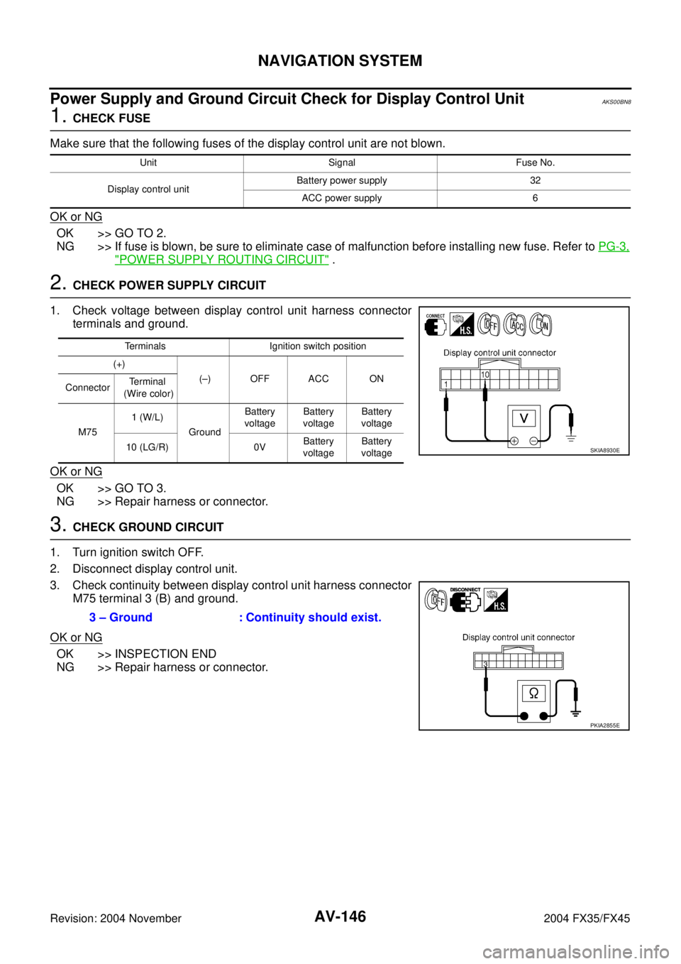
Power Supply and Ground Circuit Check for Display Control UnitAKS00BN8
1. CHECK FUSE
Make sure that the following fuses of the display control unit are not blown.
OK or NG
OK >> GO TO 2.
NG >> If fuse is blown, be sure to eliminate case of malfunction before installing new fuse. Refer to PG-3,
"POWER SUPPLY ROUTING CIRCUIT" .
2. CHECK POWER SUPPLY CIRCUIT
1. Check voltage between display control unit harness connector
terminals and ground.
OK or NG
OK >> GO TO 3.
NG >> Repair harness or connector.
3. CHECK GROUND CIRCUIT
1. Turn ignition switch OFF.
2. Disconnect display control unit.
3. Check continuity between display control unit harness connector
M75 terminal 3 (B) and ground.
OK or NG
OK >> INSPECTION END
NG >> Repair harness or connector.
Unit Signal Fuse No.
Display control unitBattery power supply 32
ACC power supply 6
Terminals Ignition switch position
(+)
(–) OFF ACC ON
ConnectorTerminal
(Wire color)
M751 (W/L)
GroundBattery
voltageBattery
voltageBattery
voltage
10 (LG/R) 0VBattery
voltageBattery
voltage
SKIA8930E
3 – Ground : Continuity should exist.
PKIA2855E
Page 740 of 4449

NAVIGATION SYSTEM
AV-149
C
D
E
F
G
H
I
J
L
MA
B
AV
Revision: 2004 November 2004 FX35/FX45
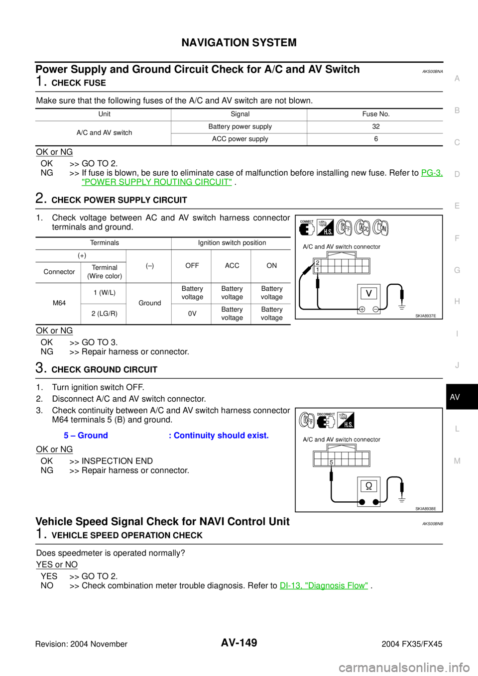
Power Supply and Ground Circuit Check for A/C and AV SwitchAKS00BNA
1. CHECK FUSE
Make sure that the following fuses of the A/C and AV switch are not blown.
OK or NG
OK >> GO TO 2.
NG >> If fuse is blown, be sure to eliminate case of malfunction before installing new fuse. Refer to PG-3,
"POWER SUPPLY ROUTING CIRCUIT" .
2. CHECK POWER SUPPLY CIRCUIT
1. Check voltage between AC and AV switch harness connector
terminals and ground.
OK or NG
OK >> GO TO 3.
NG >> Repair harness or connector.
3. CHECK GROUND CIRCUIT
1. Turn ignition switch OFF.
2. Disconnect A/C and AV switch connector.
3. Check continuity between A/C and AV switch harness connector
M64 terminals 5 (B) and ground.
OK or NG
OK >> INSPECTION END
NG >> Repair harness or connector.
Vehicle Speed Signal Check for NAVI Control UnitAKS00BNB
1. VEHICLE SPEED OPERATION CHECK
Does speedmeter is operated normally?
YES or NO
YES >> GO TO 2.
NO >> Check combination meter trouble diagnosis. Refer to DI-13, "
Diagnosis Flow" .
Unit Signal Fuse No.
A/C and AV switchBattery power supply 32
ACC power supply 6
Terminals Ignition switch position
(+)
(–) OFF ACC ON
ConnectorTe r m i n a l
(Wire color)
M641 (W/L)
GroundBattery
voltageBattery
voltageBattery
voltage
2 (LG/R) 0VBattery
voltageBattery
voltage
SKIA8937E
5 – Ground : Continuity should exist.
SKIA8938E