Page 4336 of 4449

TROUBLE DIAGNOSIS FOR SYMPTOMS
TF-35
C
E
F
G
H
I
J
K
L
MA
B
TF
Revision: 2004 November 2004 FX35/FX45
3. CHECK SYSTEM FOR AWD SOLENOID
Perform trouble diagnoses for AWD solenoid system. Refer to TF-27, "
AWD Solenoid" .
OK or NG
OK >> GO TO 4.
NG >> Repair or replace damaged parts.
4. CHECK ELECTRIC CONTROLLED COUPLING
1. Turn ignition switch “OFF”.
2. Set the selector lever to “N” (neutral) position and disengage the parking brake.
3. Lift up the vehicle.
4. Rotate the rear propeller shaft by hand.
5. Hold front propeller shaft lightly.
Does front propeller shaft rotate?
YES >> Replace electric controlled coupling for mechanical malfunction (clutch sticking etc.). Refer to TF-
45, "Disassembly and Assembly" .
NO >> GO TO 5.
5. CHECK SYMPTOM
Check again.
OK or NG
OK >>INSPECTION END
NG >> GO TO 6.
6. CHECK AWD CONTROL UNIT
Check AWD control unit input/output signal. Refer to TF-19, "
AWD Control Unit Input/Output Signal Reference
Va l u e s" .
OK or NG
OK >>INSPECTION END
NG >> Check AWD control unit pin terminals for damage or loose connection with harness connector. If
any items are damaged, repair or replace damaged parts.
Vehicle Does Not Enter AWD Mode Even Though AWD Warning Lamp Turned To
OFF
ADS000U0
DIAGNOSTIC PROCEDURE
1. CHECK AWD SOLENOID
Check AWD solenoid. Refer to TF-29, "
COMPONENT INSPECTION" .
OK or NG
OK >> GO TO 2.
NG >> Replace electric controlled coupling for malfunction of AWD solenoid. Refer to TF-45, "
Disassem-
bly and Assembly" .
2. CHECK AWD CONTROL UNIT
Check AWD control unit input/output signal. Refer to TF-19, "
AWD Control Unit Input/Output Signal Reference
Va l u e s" .
OK or NG
OK >> GO TO 3.
NG >> Check AWD control unit pin terminals for damage or loose connection with harness connector. If
any items are damaged, repair or replace damaged parts.
Page 4340 of 4449
FRONT OIL SEAL
TF-39
C
E
F
G
H
I
J
K
L
MA
B
TF
Revision: 2004 November 2004 FX35/FX45
FRONT OIL SEALPFP:38189
Removal and InstallationADS000RP
REMOVAL
1. Remove the drain plug to drain the transfer fluid. Refer to TF-8, "Replacement" .
2. Remove the front propeller shaft. Refer to PR-4, "
FRONT PROPELLER SHAFT" .
3. Remove front oil seal using a flat-bladed screwdriver.
CAUTION:
Be careful not to damage the center case.
INSTALLATION
1. Apply multi-purpose grease to oil seal lips. Install the front oil
seal with a drift until the end face of front case.
CAUTION:
�Do not reuse front oil seal.
�When installing, do not incline the oil seal.
2. Install front propeller shaft. Refer to PR-4, "
FRONT PROPEL-
LER SHAFT" .
3. Install transfer fluid, check fluid level and for fluid leakage. Refer
to TF-8, "
Inspection" .
SDIA1782E
Tool number : ST27862000 ( — )
SDIA1783E
Page 4347 of 4449
TF-46
TRANSFER ASSEMBLY
Revision: 2004 November 2004 FX35/FX45
4. Remove snap ring from front case.
5. Remove main shaft bearing from front case.
Rear Case
1. Remove the drive chain and front drive shaft from rear case.
2. Remove companion flange lock nut from main shaft using the
flange wrench.
3. Put matching mark on the end of the main shaft corresponding
to the B position matching mark on the companion flange.
SDIA1601E
SDIA1595E
SDIA1693E
Tool number : KV38108300 (J44195)
SDIA1694E
SDIA1798E
Page 4355 of 4449
TF-54
TRANSFER ASSEMBLY
Revision: 2004 November 2004 FX35/FX45
9. Install the drive chain and front drive shaft to rear case.
10. Apply liquid gasket to the entire front case mounting surface of
rear case as shown in the figure.
�Use Genuine Anaerobic Liquid Gasket or equivalent.
Refer to GI-48, "
Recommended Chemical Products and
Sealants" .
CAUTION:
Be careful not to damage the mating surface.
11. Install front case to rear case.
CAUTION:
Be careful not to damage the mating surface transmission
side.
12. Tighten bolts to specified torque.
SDIA1707E
SDIA2312E
SDIA1709E
Bolts symbol QuantityNominal length
mm (in)Tighten torque
N·m (kg-m, ft-Ib)
A 11 42 (1.65)
21.6 (2.2, 16) B 1 162 (6.38)
C 1 97 (3.82)
Torx bolts 1 40 (1.57) 18.2 (1.9, 13)
SDIA2296E
Page 4371 of 4449

WT-14
TROUBLE DIAGNOSES
Revision: 2004 November 2004 FX35/FX45
Control Unit Input/Output Signal StandardAES000NU
Standards using a circuit tester and oscilloscope.
( ): Wire color
ID Registration ProcedureAES000NV
ID REGISTRATION WITH TRANSMITTER ACTIVATION TOOL
This procedure must do after replace transmitter or low tire pressure warning control unit.
1. Turn ignition switch “OFF”.
2. Connect CONSULT-II and CONSULT-II CONVERTER to data link connector.
3. Touch “AIR PRESSURE MONITOR”, “WORK SUPPORT” and “ID REGIST”.
NOTE:
If “AIR PRESSURE MONITOR” is not indicated, go to GI-40, "
CONSULT-II Data Link Connector (DLC)
Circuit" .
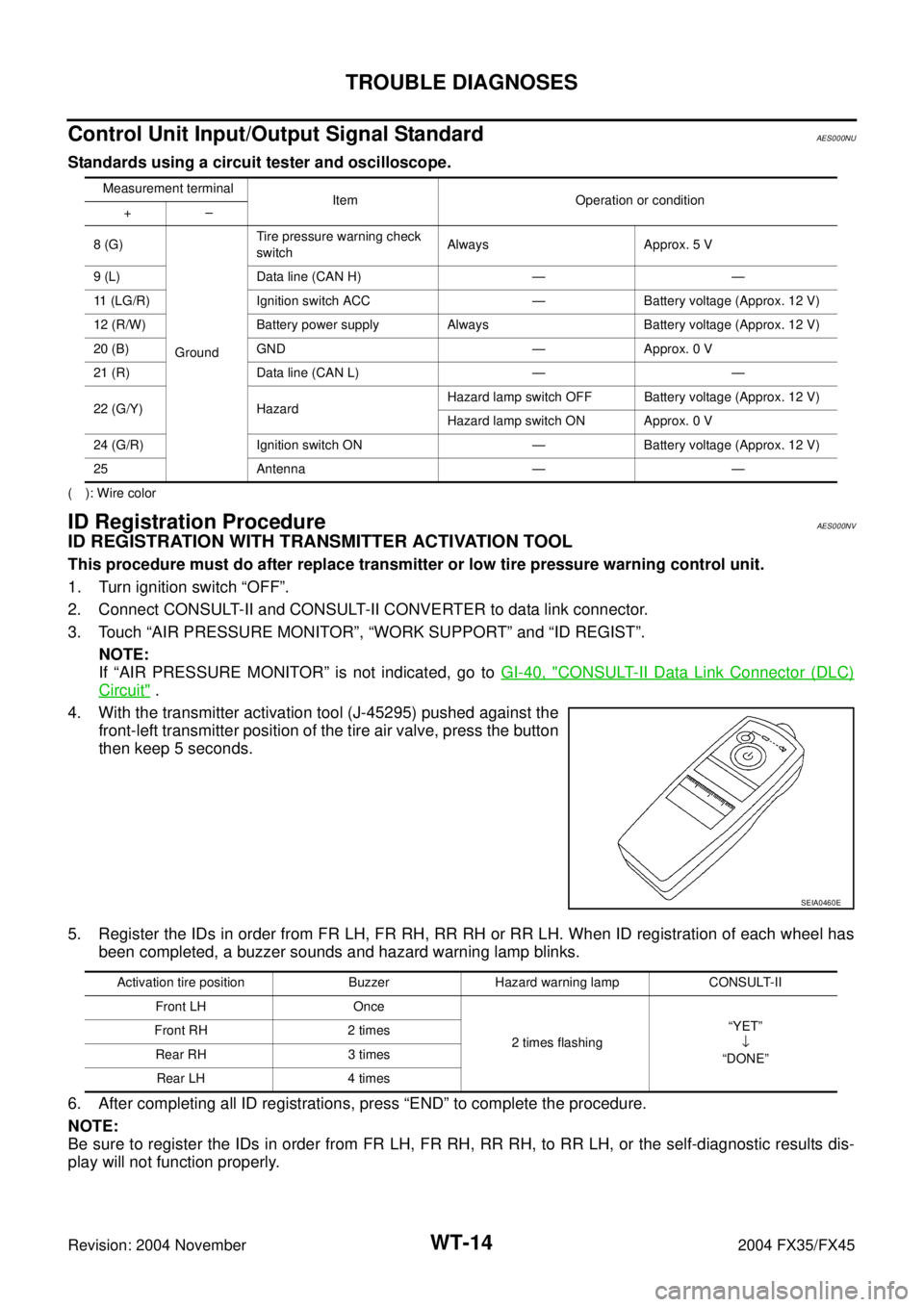
4. With the transmitter activation tool (J-45295) pushed against the
front-left transmitter position of the tire air valve, press the button
then keep 5 seconds.
5. Register the IDs in order from FR LH, FR RH, RR RH or RR LH. When ID registration of each wheel has
been completed, a buzzer sounds and hazard warning lamp blinks.
6. After completing all ID registrations, press “END” to complete the procedure.
NOTE:
Be sure to register the IDs in order from FR LH, FR RH, RR RH, to RR LH, or the self-diagnostic results dis-
play will not function properly.
Measurement terminal
Item Operation or condition
+–
8 (G)
GroundTire pressure warning check
switchAlways Approx. 5 V
9 (L) Data line (CAN H) — —
11 (LG/R) Ignition switch ACC — Battery voltage (Approx. 12 V)
12 (R/W) Battery power supply Always Battery voltage (Approx. 12 V)
20 (B) GND — Approx. 0 V
21 (R) Data line (CAN L) — —
22 (G/Y) HazardHazard lamp switch OFF Battery voltage (Approx. 12 V)
Hazard lamp switch ON Approx. 0 V
24 (G/R) Ignition switch ON — Battery voltage (Approx. 12 V)
25 Antenna — —
SEIA0460E
Activation tire position Buzzer Hazard warning lamp CONSULT-II
Front LH Once
2 times flashing“YET”
↓
“DONE” Front RH 2 times
Rear RH 3 times
Rear LH 4 times
Page 4372 of 4449
TROUBLE DIAGNOSES
WT-15
C
D
F
G
H
I
J
K
L
MA
B
WT
Revision: 2004 November 2004 FX35/FX45
ID REGISTRATION WITHOUT TRANSMITTER ACTIVATION TOOL
1. Turn ignition switch “OFF”.
2. Connect CONSULT-II and CONSULT-II CONVERTER to data link connector.
3. Touch “AIR PRESSURE MONITOR”, “WORK SUPPORT” and “ID REGIST”.
NOTE:
If “AIR PRESSURE MONITOR” is not indicated, go to GI-40, "
CONSULT-II Data Link Connector (DLC)
Circuit" .
4. Adjust the tire pressure to the values shown in the table below for ID registration, and drive the vehicle at
15 km/h (9.4 MPH) or more for a few minutes.
5. After completing all ID registrations, press “END” to complete the procedure.
Tire position
Tire pressure kPa (kg/cm2 , psi)
Front LH 250 (2.5, 36)
Front RH 230 (2.3, 33)
Rear RH 210 (2.1, 30)
Rear LH 190 (1.9, 27)
Activation tire position CONSULT-II
Front LH
“YET”
↓
“DONE” Front RH
Rear RH
Rear LH
Page 4394 of 4449

PRECAUTION
WW-3
C
D
E
F
G
H
I
J
L
MA
B
WW
Revision: 2004 November 2004 FX35/FX45
PRECAUTIONPFP:00011
Precautions for Supplemental Restraint System (SRS) “AIR BAG” and “SEAT
BELT PRE-TENSIONER”
AKS007KQ
The Supplemental Restraint System such as “AIR BAG” and “SEAT BELT PRE-TENSIONER”, used along
with a front seat belt, helps to reduce the risk or severity of injury to the driver and front passenger for certain
types of collision. This system includes seat belt switch inputs and dual stage front air bag modules. The SRS
system uses the seat belt switches to determine the front air bag deployment, and may only deploy one front
air bag, depending on the severity of a collision and whether the front occupants are belted or unbelted.
Information necessary to service the system safely is included in the SRS and SB section of this Service Man-
ual.
WARNING:
�To avoid rendering the SRS inoperative, which could increase the risk of personal injury or death
in the event of a collision which would result in air bag inflation, all maintenance must be per-
formed by an authorized NISSAN/INFINITI dealer.
�Improper maintenance, including incorrect removal and installation of the SRS, can lead to per-
sonal injury caused by unintentional activation of the system. For removal of Spiral Cable and Air
Bag Module, see the SRS section.
�Do not use electrical test equipment on any circuit related to the SRS unless instructed to in this
Service Manual. SRS wiring harnesses can be identified by yellow and/or orange harnesses or
harness connectors.
Wiring Diagrams and Trouble DiagnosisAKS0056N
When you read Wiring diagrams, refer to the following:
�Refer to GI-15, "How to Read Wiring Diagrams" .
�Refer to PG-3, "POWER SUPPLY ROUTING CIRCUIT" for power distribution circuit.
When you perform trouble diagnosis, refer to the following:
�Refer to GI-11, "How to Follow Trouble Diagnoses" .
�Refer to GI-27, "How to Perform Efficient Diagnosis for an Electrical Incident" .
Page 4396 of 4449
![INFINITI FX35 2004 Service Manual FRONT WIPER AND WASHER SYSTEM
WW-5
C
D
E
F
G
H
I
J
L
MA
B
WW
Revision: 2004 November 2004 FX35/FX45
�to front wiper high relay [located in IPDM E/R (intelligent power distribution module engine room)] INFINITI FX35 2004 Service Manual FRONT WIPER AND WASHER SYSTEM
WW-5
C
D
E
F
G
H
I
J
L
MA
B
WW
Revision: 2004 November 2004 FX35/FX45
�to front wiper high relay [located in IPDM E/R (intelligent power distribution module engine room)]](/manual-img/42/57021/w960_57021-4395.png)
FRONT WIPER AND WASHER SYSTEM
WW-5
C
D
E
F
G
H
I
J
L
MA
B
WW
Revision: 2004 November 2004 FX35/FX45
�to front wiper high relay [located in IPDM E/R (intelligent power distribution module engine room)]
�through 10 A fuse [No. 84, located in IPDM E/R (intelligent power distribution module engine room)]
�through IPDM E/R (intelligent power distribution module engine room) terminal 44
�to front washer motor terminal 1.
Ground is supplied
�to BCM terminals 49 and 52
�through grounds M35, M45 and M85
�to IPDM E/R terminals 38 and 60
�through grounds E21, E50 and E51
�to combination switch (wiper switch) terminal 12
�through grounds M35, M45 and M85.
LOW SPEED WIPER OPERATION
When wiper switch is in LO position, BCM detects low speed wiper ON signal by BCM wiper switch reading
function.
BCM sends front wiper request signal (LO) with CAN communication line
�from BCM terminals 39 and 40
�to IPDM E/R terminals 48 and 49.
When IPDM E/R receives front wiper request signal (LO), it turns ON front wiper relay (located in IPDM E/R),
power is supplied
�to front wiper motor terminal 1
�through IPDM E/R terminal 21 and front wiper relay and front wiper HI relay.
Ground is supplied
�to front wiper motor terminal 2
�through grounds E21, E50 and E51.
With power and ground supplied, the front wiper motor operates at low speed.
HI SPEED WIPER OPERATION
When wiper switch is in HI position, BCM detects high speed wiper ON signal by BCM wiper switch reading
function.
BCM sends front wiper request signal (HI) with CAN communication line
�from BCM terminals 39 and 40
�to IPDM E/R terminals 48 and 49.
When IPDM E/R receives front wiper request signal (HI), it turns ON front wiper relay (located in IPDM E/R),
power is supplied
�to front wiper motor terminal 4
�through IPDM E/R terminal 31 and front wiper relay and front wiper HI relay.
Ground is supplied
�to front wiper motor terminal 2
�through grounds E21, E50 and E51.
With power and ground supplied, the front wiper motor operates at high speed.
INTERMITTENT OPERATION
Wiper intermittent operation delay interval is determined from a combination of 3 switches (intermittent opera-
tion dial position 1, intermittent operation dial position 2, and intermittent operation dial position 3) and vehicle
speed signal.
During each intermittent operation delay interval, BCM sends front wiper request signal to IPDM E/R.