Page 2259 of 4449
EC-918
[VK45DE]
DTC P0171, P0174 FUEL INJECTION SYSTEM FUNCTION
Revision: 2004 November 2004 FX35/FX45
Diagnostic ProcedureABS00C3X
1. CHECK EXHAUST GAS LEAK
1. Start engine and run it at idle.
2. Listen for an exhaust gas leak before three way catalyst (manifold).
OK or NG
OK >> GO TO 2.
NG >> Repair or replace.
2. CHECK FOR INTAKE AIR LEAK
1. Listen for an intake air leak after the mass air flow sensor.
2. Check PCV hose connection.
OK or NG
OK >> GO TO 3.
NG >> Repair or replace.
SEC502D
Page 2261 of 4449
EC-920
[VK45DE]
DTC P0171, P0174 FUEL INJECTION SYSTEM FUNCTION
Revision: 2004 November 2004 FX35/FX45
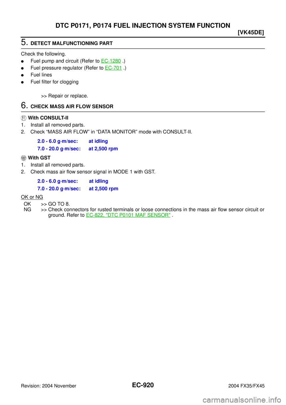
5. DETECT MALFUNCTIONING PART
Check the following.
�Fuel pump and circuit (Refer to EC-1280 .)
�Fuel pressure regulator (Refer to EC-701 .)
�Fuel lines
�Fuel filter for clogging
>> Repair or replace.
6. CHECK MASS AIR FLOW SENSOR
With CONSULT-II
1. Install all removed parts.
2. Check “MASS AIR FLOW” in “DATA MONITOR” mode with CONSULT-II.
With GST
1. Install all removed parts.
2. Check mass air flow sensor signal in MODE 1 with GST.
OK or NG
OK >> GO TO 8.
NG >> Check connectors for rusted terminals or loose connections in the mass air flow sensor circuit or
ground. Refer to EC-822, "
DTC P0101 MAF SENSOR" . 2.0 - 6.0 g·m/sec: at idling
7.0 - 20.0 g·m/sec: at 2,500 rpm
2.0 - 6.0 g·m/sec: at idling
7.0 - 20.0 g·m/sec: at 2,500 rpm
Page 2264 of 4449
![INFINITI FX35 2004 Service Manual DTC P0172, P0175 FUEL INJECTION SYSTEM FUNCTION
EC-923
[VK45DE]
C
D
E
F
G
H
I
J
K
L
MA
EC
Revision: 2004 November 2004 FX35/FX45
DTC P0172, P0175 FUEL INJECTION SYSTEM FUNCTIONPFP:16600
On Board Diagn](/manual-img/42/57021/w960_57021-2263.png "INFINITI FX35 2004 Service Manual DTC P0172, P0175 FUEL INJECTION SYSTEM FUNCTION
EC-923
[VK45DE]
C
D
E
F
G
H
I
J
K
L
MA
EC
Revision: 2004 November 2004 FX35/FX45
DTC P0172, P0175 FUEL INJECTION SYSTEM FUNCTIONPFP:16600
On Board Diagn")
DTC P0172, P0175 FUEL INJECTION SYSTEM FUNCTION
EC-923
[VK45DE]
C
D
E
F
G
H
I
J
K
L
MA
EC
Revision: 2004 November 2004 FX35/FX45
DTC P0172, P0175 FUEL INJECTION SYSTEM FUNCTIONPFP:16600
On Board Diagnosis LogicABS00C3Y
With the Air-Fuel Mixture Ratio Self-Learning Control, the actual mixture ratio can be brought closely to the
theoretical mixture ratio based on the mixture ratio feedback signal from the heated oxygen sensors 1. The
ECM calculates the necessary compensation to correct the offset between the actual and the theoretical
ratios.
In case the amount of the compensation value is extremely large (the actual mixture ratio is too rich.), the
ECM judges the condition as the fuel injection system malfunction and lights up the MIL (2 trip detection logic).
DTC Confirmation ProcedureABS00C3Z
NOTE:
If DTC Confirmation Procedure has been previously conducted, always turn ignition switch OFF and wait at
least 10 seconds before conducting the next test.
WITH CONSULT-II
1. Start engine and warm it up to normal operating temperature.
2. Turn ignition switch OFF and wait at least 10 seconds.
3. Turn ignition switch ON and select “SELF-LEARNING CONT” in “WORK SUPPORT” mode with CON-
SULT-II.
4. Clear the self-learning control coefficient by touching “CLEAR”.
5. Select “DATA MONITOR” mode with CONSULT-II.
6. Start engine again and let it idle for at least 10 minutes.
The 1st trip DTC P0172 or P0175 should be detected at this
stage, if a malfunction exists. If so, go to EC-927, "
Diagnostic
Procedure" .
7. If it is difficult to start engine at step 6, the fuel injection system
has a malfunction, too.
8. Crank engine while depressing accelerator pedal.
If engine starts, go to EC-927, "
Diagnostic Procedure" .
If engine does not start, remove ignition plugs and check for
fouling, etc.
Sensor Input signal to ECM ECM function Actuator
Heated oxygen sensor 1Density of oxygen in exhaust gas
(Mixture ratio feedback signal)Fuel injection
controlFuel injector
DTC No.Trouble diagnosis
nameDTC detecting condition Possible cause
P0172
0172
(Bank 1)
Fuel injection system
too rich
�Fuel injection system does not operate properly.
�The amount of mixture ratio compensation is too
large. (The mixture ratio is too rich.)
�Heated oxygen sensor 1
�Fuel injector
�Exhaust gas leaks
�Incorrect fuel pressure
�Mass air flow sensor P0175
0175
(Bank 2)
SEF968Y
Page 2265 of 4449
![INFINITI FX35 2004 Service Manual EC-924
[VK45DE]
DTC P0172, P0175 FUEL INJECTION SYSTEM FUNCTION
Revision: 2004 November 2004 FX35/FX45
WITH GST
1. Start engine and warm it up to normal operating temperature.
2. Turn ignition switch](/manual-img/42/57021/w960_57021-2264.png "INFINITI FX35 2004 Service Manual EC-924
[VK45DE]
DTC P0172, P0175 FUEL INJECTION SYSTEM FUNCTION
Revision: 2004 November 2004 FX35/FX45
WITH GST
1. Start engine and warm it up to normal operating temperature.
2. Turn ignition switch")
EC-924
[VK45DE]
DTC P0172, P0175 FUEL INJECTION SYSTEM FUNCTION
Revision: 2004 November 2004 FX35/FX45
WITH GST
1. Start engine and warm it up to normal operating temperature.
2. Turn ignition switch OFF and wait at least 10 seconds.
3. Disconnect mass air flow sensor harness connector. Then
restart and run engine for at least 5 seconds at idle speed.
4. Stop engine and reconnect mass air flow sensor harness con-
nector.
5. Select MODE 3 with GST. Make sure DTC P0102 is detected.
6. Select MODE 4 with GST and erase the DTC P0102.
7. Start engine again and let it idle for at least 10 minutes.
8. Select MODE 7 with GST. The 1st trip DTC P0172 or P0175
should be detected at this stage, if a malfunction exists. If so, go
to EC-927, "
Diagnostic Procedure" .
9. If it is difficult to start engine at step 7, the fuel injection system
has a malfunction.
10. Crank engine while depressing accelerator pedal.
If engine starts, go to EC-927, "
Diagnostic Procedure" . If engine does not start, remove ignition plugs and
check for fouling, etc.
PBIB1502E
Page 2268 of 4449
DTC P0172, P0175 FUEL INJECTION SYSTEM FUNCTION
EC-927
[VK45DE]
C
D
E
F
G
H
I
J
K
L
MA
EC
Revision: 2004 November 2004 FX35/FX45
Diagnostic ProcedureABS00C41
1. CHECK EXHAUST GAS LEAK
1. Start engine and run it at idle.
2. Listen for an exhaust gas leak before three way catalyst (manifold).
OK or NG
OK >> GO TO 2.
NG >> Repair or replace.
2. CHECK FOR INTAKE AIR LEAK
Listen for an intake air leak after the mass air flow sensor.
OK or NG
OK >> GO TO 3.
NG >> Repair or replace.
SEC502D
Page 2270 of 4449
DTC P0172, P0175 FUEL INJECTION SYSTEM FUNCTION
EC-929
[VK45DE]
C
D
E
F
G
H
I
J
K
L
MA
EC
Revision: 2004 November 2004 FX35/FX45
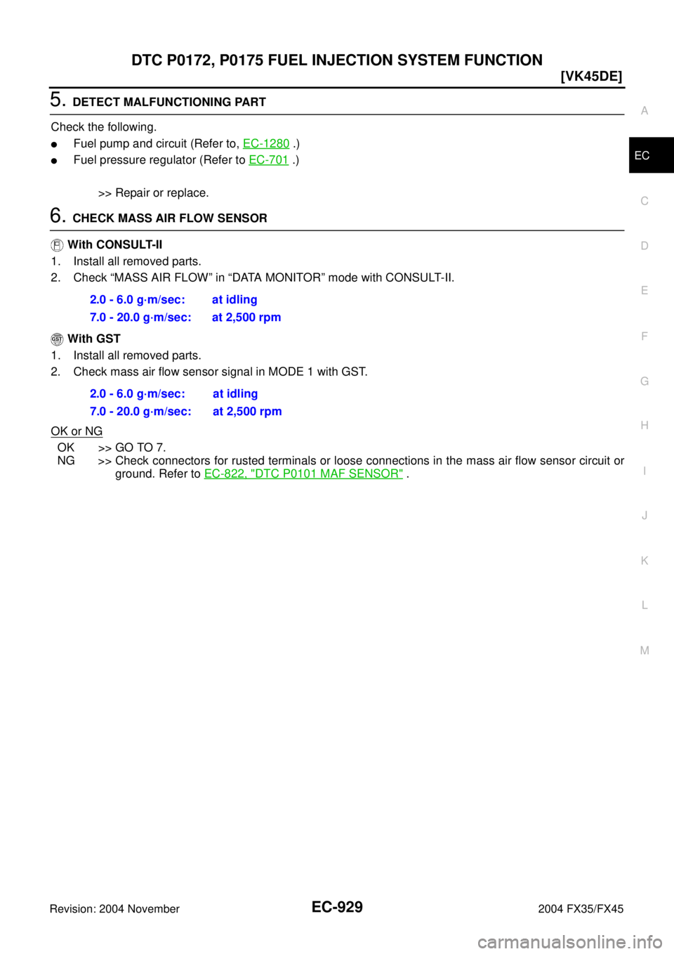
5. DETECT MALFUNCTIONING PART
Check the following.
�Fuel pump and circuit (Refer to, EC-1280 .)
�Fuel pressure regulator (Refer to EC-701 .)
>> Repair or replace.
6. CHECK MASS AIR FLOW SENSOR
With CONSULT-II
1. Install all removed parts.
2. Check “MASS AIR FLOW” in “DATA MONITOR” mode with CONSULT-II.
With GST
1. Install all removed parts.
2. Check mass air flow sensor signal in MODE 1 with GST.
OK or NG
OK >> GO TO 7.
NG >> Check connectors for rusted terminals or loose connections in the mass air flow sensor circuit or
ground. Refer to EC-822, "
DTC P0101 MAF SENSOR" . 2.0 - 6.0 g·m/sec: at idling
7.0 - 20.0 g·m/sec: at 2,500 rpm
2.0 - 6.0 g·m/sec: at idling
7.0 - 20.0 g·m/sec: at 2,500 rpm
Page 2294 of 4449
![INFINITI FX35 2004 Service Manual DTC P0300 - P0308 MULTIPLE CYLINDER MISFIRE, NO. 1 - 8 CYLINDER MIS-
FIRE
EC-953
[VK45DE]
C
D
E
F
G
H
I
J
K
L
MA
EC
Revision: 2004 November 2004 FX35/FX45
9. DETECT MALFUNCTIONING PART
Check the follo](/manual-img/42/57021/w960_57021-2293.png "INFINITI FX35 2004 Service Manual DTC P0300 - P0308 MULTIPLE CYLINDER MISFIRE, NO. 1 - 8 CYLINDER MIS-
FIRE
EC-953
[VK45DE]
C
D
E
F
G
H
I
J
K
L
MA
EC
Revision: 2004 November 2004 FX35/FX45
9. DETECT MALFUNCTIONING PART
Check the follo")
DTC P0300 - P0308 MULTIPLE CYLINDER MISFIRE, NO. 1 - 8 CYLINDER MIS-
FIRE
EC-953
[VK45DE]
C
D
E
F
G
H
I
J
K
L
MA
EC
Revision: 2004 November 2004 FX35/FX45
9. DETECT MALFUNCTIONING PART
Check the following.
�Fuel pump and circuit (Refer to EC-1280, "FUEL PUMP CIRCUIT" .)
�Fuel pressure regulator (Refer to EC-701, "FUEL PRESSURE CHECK" .)
�Fuel lines
�Fuel filter for clogging
>> Repair or replace.
10. CHECK IGNITION TIMING
Check the following items. Refer to EC-733, "
Basic Inspection" .
OK or NG
OK >> GO TO 11.
NG >> Follow the EC-733, "
Basic Inspection" .
11 . CHECK HEATED OXYGEN SENSOR 1 (BANK 1)/(BANK 2)
Refer to EC-870, "
Component Inspection" .
OK or NG
OK >> GO TO 12.
NG >> Replace (malfunctioning) heated oxygen sensor 1.
12. CHECK MASS AIR FLOW SENSOR
With CONSULT-II
Check mass air flow sensor signal in “DATA MONITOR” mode with CONSULT-II.
With GST
Check mass air flow sensor signal in MODE 1 with GST.
OK or NG
OK >> GO TO 13.
NG >> Check connectors for rusted terminals or loose connections in the mass air flow sensor circuit or
ground. Refer to EC-822, "
DTC P0101 MAF SENSOR" .
13. CHECK SYMPTOM MATRIX CHART
Check items on the rough idle symptom in EC-738, "
Symptom Matrix Chart" .
OK or NG
OK >> GO TO 14.
NG >> Repair or replace.
Items Specifications
Target idle speed 650 ± 50 rpm (in P or N position)
Ignition timing 12 ± 5° BTDC (in P or N position)
2.0 - 6.0 g·m/sec: at idling
7.0 - 20.0 g·m/sec: at 2,500 rpm
2.0 - 6.0 g·m/sec: at idling
7.0 - 20.0 g·m/sec: at 2,500 rpm
Page 2314 of 4449
![INFINITI FX35 2004 Service Manual DTC P0420, P0430 THREE WAY CATALYST FUNCTION
EC-973
[VK45DE]
C
D
E
F
G
H
I
J
K
L
MA
EC
Revision: 2004 November 2004 FX35/FX45
7. Make sure that the voltage switching frequency (high & low)
between ECM](/manual-img/42/57021/w960_57021-2313.png "INFINITI FX35 2004 Service Manual DTC P0420, P0430 THREE WAY CATALYST FUNCTION
EC-973
[VK45DE]
C
D
E
F
G
H
I
J
K
L
MA
EC
Revision: 2004 November 2004 FX35/FX45
7. Make sure that the voltage switching frequency (high & low)
between ECM")
DTC P0420, P0430 THREE WAY CATALYST FUNCTION
EC-973
[VK45DE]
C
D
E
F
G
H
I
J
K
L
MA
EC
Revision: 2004 November 2004 FX35/FX45
7. Make sure that the voltage switching frequency (high & low)
between ECM terminals 55 and ground, or 74 and ground is
very less than that of ECM terminals 16 and ground, or 35 and
ground.
Switching frequency ratio = A/B
A: Heated oxygen sensor 2 voltage switching frequency
B: Heated oxygen sensor 1 voltage switching frequency
This ratio should be less than 0.75.
If the ratio is greater than above, it means three way catalyst
(manifold) does not operate properly. Go to EC-973, "
Diagnostic
Procedure" .
NOTE:
If the voltage at terminal 16 or 35 does not switch periodically more than 5 times within 10 seconds at step 7,
perform trouble diagnosis for DTC P0133, P0153 first. (See EC-872
.)
Diagnostic ProcedureABS00C5G
1. CHECK EXHAUST SYSTEM
Visually check exhaust tubes and muffler for dent.
OK or NG
OK >> GO TO 2.
NG >> Repair or replace.
2. CHECK EXHAUST GAS LEAK
1. Start engine and run it at idle.
2. Listen for an exhaust gas leak before the three way catalyst (manifold).
OK or NG
OK >> GO TO 3.
NG >> Repair or replace.
3. CHECK INTAKE AIR LEAK
Listen for an intake air leak after the mass air flow sensor.
OK or NG
OK >> GO TO 4.
NG >> Repair or replace.
PBIB1529E
SEC502D
![INFINITI FX35 2004 Service Manual EC-918
[VK45DE]
DTC P0171, P0174 FUEL INJECTION SYSTEM FUNCTION
Revision: 2004 November 2004 FX35/FX45
Diagnostic ProcedureABS00C3X
1. CHECK EXHAUST GAS LEAK
1. Start engine and run it at idle.
2. Lis](/manual-img/42/57021/w960_57021-2258.png "INFINITI FX35 2004 Service Manual EC-918
[VK45DE]
DTC P0171, P0174 FUEL INJECTION SYSTEM FUNCTION
Revision: 2004 November 2004 FX35/FX45
Diagnostic ProcedureABS00C3X
1. CHECK EXHAUST GAS LEAK
1. Start engine and run it at idle.
2. Lis")
![INFINITI FX35 2004 Service Manual DTC P0172, P0175 FUEL INJECTION SYSTEM FUNCTION
EC-927
[VK45DE]
C
D
E
F
G
H
I
J
K
L
MA
EC
Revision: 2004 November 2004 FX35/FX45
Diagnostic ProcedureABS00C41
1. CHECK EXHAUST GAS LEAK
1. Start engine](/manual-img/42/57021/w960_57021-2267.png "INFINITI FX35 2004 Service Manual DTC P0172, P0175 FUEL INJECTION SYSTEM FUNCTION
EC-927
[VK45DE]
C
D
E
F
G
H
I
J
K
L
MA
EC
Revision: 2004 November 2004 FX35/FX45
Diagnostic ProcedureABS00C41
1. CHECK EXHAUST GAS LEAK
1. Start engine")