Page 3004 of 4449
EX-1
EXHAUST SYSTEM
B ENGINE
CONTENTS
C
D
E
F
G
H
I
J
K
L
M
SECTION EX
A
EX
Revision: 2004 November 2004 FX35/FX45
EXHAUST SYSTEM
PREPARATION ........................................................... 2
Commercial Service Tools ........................................ 2
EXHAUST SYSTEM ................................................... 3Checking Exhaust System ........................................ 3
Removal and Installation .......................................... 3
REMOVAL ............................................................. 4
INSTALLATION ..................................................... 4
INSPECTION AFTER INSTALLATION .................. 5
Page 3006 of 4449
EXHAUST SYSTEM
EX-3
C
D
E
F
G
H
I
J
K
L
MA
EX
Revision: 2004 November 2004 FX35/FX45
EXHAUST SYSTEMPFP:20100
Checking Exhaust SystemABS005Z5
Check exhaust pipes, muffler and mounting for improper attachment,
leaks, cracks, damage or deterioration.
�If anything is found, repair or replace damaged parts.
Removal and InstallationABS005Z6
CAUTION:
�Be sure to use genuine exhaust system parts or equivalents which are specially designed for heat
resistance, corrosion resistance, and shape.
�Perform the operation with the exhaust system fully cooled down because the system will be hot
just after engine stops.
�Be careful not to cut your hand on the heat insulator edge.
VQ35DE
SMA211A
PBIC1583E
1. Main muffler 2. Mounting rubber 3. Main muffler mounting bracket
4. Mounting rubber 5. Center muffler 6. Gasket
7. Exhaust front tube 8. Gasket 9. Collar
Page 3007 of 4449
EX-4
EXHAUST SYSTEM
Revision: 2004 November 2004 FX35/FX45
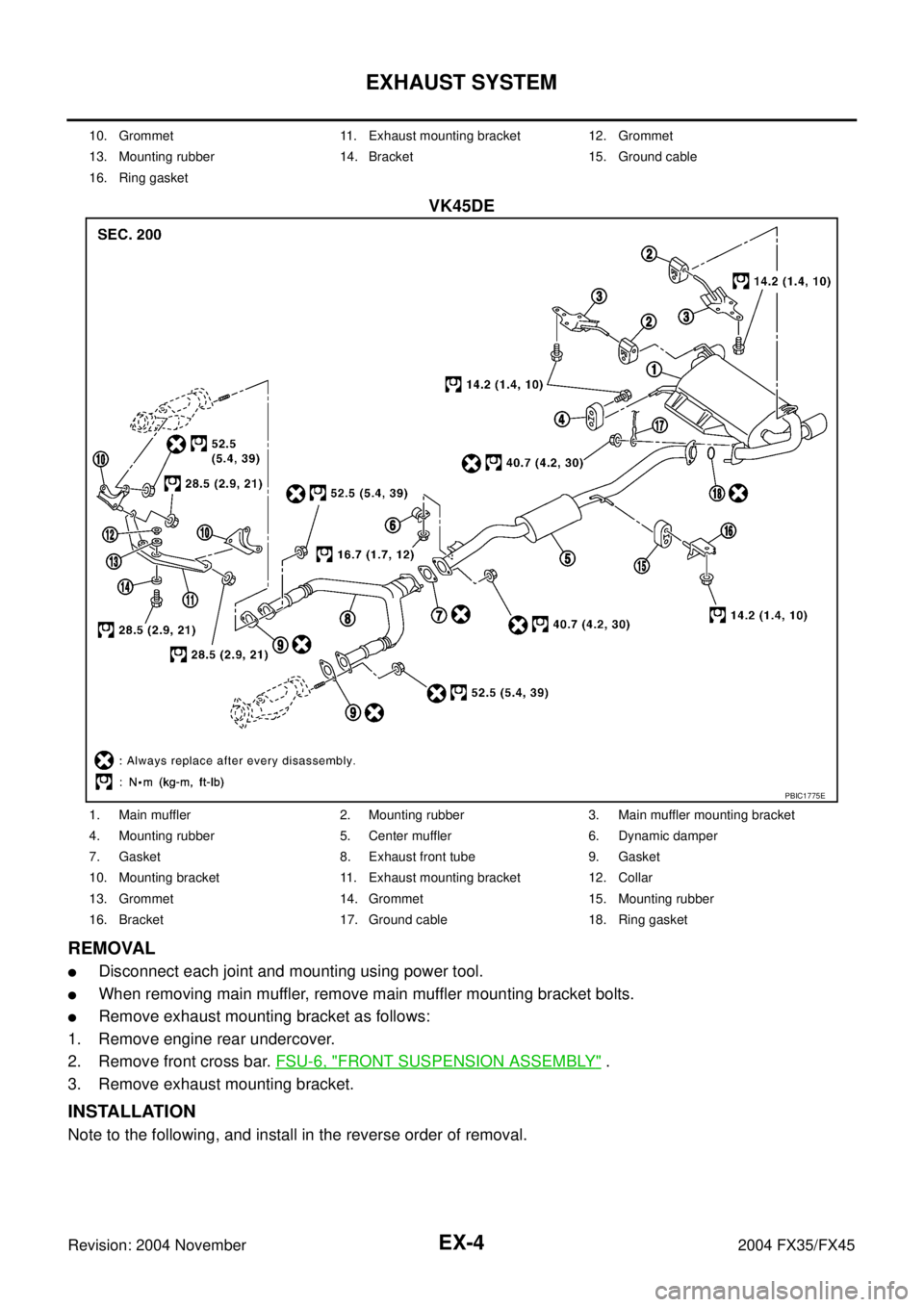
VK45DE
REMOVAL
�Disconnect each joint and mounting using power tool.
�When removing main muffler, remove main muffler mounting bracket bolts.
�Remove exhaust mounting bracket as follows:
1. Remove engine rear undercover.
2. Remove front cross bar. FSU-6, "
FRONT SUSPENSION ASSEMBLY" .
3. Remove exhaust mounting bracket.
INSTALLATION
Note to the following, and install in the reverse order of removal.
10. Grommet 11. Exhaust mounting bracket 12. Grommet
13. Mounting rubber 14. Bracket 15. Ground cable
16. Ring gasket
PBIC1775E
1. Main muffler 2. Mounting rubber 3. Main muffler mounting bracket
4. Mounting rubber 5. Center muffler 6. Dynamic damper
7. Gasket 8. Exhaust front tube 9. Gasket
10. Mounting bracket 11. Exhaust mounting bracket 12. Collar
13. Grommet 14. Grommet 15. Mounting rubber
16. Bracket 17. Ground cable 18. Ring gasket
Page 3008 of 4449

EXHAUST SYSTEM
EX-5
C
D
E
F
G
H
I
J
K
L
MA
EX
Revision: 2004 November 2004 FX35/FX45
�Tighten main muffler mounting bracket bolts in numerical order
as shown in the figure.
CAUTION:
�Always replace exhaust tube gaskets with new ones when reassembling.
�If heat insulator is badly deformed, repair or replace it. If deposits such as mud pile up on the heat
insulator, remove them.
�When installing heat insulator avoid large gaps or interference between heat insulator and each
exhaust pipe.
�Remove deposits from the sealing surface of each connection. Connect them securely to avoid
gas leakage.
�Temporarily tighten mounting nuts on the exhaust manifold side and mounting bolts on the vehi-
cle side. Check each part for unusual interference, and then tighten them to the specified torque.
�When installing each mounting rubber, avoid twisting or unusual extension in up/down and right/
left directions.
INSPECTION AFTER INSTALLATION
�Make sure clearance between tail tube and bumper is even.
�With engine running, check exhaust tube joints for gas leakage and unusual noises.
�Check to ensure that mounting brackets and mounting rubbers are installed properly and free from undue
stress. Improper installation could result in excessive noise and vibration.
PBIC1049E
Page 3009 of 4449
EX-6
EXHAUST SYSTEM
Revision: 2004 November 2004 FX35/FX45
Page 3083 of 4449

FL-10
FUEL TANK
Revision: 2004 November 2004 FX35/FX45
FUEL TANKPFP:17202
Removal and InstallationABS005Z1
REMOVAL
WARNING:
Be sure to read “General Precautions” when working on the fuel system. Refer to FL-3, "
General Pre-
cautions" .
�Drain fuel from fuel tank if necessary. Refer to FL-4, "REMOVAL" .
�Perform work on level place.
1. Perform steps 2 to 7 of “REMOVAL” in “ FUEL LEVEL SENSOR UNIT, FUEL FILTER AND FUEL PUMP
ASSEMBLY” on main and sub fuel level sensor units. Refer to FL-4, "
REMOVAL" .
2. Remove tunnel stay. Refer to RSU-5, "
REAR SUSPENSION ASSEMBLY" .
3. Remove exhaust front tube, center muffler and main muffler. Refer to EX-3, "
EXHAUST SYSTEM" .
4. Remove insulator.
5. Remove propeller shaft. Refer to PR-6, "
REAR PROPELLER SHAFT" .
6. Remove parking rear brake cables. Refer to PB-3, "
PARKING BRAKE CONTROL" .
7. Remove rear suspension assembly. Refer to RSU-5, "
REAR SUSPENSION ASSEMBLY" .
8. Remove fuel tank protector.
1. Grommet 2. Fuel filler cap 3. Clip
4. Fuel filler tube protector 5. Fuel tank mounting band 6. Fuel tank protector
7. Insulator 8. Fuel tank 9. Vent tube
10. Vent hose 11. EVAP hose 12. Vent hose
13. Fuel filler hose 14. Fuel filler tube
PBIC1580E
Page 3107 of 4449

GI-4
PRECAUTIONS
Revision: 2004 November 2004 FX35/FX45
Precautions Necessary for Steering Wheel Rotation After Battery DisconnectAAS000OH
NOTE:
�This Procedure is applied only to models with Intelligent Key system and NVIS/IVIS (NISSAN/INFINITI
VEHICLE IMMOBILIZER SYSTEM - NATS).
�Remove and install all control units after disconnecting both battery cables with the ignition knob in the
″LOCK″ position.
�Always use CONSULT-II to perform self-diagnosis as a part of each function inspection after finishing
work. If DTC is detected, perform trouble diagnosis according to self-diagnostic results.
For models equipped with the Intelligent Key system and NVIS/IVIS, an electrically controlled steering lock
mechanism is adopted on the key cylinder.
For this reason, if the battery is disconnected or if the battery is discharged, the steering wheel will lock and
steering wheel rotation will become impossible.
If steering wheel rotation is required when battery power is interrupted, follow the procedure below before
starting the repair operation.
OPERATION PROCEDURE
1. Connect both battery cables.
NOTE:
Supply power using jumper cables if battery is discharged.
2. Use the Intelligent Key or mechanical key to turn the ignition switch to the ″ACC″ position. At this time, the
steering lock will be released.
3. Disconnect both battery cables. The steering lock will remain released and the steering wheel can be
rotated.
4. Perform the necessary repair operation.
5. When the repair work is completed, return the ignition switch to the ″LOCK″ position before connecting
the battery cables. (At this time, the steering lock mechanism will engage.)
6. Perform a self-diagnosis check of all control units using CONSULT-II.
General PrecautionsAAS000EY
�Do not operate the engine for an extended period of time without
proper exhaust ventilation.
Keep the work area well ventilated and free of any inflammable
materials. Special care should be taken when handling any
inflammable or poisonous materials, such as gasoline, refriger-
ant gas, etc. When working in a pit or other enclosed area, be
sure to properly ventilate the area before working with hazard-
ous materials.
Do not smoke while working on the vehicle.
�Before jacking up the vehicle, apply wheel chocks or other tire
blocks to the wheels to prevent the vehicle from moving. After
jacking up the vehicle, support the vehicle weight with safety
stands at the points designated for proper lifting before working
on the vehicle.
These operations should be done on a level surface.
�When removing a heavy component such as the engine or tran-
saxle/transmission, be careful not to lose your balance and drop
them. Also, do not allow them to strike adjacent parts, especially
the brake tubes and master cylinder.
SGI285
SGI231
Page 3108 of 4449

PRECAUTIONS
GI-5
C
D
E
F
G
H
I
J
K
L
MB
GI
Revision: 2004 November 2004 FX35/FX45
�Before starting repairs which do not require battery power:
Turn off ignition switch.
Disconnect the negative battery terminal.
�If the battery terminals are disconnected, recorded memory of
radio and each control unit is erased.
�To prevent serious burns:
Avoid contact with hot metal parts.
Do not remove the radiator cap when the engine is hot.
�Dispose of drained oil or the solvent used for cleaning parts in
an appropriate manner.
�Do not attempt to top off the fuel tank after the fuel pump nozzle
shuts off automatically.
Continued refueling may cause fuel overflow, resulting in fuel
spray and possibly a fire.
�Clean all disassembled parts in the designated liquid or solvent
prior to inspection or assembly.
�Replace oil seals, gaskets, packings, O-rings, locking washers, cotter pins, self-locking nuts, etc. with new
ones.
�Replace inner and outer races of tapered roller bearings and needle bearings as a set.
�Arrange the disassembled parts in accordance with their assembled locations and sequence.
�Do not touch the terminals of electrical components which use microcomputers (such as ECM).
Static electricity may damage internal electronic components.
�After disconnecting vacuum or air hoses, attach a tag to indicate the proper connection.
�Use only the fluids and lubricants specified in this manual.
�Use approved bonding agent, sealants or their equivalents when required.
�Use hand tools, power tools (disassembly only) and recom-
mended special tools where specified for safe and efficient ser-
vice repairs.
�When repairing the fuel, oil, water, vacuum or exhaust systems,
check all affected lines for leaks.
�Before servicing the vehicle:
Protect fenders, upholstery and carpeting with appropriate cov-
ers.
Take caution that keys, buckles or buttons do not scratch paint.
SEF289H
SGI233
PBIC0190E
SGI234