2004 Hyundai Santa Fe air
[x] Cancel search: airPage 213 of 253

6DO-IT-YOURSELF MAINTENANCE
19CHECKING THE FREE-PLAY
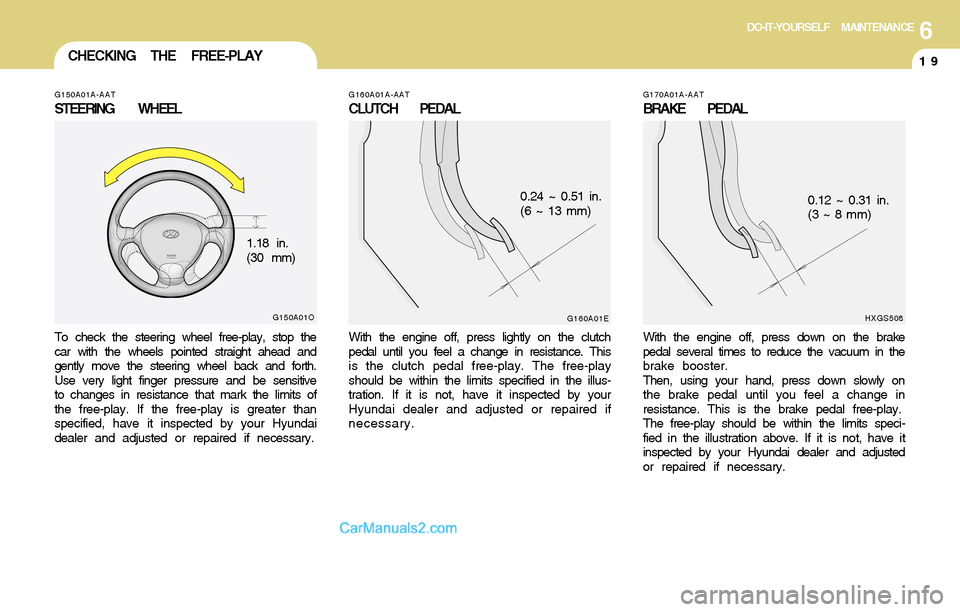
G160A01A-AAT
CLUTCH PEDAL
With the engine off, press lightly on the clutch
pedal until you feel a change in resistance. This
is the clutch pedal free-play. The free-play
should be within the limits specified in the illus-
tration. If it is not, have it inspected by your
Hyundai dealer and adjusted or repaired if
necessary.
G160A01E
0.24 ~ 0.51 in.
(6 ~ 13 mm)
G170A01A-AAT
BRAKE PEDAL
With the engine off, press down on the brake
pedal several times to reduce the vacuum in the
brake booster.
Then, using your hand, press down slowly on
the brake pedal until you feel a change in
resistance. This is the brake pedal free-play.
The free-play should be within the limits speci-
fied in the illustration above. If it is not, have it
inspected by your Hyundai dealer and adjusted
or repaired if necessary.
HXGS508
0.12 ~ 0.31 in.
(3 ~ 8 mm)
G150A01A-AAT
STEERING WHEEL
To check the steering wheel free-play, stop the
car with the wheels pointed straight ahead and
gently move the steering wheel back and forth.
Use very light finger pressure and be sensitive
to changes in resistance that mark the limits of
the free-play. If the free-play is greater than
specified, have it inspected by your Hyundai
dealer and adjusted or repaired if necessary.
G150A01O
1.18 in.
(30 mm)
Page 214 of 253

6DO-IT-YOURSELF MAINTENANCE
20CHECKING BRAKE PEDAL
CLEARANCECHECKING DRIVE BELTS
G180A01A-AAT
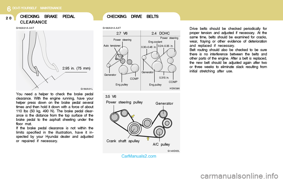
You need a helper to check the brake pedal
clearance. With the engine running, have your
helper press down on the brake pedal several
times and then hold it down with a force of about
110 lbs (50 kg, 490 N). The brake pedal clear-
ance is the distance from the top surface of the
brake pedal to the asphalt sheeting under the
floor mat.
If the brake pedal clearance is not within the
limits specified in the illustration, have it in-
spected by your Hyundai dealer and adjusted
or repaired if necessary.
G180A01L
2.95 in. (75 mm)Drive belts should be checked periodically for
proper tension and adjusted if necessary. At the
same time, belts should be examined for cracks,
wear, fraying or other evidence of deterioration
and replaced if necessary.
Belt routing should also be checked to be sure
there is no interference between the belts and
other parts of the engine. After a belt is replaced,
the new belt should be adjusted again after two
or three weeks to eliminate slack resulting from
initial stretching after use.
G190A01A-AAT
HSM396
2.7 V6 2.4 DOHC
COMP
Eng.pulleyEng.pulleyCOMP
0.315 in.
Power steeringPower steering
Auto tensioner
GeneratorGeneratorEng.coolant
0.30~0.48 in.0.24~0.35 in.
G140D02L
3.5 V6
Crank shaft apulley
A/C pulley Power steering pulley
Generator
Page 215 of 253

6DO-IT-YOURSELF MAINTENANCE
21CHECKING AND REPLACING
FUSES
!
G200B01A-AATReplacing Accessory FusesCAUTION:
When replacing a fusible link, never use
anything but a new fusible link with the
same or lower amperage rating. Never use
a piece of wire or a higher-rated fusible link.
This could result in serious damage and
create a fire hazard.
The fuse box for the lights and other electrical
accessories will be found low on the dashboard
on the driver's side. Inside the box you will find
a list showing the circuits protected by each
fuse.
HSM391
If any of your car's lights or other electrical
accessories stop working, a blown (open) fuse
could be the reason. If the fuse has opened, you
will see that the metal strip inside the fuse has
melted through. If you suspect a blown fuse,
follow this procedure:
1 . Turn off the ignition and all other switches.
2 . Open the fuse box and examine each fuse.
Remove each fuse by pulling it toward you
(a small "fuse puller" tool is contained in the
fuse box to simplify this operation).
3 . Be sure to check all other fuses even if you
find one that appears to have opened.
HSM390
G200A02A-AAT
Replacing a Fusible Link
A fusible link will melt if the electrical circuits from
the battery are ever overloaded, thus prevent-
ing damage to the entire wiring harness. (This
could be caused by a short in the system
drawing too much current.) If this ever happens,
have a Hyundai dealer determine the cause,
repair the system and replace the fusible link.
The fusible links are located in a relay box for
easy inspection.
G200A01L
GoodOpen-
Replace
Page 216 of 253

6DO-IT-YOURSELF MAINTENANCE
22CHECKING THE BATTERY
!
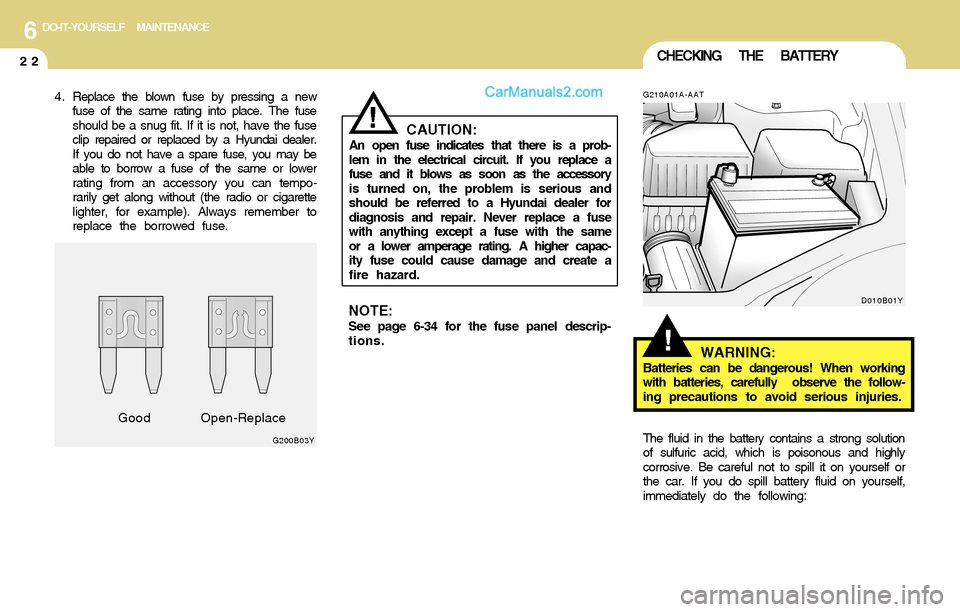
4 . Replace the blown fuse by pressing a new
fuse of the same rating into place. The fuse
should be a snug fit. If it is not, have the fuse
clip repaired or replaced by a Hyundai dealer.
If you do not have a spare fuse, you may be
able to borrow a fuse of the same or lower
rating from an accessory you can tempo-
rarily get along without (the radio or cigarette
lighter, for example). Always remember to
replace the borrowed fuse.
CAUTION:An open fuse indicates that there is a prob-
lem in the electrical circuit. If you replace a
fuse and it blows as soon as the accessory
is turned on, the problem is serious and
should be referred to a Hyundai dealer for
diagnosis and repair. Never replace a fuse
with anything except a fuse with the same
or a lower amperage rating. A higher capac-
ity fuse could cause damage and create a
fire hazard.
G200B03Y
GoodOpen-Replace
!
G210A01A-AAT
WARNING:Batteries can be dangerous! When working
with batteries, carefully observe the follow-
ing precautions to avoid serious injuries.
The fluid in the battery contains a strong solution
of sulfuric acid, which is poisonous and highly
corrosive. Be careful not to spill it on yourself or
the car. If you do spill battery fluid on yourself,
immediately do the following:
D010B01YNOTE:See page 6-34 for the fuse panel descrip-
tions.
Page 218 of 253

6DO-IT-YOURSELF MAINTENANCE
24POWER STEERING FLUID LEVEL
G230A03A-AAT
G220C01A-AAT
Checking Condenser Cooling Fan
The condenser cooling fan should come on
automatically whenever the air conditioning is in
operation.
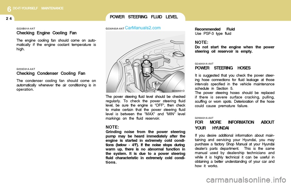
The power steering fluid level should be checked
regularly. To check the power steering fluid
level, be sure the engine is "OFF", then check
to make certain that the power steering fluid
level is between the "MAX" and "MIN" level
markings on the fluid reservoir.
NOTE:Grinding noise from the power steering
pump may be heard immediately after the
engine is started in extremely cold condi-
tions (below - 4°F). If the noise stops during
warm up, there is no abnormal function in
the system. It is due to a power steering
fluid characteristic in extremely cold condi-
tions.
G230A01O
G250A01A-AAT
FOR MORE INFORMATION ABOUT
YOUR HYUNDAI
If you desire additional information about main-
taining and servicing your Hyundai, you may
purchase a factory Shop Manual at your Hyundai
dealer's parts department. This is the same
manual used by dealership technicians and
while it is highly technical it can be useful in
obtaining a better understanding of your car and
how it works.
G240A01A-AAT
POWER STEERING HOSES
It is suggested that you check the power steer-
ing hose connections for fluid leakage at those
intervals specified in the vehicle maintenance
schedule in Section 5.
The power steering hoses should be replaced
if there is severe surface cracking, pulling,
scuffing or worn spots. Deterioration of the hose
could cause premature failure. Recommended Fluid
Use PSF-3 type fluid
NOTE:Do not start the engine when the power
steering oil reservoir is empty.
G220B01A-AAT
Checking Engine Cooling Fan
The engine cooling fan should come on auto-
matically if the engine coolant temperature is
high.
Page 219 of 253

6DO-IT-YOURSELF MAINTENANCE
25HEADLIGHT AIMING ADJUSTMENT
G290B01O-AAT
Adjustment After Headlight Assembly
Replacement
If the vehicle has had front body repair and the
headlight assembly has been replaced, the
headlight aiming should be checked using an
aiming chart as shown in the illustration. Turn on
the headlight switch. (Low Beam Position)
1 . Adjust headlights so that main axis of light is
parallel to center line of the body and is
aligned with point "P" shown in the illustration.
2 . Dotted lines in the illustration show the center
of headlights.
G290A03O
L
W
H
H
Cut-off line
Ground line
"P"
Horizontal line
Vertical line
!
6 . Draw the vertical line (through the center of
each headlight beam pattern) and the hori-
zontal line (through the center of each head-
light beam pattern) on the aiming screen.
And then, draw a parallel line at 0.8 in. (21
mm) under the horizontal line.
7. Adjust each cut-off line of the low beam to the
parallel line with a phillips screwdriver -
VERTICAL AIMING.
WARNING:Horizontal aiming should be adjusted by
an authorized Hyundai dealer.
G290A01O
Vertical
aiming
G290A02O-AAT
Before performing aiming adjustment, make
sure of the following.
1 . Keep all tires inflated to the correct pressure.
2 . Place the vehicle on level ground and press
the front bumper & rear bumper down sev-
eral times.
Place vehicle at a distance of 118 in. (3m)
from the test wall.
3 . See that the vehicle is unloaded (except for
full levels of coolant, engine oil and fuel, and
spare tire, jack, and tools). Have the driver
or equivalent weight placed in driver's seat.
4 . Clean the head light lenses and turn on the
headlights (Low beam).
5 . Open the hood.
Page 228 of 253

6DO-IT-YOURSELF MAINTENANCE
34FUSE PANEL DESCRIPTION
G200C01O-AAT
Engine Compartment
G200C01O-ANOTE:Not all fuse panel descriptions in this manual may be applicable to your vehicle. It is accurate at the time of printing. When you inspect the
fuse box on your vehicle, refer to the fuse box label.FUSE
RATING
120A
50A
50A
40A
30A
30A
40A
30A
40A
20A
15A
10A
10A
20A
20A
10A
15A
20A
10A
10A
10APROTECTED COMPONENTS
Generator
Tail lamp relay, Fuse 11~17, Power connector
Start relay, Ignition switch
A/C Fuse, Blower relay
ABS control module, Air bleeding connector
ABS control module, Air bleeding connector
Engine contorl relay
Power window relay, Fuse 26
Radiator fan relay
Condenser fan relay
Fog lamp relay
Left head lamp, Instrument cluster, DRL control module
Right head lamp
Ignition failure sensor, Oxygen sensor
Injector
Check engine ind, ECM, PCM
Fuel pump relay, ECM, TCM, Generator, PCM
ATM contorl relay, 4WD control module
Horn relay
A/C relay
PCM, ECM
ALT
B+
IGN
BLR
ABS.1
ABS.2
ECU
P/W
RAD FAN
C/FAN
FRT FOG
H/LP(LH)
H/LP(RH)
ECU #1
ECU #2
ECU #3
ECU(B+)
ATM
HORN
A/C
ST SIG FUSIBLE
LINK
FUSE
DESCRIPTION
Page 229 of 253

6DO-IT-YOURSELF MAINTENANCE
35
G200E01O-AAT
Inner Panel
G200E01O-A
PROTECTED COMPONENTS
Cigarette lighter & Power outlet
Audio, Power outside mirror
Digital clock, Rear power outlet
Cruise control
Head lamp relay
Seat warmer
Rear wiper motor control
Rear window defogger, Power outside mirror
A/C control, Sunroof controller, Electrical chrome mirror
(Not used)
Room lamp, Door warning switch, Door lamp, Manual A/C control, Homelink controller
Digatal clock, ETACM, Audio, Siren
AMP speakers
Stop lamp, Data link connector, Multipurpose check connector
Hazard lamp
Power seat, Rear wiper motor control
Sunroof controller
Defogger relay
Instrument cluster, Pre-excitation resistor, ETACM, Auto light sensor,
DRL control module, Generator
SRS control module
ECM (V6 2.7L), PCM (I4 with A/T), ECM (I4 with M/T)
Instrument cluster (Air bag IND)
ABS control module, G-Sensor, Air bledding connector, 4WD control module
Turn signal lamp
Back-up lamps, TCM, Vehicle speed secsor, ETS control module, Ignition failure sensor
Door lock/unlock relay, Key lock/unlock relay
Tail & parking lamp (LH), Turn signal lamp, License lamp
Tail & parking lamp (RH), Fog lamp relay, Switch illumination
ETS control module (V6 3.5L), Fail safety relay
Radiator fan relay, Condenser fan relay
Front wiper motor, Wiper relay, Washer motorFUSE
RATING
20A
10A
15A
10A
10A
25A
10A
10A
10A
10A
10A
15A
20A
10A
10A
25A
20A
30A
10A
15A
10A
10A
10A
10A
10A
20A
10A
10A
15A
10A
20A FUSE
F1
F2
F3
F4
F5
F6
F7
F8
F9
F10
F11
F12
F13
F14
F15
F16
F17
F18
F19
F20
F21
F22
F23
F24
F25
F26
F27
F28
F29
F30
F31