2004 Hyundai Santa Fe instrument panel
[x] Cancel search: instrument panelPage 55 of 253

1FEATURES OF YOUR HYUNDAI
42WARNING AND INDICATOR LIGHTS
B260B01A-AAT
SRS (Airbag) Service
Reminder Indicator (SRI)
The SRS service reminder indicator (SRI) comes
on and flashes for about 6 seconds after the
ignition key is turned to the "ON" position or after
the engine is started, after which it will go out.
This light also comes on when the SRS is not
working properly. If the SRI does not come on,
or continuously remains on after flashing for
about 6 seconds when you turned the ignition
key to the "ON" position or started the engine,
or if it comes on while driving, have the SRS
inspected by an authorized Hyundai Dealer.
B260D01A-AAT
Turn Signal Indicator Lights
The blinking green arrows on the instrument
panel show the direction indicated by the turn
signals. If the arrow comes on but does not blink,
blinks more rapidly than normal, or does not
illuminate at all, a malfunction in the turn signal
system is indicated. Your dealer should be
consulted for repairs.
B260E02O-AAT
Seat Belt Reminder Light
and Chime
The seat belt reminder light blinks until your seat
belt is fastened when the ignition key is turned
from the "OFF" position to "ON" or "START" and
the warning chime will sound for 6 seconds.
B260F01A-AAT
High Beam Indicator Light
The high beam indicator light comes on when-
ever the headlights are switched to the high
beam or flash position.
B260G01A-AAT
Low Oil Pressure Warning Light
CAUTION:
If the low oil pressure warning light stays on
while the engine is running, serious engine
damage may result. The oil pressure warn-
ing light comes on whenever there is insuf-
ficient oil pressure. In normal operation, it
should come on when the ignition switch
is turned on, then go out when the engine
is started. If the oil pressure warning light
stays on while the engine is running, there
is a serious malfunction.
If this happens, stop the car as soon as it is
safe to do so, turn off the engine and check
the oil level. If the oil level is low, fill the
engine oil to the proper level and start the
engine again. If the light stays on with the
engine running, turn the engine off imme-
diately. In any instance where the oil light
stays on when the engine is running, the
engine should be checked by a Hyundai
dealer before the car is driven again.
!
Page 62 of 253

1FEATURES OF YOUR HYUNDAI
49
B340D01A-AAT
High-beam Switch
To turn on the headlight high beams, push the
lever forward (away from you). The High Beam
Indicator Light will come on at the same time. For
low beams, pull the lever back toward you.
B340E01A-AATHeadlight Flasher
To flash the headlights, pull the switch lever
toward you, then release it. The headlights can
be flashed even though the headlight switch is
in the "OFF" position.
B340E01O
B340B01A-AAT
Lane Change Signal
To indicate a lane change, move the lever up or
down to a point where it begins flashing.
The lever will automatically return to the center
position when released.
B340C03A-AAT
Headlight Switch
To operate the headlights, turn the barrel on the
end of the multi-function switch. The first posi-
tion turns on the parking lights, sidelights, tail
lights and instrument panel lights. The second
position turns on the headlights.
NOTE:The ignition must be in the "ON" position
to turn on the headlights.
Parking Light Auto Off
If you do not turn the parking lights "OFF" after
driving, the parking lights will automatically shut
"OFF" when the driver's door is opened.
To turn them "ON" again, you must simply turn
the ignition key to the "ON" position.
HSM039HSM037
RIGHT
LEFT
Page 67 of 253
1FEATURES OF YOUR HYUNDAI
54POWER OUTLET
B500D08O-AAT
(If installed)
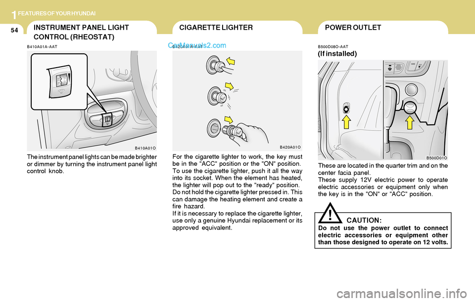
These are located in the quarter trim and on the
center facia panel.
These supply 12V electric power to operate
electric accessories or equipment only when
the key is in the "ON" or "ACC" position.
!CAUTION:Do not use the power outlet to connect
electric accessories or equipment other
than those designed to operate on 12 volts.
B500D01O
CIGARETTE LIGHTERINSTRUMENT PANEL LIGHT
CONTROL (RHEOSTAT)
B420A01A-AAT
For the cigarette lighter to work, the key must
be in the "ACC" position or the "ON" position.
To use the cigarette lighter, push it all the way
into its socket. When the element has heated,
the lighter will pop out to the "ready" position.
Do not hold the cigarette lighter pressed in. This
can damage the heating element and create a
fire hazard.
If it is necessary to replace the cigarette lighter,
use only a genuine Hyundai replacement or its
approved equivalent.
B420A01O
B410A01A-AAT
The instrument panel lights can be made brighter
or dimmer by turning the instrument panel light
control knob.
B410A01O
Page 102 of 253

1FEATURES OF YOUR HYUNDAI
89
B970C01O-GAT
Automatic OperationNOTE:If the battery has been discharged or dis-
connected, the temperature mode will reset
to Fahrenheit degree.
This is a normal condition and you can
adjust the temperature mode from Fahren-
heit to Centigrade as follows;
Press the TEMP down ( ) button 3 seconds
or more with the AMB button held down.
The display shows that the unit of tempera-
ture is adjusted to Fahrenheit or Centigrade
(°F
→ →→ →
→ °C or °C
→ →→ →
→ °F).
The FATC (Full Automatic Temperature Con-
trol) system automatically controls the heating
and cooling by doing as follows:
1. Push the "AUTO" switch. The indicator light
will come on confirming that the Face, Floor
and/or Bi-Level modes as well as the blower
speed and, the air conditioning will operate if
ambient temperature is higher than 32°F
(0°C) and automatically turns off if the ambi-
ent temperature drops below 32°F(0°C).
NOTE:Never place things on the sensor which is
located in the car on the instrument panel
to ensure better control of the heating and
cooling system.
B970C01O
HSM502
Photo sensor 2. Push the "TEMP" button to set the desired
temperature.
The temperature will increase to the maxi-
mum "HI" by pushing on the button. Each
push of the button will cause the temperature
to increase by 1°F(0.5°C).
The temperature will decrease to the mini-
mum "LO" by pushing on the button. Each
push of the button will cause the temperature
to decrease by 1°F(0.5°C).
B970C03O
Page 228 of 253

6DO-IT-YOURSELF MAINTENANCE
34FUSE PANEL DESCRIPTION
G200C01O-AAT
Engine Compartment
G200C01O-ANOTE:Not all fuse panel descriptions in this manual may be applicable to your vehicle. It is accurate at the time of printing. When you inspect the
fuse box on your vehicle, refer to the fuse box label.FUSE
RATING
120A
50A
50A
40A
30A
30A
40A
30A
40A
20A
15A
10A
10A
20A
20A
10A
15A
20A
10A
10A
10APROTECTED COMPONENTS
Generator
Tail lamp relay, Fuse 11~17, Power connector
Start relay, Ignition switch
A/C Fuse, Blower relay
ABS control module, Air bleeding connector
ABS control module, Air bleeding connector
Engine contorl relay
Power window relay, Fuse 26
Radiator fan relay
Condenser fan relay
Fog lamp relay
Left head lamp, Instrument cluster, DRL control module
Right head lamp
Ignition failure sensor, Oxygen sensor
Injector
Check engine ind, ECM, PCM
Fuel pump relay, ECM, TCM, Generator, PCM
ATM contorl relay, 4WD control module
Horn relay
A/C relay
PCM, ECM
ALT
B+
IGN
BLR
ABS.1
ABS.2
ECU
P/W
RAD FAN
C/FAN
FRT FOG
H/LP(LH)
H/LP(RH)
ECU #1
ECU #2
ECU #3
ECU(B+)
ATM
HORN
A/C
ST SIG FUSIBLE
LINK
FUSE
DESCRIPTION
Page 229 of 253

6DO-IT-YOURSELF MAINTENANCE
35
G200E01O-AAT
Inner Panel
G200E01O-A
PROTECTED COMPONENTS
Cigarette lighter & Power outlet
Audio, Power outside mirror
Digital clock, Rear power outlet
Cruise control
Head lamp relay
Seat warmer
Rear wiper motor control
Rear window defogger, Power outside mirror
A/C control, Sunroof controller, Electrical chrome mirror
(Not used)
Room lamp, Door warning switch, Door lamp, Manual A/C control, Homelink controller
Digatal clock, ETACM, Audio, Siren
AMP speakers
Stop lamp, Data link connector, Multipurpose check connector
Hazard lamp
Power seat, Rear wiper motor control
Sunroof controller
Defogger relay
Instrument cluster, Pre-excitation resistor, ETACM, Auto light sensor,
DRL control module, Generator
SRS control module
ECM (V6 2.7L), PCM (I4 with A/T), ECM (I4 with M/T)
Instrument cluster (Air bag IND)
ABS control module, G-Sensor, Air bledding connector, 4WD control module
Turn signal lamp
Back-up lamps, TCM, Vehicle speed secsor, ETS control module, Ignition failure sensor
Door lock/unlock relay, Key lock/unlock relay
Tail & parking lamp (LH), Turn signal lamp, License lamp
Tail & parking lamp (RH), Fog lamp relay, Switch illumination
ETS control module (V6 3.5L), Fail safety relay
Radiator fan relay, Condenser fan relay
Front wiper motor, Wiper relay, Washer motorFUSE
RATING
20A
10A
15A
10A
10A
25A
10A
10A
10A
10A
10A
15A
20A
10A
10A
25A
20A
30A
10A
15A
10A
10A
10A
10A
10A
20A
10A
10A
15A
10A
20A FUSE
F1
F2
F3
F4
F5
F6
F7
F8
F9
F10
F11
F12
F13
F14
F15
F16
F17
F18
F19
F20
F21
F22
F23
F24
F25
F26
F27
F28
F29
F30
F31
Page 235 of 253
8CONSUMER INFORMATION & REPORTING SAFETY DEFECTS
2TIREENGINE NUMBERVEHICLE IDENTIFICATION
NUMBER (VIN)
I030A02S-AAT
RECOMMENDED INFLATION PRES-
SURES
I020A01A-AAT
TIRE INFORMATION
The tires supplied on your new Hyundai are
chosen to provide the best performance for
normal driving.
I010B01A-AAT I010A02A-AAT
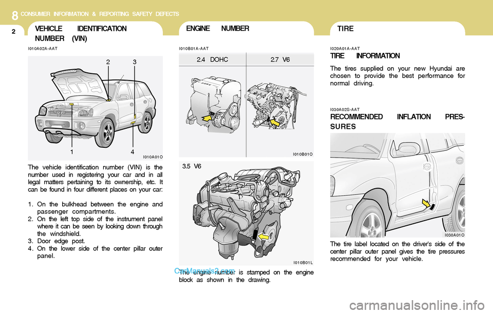
The vehicle identification number (VIN) is the
number used in registering your car and in all
legal matters pertaining to its ownership, etc. It
can be found in four different places on your car:
1. On the bulkhead between the engine and
passenger compartments.
2 . On the left top side of the instrument panel
where it can be seen by looking down through
the windshield.
3. Door edge post.
4 . On the lower side of the center pillar outer
panel.
The engine number is stamped on the engine
block as shown in the drawing.The tire label located on the driver's side of the
center pillar outer panel gives the tire pressures
recommended for your vehicle.
I010A01O
I030A01O I010B01O
2.4 DOHC2.7 V6
I010B01L
3.5 V6
23
14
Page 250 of 253

10INDEX
4
H
Hazard Warning System ..................................................................1-52
Heating and Cooling Control .............................................................1-78
Heating and Ventilation
Air flow control ..............................................................................1-80
Air intake control switch ...............................................................1-79
Bi-level heating .............................................................................1-84
Defrosting / Defogging .................................................................1-87
Fan speed control (Blower control) .............................................1-79
Temperature control ....................................................................1-83
High-Mounted Rear Stop Light .........................................................1-71
Homelink Mirror .................................................................................1-64
Hood Release ....................................................................................1-72
Horn.................................................................................................1-75
I
Ignition Switch ...................................................................................... 2-4
Instrument Cluster and Indicator Lights ................................. 1-38, 1-40
Instrument Panel Light Control (Rheostat) .......................................1-54
Interior Light .......................................................................................1-59
J
Jump Starting ...................................................................................... 3-2
K
Keys................................................................................................... 1-3
If you lose your keys ...................................................................3-13
Positions......................................................................................... 2-4L
Light Bulbs Replacement ..................................................................6-26
Limited-Slip Differential ......................................................................2-20
Luggage Compartment Light ............................................................1-68
Luggage Net ......................................................................................1-69
M
Maintenance Intervals
Explanation of scheduled maintenance items ............................... 5-7
Maintenance under severe usage conditions ............................... 5-6
Scheduled maintenance ................................................................ 5-4
Service requirements .................................................................... 5-2
Mirrors
Day-night inside rearview mirror .................................................1-63
Outside rearview mirror ...............................................................1-61
O
Odometer / Trip Odometer ...............................................................1-47
P
Parking Brake ....................................................................................1-67
Power Driver's Seat ..........................................................................1-14
Power Outlet ......................................................................................1-54
Power Steering Fluid Level ...............................................................6-24