Page 173 of 273

4
Tools and Jack ............................................................. 4-2
Spare Tire ..................................................................... 4-3
If You Have a Flat Tire ................................................. 4-6
Changing a Flat Tire ..................................................... 4-7Towing........................................................................ 4-13
Bleeding the Fuel System .......................................... 4-18
Removal of Water from the Fuel Filter ....................... 4-19
If the Engine Will Not Start ......................................... 4-20
Jump Starting ............................................................. 4-21
If the Engine Overheats ............................................. 4-22
Checking and Replacing Fuses ................................. 4-24
Headlight Aiming Adjustment ..................................... 4-26
Replacement of Light Bulbs ....................................... 4-27
Bulb Wattage .............................................................. 4-35
Fuse Panel Description .............................................. 4-37
IN CASE OF EMERGENCY
4
Page 198 of 273

44IN CASE OF EMERGENCY
26
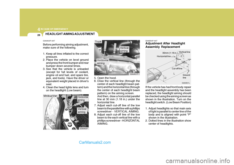
G290B03P-AAT Adjustment After Headlight Assembly Replacement If the vehicle has had front body repair and the headlight assembly has been replaced, the headlight aiming should be checked using the aiming screen asshown in the illustration. Turn on the headlight switch. (Low Beam Position)
1. Adjust headlights so that main axis
of light is parallel to center line of the body and is aligned with point "P"shown in the illustration.
2. Dotted lines in the illustration show
center of headlights.
5. Open the hood.
6. Draw the vertical line (through the
center of each headlight beam pat- tern) and the horizontal line (through the center of each headlight beam pattern) on the aiming screen.And then, draw a horizontal parallel line at 30 mm (1.18 in.) under the horizontal line.
7. Adjust each cut-off line of the low beam to the parallel line with a phillipsscrewdriver - VERTICAL AIMING.
8. Adjust each cut-off line of the low beam to the each vertical line with aphillips screwdriver - HORIZONTALAIMING.
Horizontal aiming
Verticalaiming
G290A01P-1
Truck
G290B01L
LW
H
H Cut-off line
Ground line
"P"
Horizontal line
30mm (1.18 in.) Vertical line
HEADLIGHT AIMING ADJUSTMENT
G290A03P-AAT Before performing aiming adjustment, make sure of the following.
1. Keep all tires inflated to the correct pressure.
2. Place the vehicle on level ground
and press the front bumper and rear bumper down several times.
3. See that the vehicle is unloaded
(except for full levels of coolant,engine oil and fuel, and spare tire, jack, and tools). Have the driver or equivalent weight placed in driver'sseat.
4. Clean the head lights lens and turn
on the headlight (Low beam).
Minibus/Van
G290A02P
Horizontal aiming
Verticalaiming
Page 199 of 273

4
CORROSION PREVENTION AND APPEARANCE CARE
27
4
IN CASE OF EMERGENCY
27
Specifications: "H": Horizontal center line of headlights from ground "W":Distance between each headlight cen-ter "L": Distance between the headlights and the wall that the lights are tested against : 3,000 mm (118.11 in.).
2WD 4WD
Long wheel base
Extra long
wheel base
MINIBUS 894
(35.20) 1006
(39.61)
- - VAN
855
(33.66)
--- TRUCK
--
847
(33.35) 845
(33.27)2WD 4WD
Long wheel base
Extra long
wheel base
MINIBUS
- - VAN
-- TRUCK
--
1272
(50.08)
1380
(54.33)
REPLACEMENT OF LIGHT BULBS
G260A03A-AAT Before attempting to replace a head- light bulb, be sure the switch is turned to the "OFF" position. The next paragraph shows how toreach the headlight bulbs so they may be changed. Be sure to replace the burned-out bulb with one of the samenumber and wattage rating. See page 4-35 for the wattage descrip- tions.
CAUTION:
Keep the lamps out of contact withpetroleum products, such as oil,gasoline, etc.
!
mm(in.)
mm(in.)
Page 200 of 273
44IN CASE OF EMERGENCY
28
HSRFL274
7. Push the bulb spring to remove the headlight bulb. HSRFL273
6. Turn the plastic cover counterclock- wise and remove it.
4. Using a spanner of the correct size,
remove the headlight assembly mounting bolts.
HSRFL272
5. Disconnect the power cord from the back of the headlight.
Replacement instructions:
1. Allow the bulb to cool. Wear eye
protection.
2. Open the engine hood.
3. Always grasp the bulb by its plastic base, avoid touching the glass. HSRFL270
G270A01P-GAT HEADLIGHT AND FRONT TURN SIGNAL LIGHT MINIBUS/VAN
Turn signal light
HSRFL271
Front position light
Headlight
Page 201 of 273

4
CORROSION PREVENTION AND APPEARANCE CARE
29
4
IN CASE OF EMERGENCY
29
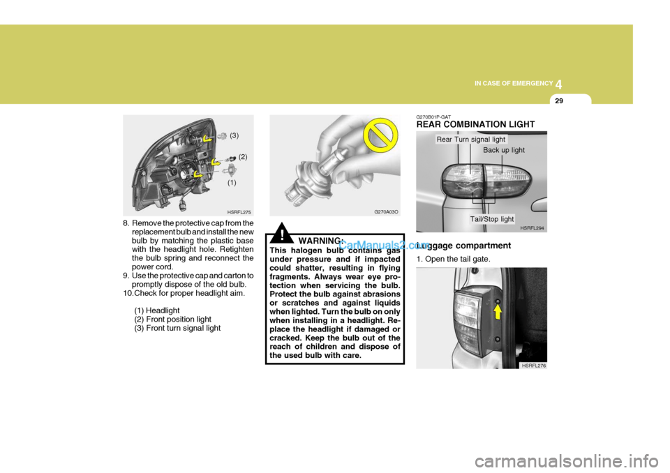
8. Remove the protective cap from the
replacement bulb and install the new bulb by matching the plastic base with the headlight hole. Retighten the bulb spring and reconnect thepower cord.
9. Use the protective cap and carton to
promptly dispose of the old bulb.
10.Check for proper headlight aim.
(1) Headlight(2) Front position light (3) Front turn signal light HSRFL275
(1)
(2)
(3)
!
G270A03O
WARNING:
This halogen bulb contains gas under pressure and if impacted could shatter, resulting in flying fragments. Always wear eye pro-tection when servicing the bulb. Protect the bulb against abrasions or scratches and against liquidswhen lighted. Turn the bulb on only when installing in a headlight. Re- place the headlight if damaged orcracked. Keep the bulb out of the reach of children and dispose of the used bulb with care.
HSRFL276
G270B01P-GAT REAR COMBINATION LIGHT Luggage compartment 1. Open the tail gate.
HSRFL294
Rear Turn signal light
Back up light
Tail/Stop light
Page 207 of 273
4
CORROSION PREVENTION AND APPEARANCE CARE
35
4
IN CASE OF EMERGENCY
35
7
96
Front Rear (Glow type/Fluorescent type)
High/LowTurn signal lightPosition light Map light Room light Wattage
21
16/5(LED) 5
21/5(O/S LAMP) 5(I/S LAMP) 21 165
Part Name
Rear fog lightHigh mounted stop lightLicense plate light Rear combination lightStep light
NO.
6 78 9
10
Part Name
Headlight Front fog lightInteriorSide repeater Door edge warning light
BULB WATTAGE
G280A01P-GAT MINIBUS/VAN
G280A01P
NO.1 234 5 Wattage
60/55 215
55 8
1010 55
1 23
45
Stop/tail light Turn signal light Back up light
810
Page 208 of 273
44IN CASE OF EMERGENCY
36
NO.
4 56 Part Name
Side repeaterRear combination lightLicense plate light Wattage
10 21 21215
G280B01P-GAT TRUCK
G280B01PNO.1 2 3 Part Name
Front fog light Headlight Interior Wattage
55
55/55
215
55
8
1 23
4 65
High/Low Turn signal lightPosition light Map light Room lightStop/tail light Turn signal light Back up light
Page 270 of 273

10
INDEX
3
D
DAY/NIGHT INSIDE REARVIEW MI RROR .............2-34
DEFROSTING/DEFOGGING ...................................2-43
DIGITAL CLOCK ...................................................... 2-37
DOOR LOCKS .......................................................... 1-12
DRINK HOLDER ....................................................... 2-35
DRIVING FOR ECONOMY ......................................3-25
DRIVING WITH ELECTRONIC DUAL-RANGE AUTOMATIC TRANSM ISSION ............................. 3-13
EEMISSION CONTROL SYSTEM ............................... 7-2
ENGINE ...................................................................... 9-3
ENGINE COMPARTMENT ......................... ................ 8-2
ENGINE COOLANT .................................................. 8-10
ENGINE COOLANT TEM PERATURE GAUGE.......2-12
ENGINE NUMBER ..................................................... 1-5
ENGINE OI L ............................................................... 8-7
ENGINE RPM ADJUSTMENT KNOB ......................2-24
EXPLANATION OF SCHEDULED MAINTENANCE ITEMS .............. ...........................6-12
FFOUR-WHEEL DRIVE (4WD) ..................................3-15
FRONT DOOR EDGE WARNING LIGHT ...............2-25
FRONT DOOR WINDOW GLASS ...........................1-25
FRONT FOG LIGHT SWITCH .................................2-25FRONT/REAR WINDOW DEFROSTER
SWITCH .. 2-26
FUEL GAUGE ........................................................... 2-12
FUEL TANK CAPACITY ............................................. 9-2
FUSE PANEL DESCRIPTION ..................................4-37
GGENERAL CHECKS ................................................... 8-6
GOOD BRAKING PRACTICE ..................................3-22
HHAZARD WARNING SYSTEM................................ 2-26
HEADLIGHT AIMING ADJUSTMENT ......................4-26
HEADLIGHT LEVELING DEVICE SYSTEM ............2-23
HEADREST ............................................................... 1-35
HEATING AND COOLING CONTROL ....................2-38
HEATING CONTROLS ............................................. 2-42
HEIGHT ADJUSTABLE FRONT SEAT SHOULDER BELT ...................................................................... 1-38
HIGH-MOUNTED REAR STOP LIGHT ...................2-25
HOLD OPEN LOCK SYSTEM................................. 1-13
HOOD RELEASE ..................................................... 1-23
HORN ........................................................................ 2-37