2004 Hyundai Grandeur oil
[x] Cancel search: oilPage 196 of 235

6- 14 DO-IT-YOURSELF MAINTENANCE
G110B04A-AAT
Recommended Fluid
Your Hyundai automatic transaxle is specially designed to operate withHYUNDAI GENUINE ATF SP III, DIA- MOND ATF SP III, SK ATF SP III or other brands approved by HyundaiMotor Co., Damage caused by a nonspecified fluid is not covered by your new vehicle limited warranty.
G110C02L-GAT
Transaxle Fluid Capacity
The fluid capacity of the automatictransaxle is 7.8 liters (2.5 V6)/8.5 liters (3.0/3.5 V6).
HXG065
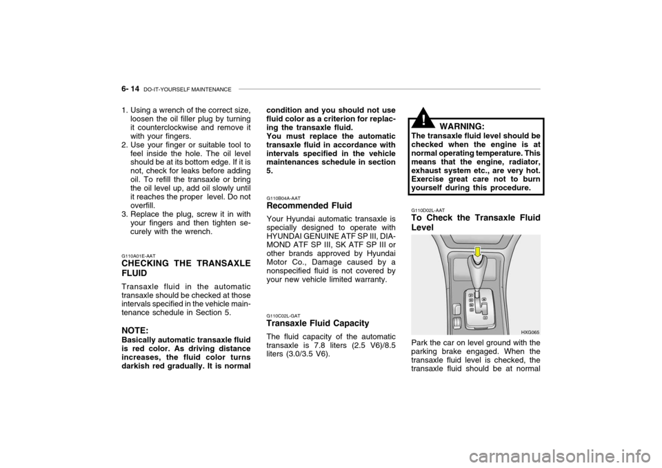
G110D02L-AAT
To Check the Transaxle Fluid Level
Park the car on level ground with the
parking brake engaged. When the transaxle fluid level is checked, the transaxle fluid should be at normal
G110A01E-AAT CHECKING THE TRANSAXLE FLUID Transaxle fluid in the automatic transaxle should be checked at those intervals specified in the vehicle main- tenance schedule in Section 5. NOTE: Basically automatic transaxle fluid is red color. As driving distance increases, the fluid color turns darkish red gradually. It is normal
1. Using a wrench of the correct size,
loosen the oil filler plug by turningit counterclockwise and remove itwith your fingers.
2. Use your finger or suitable tool to
feel inside the hole. The oil level should be at its bottom edge. If it is not, check for leaks before addingoil. To refill the transaxle or bring the oil level up, add oil slowly until it reaches the proper level. Do notoverfill.
3. Replace the plug, screw it in with
your fingers and then tighten se-curely with the wrench. condition and you should not use fluid color as a criterion for replac- ing the transaxle fluid.
You must replace the automatic
transaxle fluid in accordance withintervals specified in the vehicle maintenances schedule in section 5. WARNING:
The transaxle fluid level should bechecked when the engine is at normal operating temperature. This means that the engine, radiator,exhaust system etc., are very hot. Exercise great care not to burn yourself during this procedure.
!
Page 205 of 235

DO-IT-YOURSELF MAINTENANCE 6- 23
G210A01A-AAT
CHECKING THE BATTERY
WARNING:
Batteries can be dangerous! When working with batteries, care-
fully observe the following pre- cautions to avoid serious injuries.
The fluid in the battery contains a
strong solution of sulfuric acid, whichis poisonous and highly corrosive. Be careful not to spill it on yourself or thecar. If you do spill battery fluid on yourself, immediately do the follow- ing:
o If battery fluid is on your skin, flush the affected areas with water for at least 15 minutes and then seek medical assistance.
o If battery fluid is in your eyes, rinse
out your eyes with water and getmedical assistance as soon as possible. While you are being driven to get medical assistance, continueto rinse your eyes by using a sponge or soft cloth saturated with water. o If you swallow battery fluid, drink a
large quantity of water or milk fol-lowed by milk of magnesia, eat araw egg or drink vegetable oil. Get medical assistance as soon as pos- sible.
While batteries are being charged(either by a battery charger or by the vehicle's generator), they produce explosive gases. Always observethese warnings to prevent injuries from occurring:
o Charge batteries only in a well ven- tilated area.
o Do not permit flames, sparks or
smoking in the area.
o Keep children away from the area. G210B01A-AAT Checking the Battery Keep the battery clean. Any evidence of corrosion around the battery posts or terminals should be removed using a solution of household baking sodaand warm water. After the battery terminals are dry, cover them with a light coating of grease.
!
G220A01A-AAT
CHECKING ELECTRIC COOL- ING FANS
WARNING:
The cooling fan is controlled by
engine coolant temperature and may sometimes operate even whenthe engine is not running. Use extreme caution when working near the blades of the cooling fan,so that you are not injured by a rotating fan blade. As the coolant temperature decreases the fan willautomatically shut off. This is a normal condition.
G220B01A-AAT
Checking Engine Cooling Fan
The engine cooling fan should come
on automatically if the engine coolanttemperature is high.
G220C01A-AAT
Checking Condenser Cooling Fan
The condenser cooling fan should
come on automatically whenever the air conditioning is in operation.
!
Page 206 of 235

6- 24 DO-IT-YOURSELF MAINTENANCE
G240A01A-AAT
POWER STEERING HOSES
It is suggested that you check the power steering hose connections forfluid leakage at regular intervals.The power steering hoses should bereplaced if there is severe surface cracking, scuffing or worn spots. De- terioration of the hose could causepremature failure.
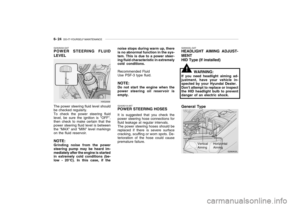
G230A03A-GAT POWER STEERING FLUID LEVEL
HXG2006
The power steering fluid level should be checked regularly. To check the power steering fluid level, be sure the ignition is "OFF", then check to make certain that the power steering fluid level is betweenthe "MAX" and "MIN" level markings on the fluid reservoir. NOTE: Grinding noise from the power steering pump may be heard im-mediately after the engine is started in extremely cold conditions (be- low - 20°C). In this case, if the noise stops during warm up, there is no abnormal function in the sys- tem. This is due to a power steer-ing fluid characteristic in extremely cold conditions.
Recommended Fluid Use PSF-3 type fluid. NOTE: Do not start the engine when the
power steering oil reservoir is empty.
G290A02L-GAT
HEADLIGHT AIMING ADJUST- MENT
HID Type (If installed)
WARNING:
If you need headlight aiming ad- justment, have your vehicle in- spected by your Hyundai Dealer. Don't attempt to replace or inspect the HID headlight bulb to prevent danger of an electric shock.
Vertical Aiming HorizontalAiming
!
G290A02L
General Type
Page 207 of 235

DO-IT-YOURSELF MAINTENANCE 6- 25
Before performing aiming adjustment,
make sure of the following.
1. Keep all tires inflated to the correct
pressure.
2. Place the vehicle on level ground
and press the front bumper & rear bumper down several times. Place the vehicle at a distance of 3 m (118 in.) from the test wall.
3. See that the vehicle is unloaded (except for full levels of coolant,engine oil and fuel, and spare tire,jack, and tools). Have the driver or equivalent weight placed in driver's seat.
4. Clean the head light lenses and
turn on the headlights (low beam).
5. Open the hood.
6. Draw the vertical line (through the center of each headlight) and the horizontal line (through the center of each headlight) on the aimingscreen. And then, draw a parallel line at 30 mm (1.18 in.) under the horizontal line. G290B02L-GAT
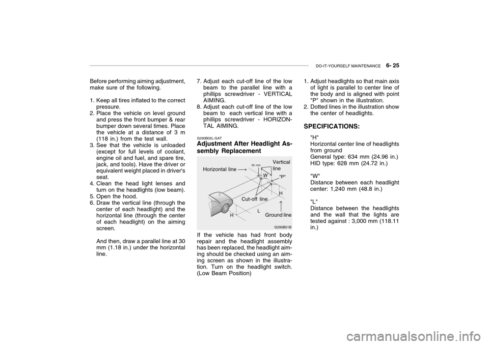
Adjustment After Headlight As- sembly Replacement
If the vehicle has had front body
repair and the headlight assembly has been replaced, the headlight aim- ing should be checked using an aim-ing screen as shown in the illustra- tion. Turn on the headlight switch. (Low Beam Position)
7. Adjust each cut-off line of the low
beam to the parallel line with aphillips screwdriver - VERTICALAIMING.
8. Adjust each cut-off line of the low
beam to each vertical line with a phillips screwdriver - HORIZON- TAL AIMING. 1. Adjust headlights so that main axis
of light is parallel to center line ofthe body and is aligned with point"P" shown in the illustration.
2. Dotted lines in the illustration show
the center of headlights.
SPECIFICATIONS: "H"Horizontal center line of headlightsfrom groundGeneral type: 634 mm (24.96 in.) HID type: 628 mm (24.72 in.) "W" Distance between each headlightcenter: 1,240 mm (48.8 in.) "L" Distance between the headlightsand the wall that the lights aretested against : 3,000 mm (118.11 in.)
G290B01B
L W
Cut-off line Ground line
"P"
Horizontal line
Vertical line30 mm
H H
Page 208 of 235

6- 26 DO-IT-YOURSELF MAINTENANCE
G260A01L-GAT
REPLACEMENT OF LIGHT BULBS
Before attempting to replace a light bulb, be sure the switch is turned tothe "OFF" position.The next paragraph shows how toreach the light bulbs so they may be changed. Be sure to replace the burned-out bulb with one of the samenumber and wattage rating.See page 6-33 for the wattage de-scriptions.
! CAUTION:
o Keep the lights out of contact with petroleum products, such as oil, gasoline, etc.
o Be sure to replace the LED type equipped bulbs with an assem-bly.Replacement instructions:
1. Allow the bulb to cool. Wear eye protection.
2. Open the engine hood.
3. Always grasp the bulb by its plastic base, avoid touching the glass. G270A03L
G270A02L-GAT
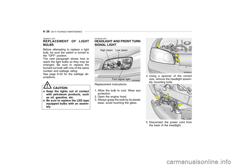
HEADLIGHT AND FRONT TURN SIGNAL LIGHT
High beam Low beam
Turn signal light
G270D01L
4. Using a spanner of the correct size, remove the headlight assem- bly mounting bolts.
G270D02L
5. Disconnect the power cord from the back of the headlight.
Page 216 of 235

6- 34 DO-IT-YOURSELF MAINTENANCE
G200C01L-GAT JUNCTION BOX DESCRIPTION Under Hood Junction Box
G200C01L
NOTE: Not all junction box description in this manual
may be applicable to your vehicle. It is accurate at the time of printing. When you inspect the junction box on your vehicle, refer to the junction box label. DESCRIPTION
FUEL PUMP
HEAD LIGHT(Lo-LH) ABS
INJECTOR
A/C COMPRESSOR A/T
MAIN
IGNITION COIL
OXYGEN SENSOR EGR
HORN
HEAD LIGHT(HI)
HEAD LIGHT(Lo-RH) DRL
FOG LIGHT DIODE 1
SPARE
SPARE
SPARE
SPARE
DIODE 2
BLOWER
POWER FUSE 2 POWER AMPSUNROOF
TAIL LIGHT
POWER FUSE 1 ECU
REAR DEFOGGER CONDENSER
POWER WINDOW IGNITION1/2ABS 1/2
RADIATOR FUSE
RATING
20A15A10A10A10A20A30A 20A 15A 15A15A15A15A15A15A 30A 20A15A10A 30A 30A20A15A20A30A10A30A20A40A
30A/30A30A/30A 30A PROTECTED COMPONENTS
Fuel pump relay
Head light relay (Low-LH)
ABS controls, Cruise control module, ETS control module
Limp home valve, ETS controls, Injector
A/C relay
A/T control relay, TCM, Engine control relayMFI controls
Ignition coil, A/T pulse generator, ECM, Ignition failure
sensor, E/TCM
ETS relay, MFI controls
A/C relay, MFI controls, EGR solenoid
Horn relay
Head light relay (High)
HID head light relay
DRL control module, Siren
Fog light relay - -----
Blower relayFuse 4, 20, 24, 25
Audio amp module
Data link connector, Sunroof relay, Home link connector
Tail light relayFuse 1, 7, 17, 18, 19
ETS control module, ECM, E/TCM, Generator
Rear window defogger relay
A/C fan relay #1
Power window relay, IMS controls
Ignition switchABS controlsRadiator fan relay
Page 227 of 235

9- 2 VEHICLE SPECIFICATIONS
3.0 V6
J010A02L-GAT MEASUREMENT
4,875 (191.8) 1,800 (70.86)
1,420 (55.9)
2,750 (108.2) 1,540 (60.6)
1,530 (60.23)
Overall lengthOverall widthOverall height Wheel base Wheel tread
Front
Rear
Type Wheel free play Rack strokeOil pump type Rack and pinion0 ~ 30 mm (0 ~ 1.18 in.) 146 mm (5.74 in.) Vane type
J060A01L-GAT FUEL SYSTEM
J020A01L-GAT POWER STEERING
Fuel tank capacity 70 Liter J030A03L-GAT TIRE
205/65 R15 94V 205/60 R16 96V
StandardOption
J050A01L-GAT BRAKE
Dual hydraulic with brake booster Ventilated discSolid disc Cable operated on rear wheel
Type Front brake typeRear brake type Parking brake
Item Battery
Alternator 120A (13.5V)
2.5 V6
110A (13.5V)
J040A02L-GAT ELECTRICAL
MF 68AH (MF)
3.5 V6
mm (in.)
Page 228 of 235

VEHICLE SPECIFICATIONS 9- 3
1 - 2 - 3 - 4 - 5 - 6
Auto lash Auto lash
1.0 ~ 1.1 mm 0.7 ~ 0.8 mm 700 ± 100
SH, SG or SG/CD ABOVE multigrade and fuel-efficient oil
3.5 V6
6-Cyl. V-type, DOHC 93 x 85.8
3,497
BTDC 5 2
J070A02L-GAT ENGINE
ITEMS
Bore x Stroke Displacement (cc) Firing order
Valve clearance Intake
(warm engine) Exhaust Spark plug gap Unleaded
Leaded
Idle speed (rpm)Ignition timing Oil grade (API) 3.0 V6
6-Cyl. V-type, DOHC 91.1 x 76
2,972
BTDC 5 22.5 V6
6-Cyl. V-type, DOHC 84 x 75.02,493
BTDC 12 10