Page 198 of 235

6- 16 DO-IT-YOURSELF MAINTENANCE
G120E02A-AAT
Adding Brake Fluid
WARNING:
Handle brake fluid carefully. It can
damage your vision if it gets into your eyes. Use only DOT 3 or DOT 4 specification fluid from a sealedcontainer. Do not allow the fluid can or reservoir to remain open any longer than required. This willprevent entry of dirt and moisture which can damage the brake sys- tem and cause improper opera- tion.G130A01A-AAT
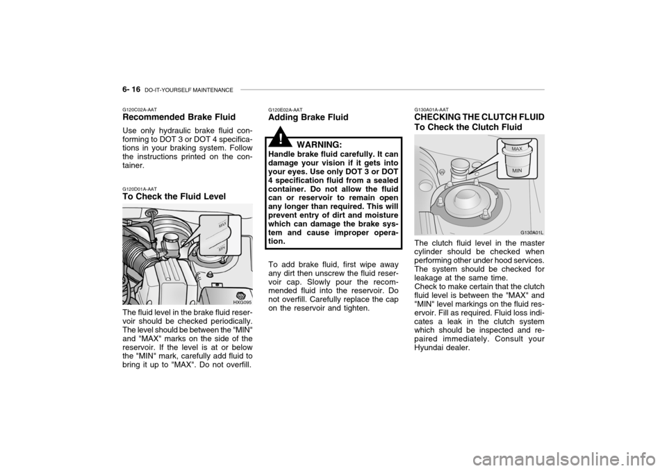
CHECKING THE CLUTCH FLUID To Check the Clutch Fluid
The clutch fluid level in the master
cylinder should be checked when performing other under hood services.The system should be checked for leakage at the same time.
Check to make certain that the clutch
fluid level is between the "MAX" and"MIN" level markings on the fluid res- ervoir. Fill as required. Fluid loss indi-cates a leak in the clutch system which should be inspected and re- paired immediately. Consult yourHyundai dealer. G130A01L
!
To add brake fluid, first wipe away any dirt then unscrew the fluid reser-voir cap. Slowly pour the recom- mended fluid into the reservoir. Do not overfill. Carefully replace the capon the reservoir and tighten.
G120C02A-AAT Recommended Brake Fluid Use only hydraulic brake fluid con- forming to DOT 3 or DOT 4 specifica- tions in your braking system. Follow the instructions printed on the con-tainer. G120D01A-AAT To Check the Fluid Level
HXG095
The fluid level in the brake fluid reser- voir should be checked periodically. The level should be between the "MIN" and "MAX" marks on the side of thereservoir. If the level is at or below the "MIN" mark, carefully add fluid to bring it up to "MAX". Do not overfill.
Page 207 of 235

DO-IT-YOURSELF MAINTENANCE 6- 25
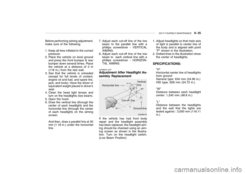
Before performing aiming adjustment,
make sure of the following.
1. Keep all tires inflated to the correct
pressure.
2. Place the vehicle on level ground
and press the front bumper & rear bumper down several times. Place the vehicle at a distance of 3 m (118 in.) from the test wall.
3. See that the vehicle is unloaded (except for full levels of coolant,engine oil and fuel, and spare tire,jack, and tools). Have the driver or equivalent weight placed in driver's seat.
4. Clean the head light lenses and
turn on the headlights (low beam).
5. Open the hood.
6. Draw the vertical line (through the center of each headlight) and the horizontal line (through the center of each headlight) on the aimingscreen. And then, draw a parallel line at 30 mm (1.18 in.) under the horizontal line. G290B02L-GAT
Adjustment After Headlight As- sembly Replacement
If the vehicle has had front body
repair and the headlight assembly has been replaced, the headlight aim- ing should be checked using an aim-ing screen as shown in the illustra- tion. Turn on the headlight switch. (Low Beam Position)
7. Adjust each cut-off line of the low
beam to the parallel line with aphillips screwdriver - VERTICALAIMING.
8. Adjust each cut-off line of the low
beam to each vertical line with a phillips screwdriver - HORIZON- TAL AIMING. 1. Adjust headlights so that main axis
of light is parallel to center line ofthe body and is aligned with point"P" shown in the illustration.
2. Dotted lines in the illustration show
the center of headlights.
SPECIFICATIONS: "H"Horizontal center line of headlightsfrom groundGeneral type: 634 mm (24.96 in.) HID type: 628 mm (24.72 in.) "W" Distance between each headlightcenter: 1,240 mm (48.8 in.) "L" Distance between the headlightsand the wall that the lights aretested against : 3,000 mm (118.11 in.)
G290B01B
L W
Cut-off line Ground line
"P"
Horizontal line
Vertical line30 mm
H H
Page 208 of 235
6- 26 DO-IT-YOURSELF MAINTENANCE
G260A01L-GAT
REPLACEMENT OF LIGHT BULBS
Before attempting to replace a light bulb, be sure the switch is turned tothe "OFF" position.The next paragraph shows how toreach the light bulbs so they may be changed. Be sure to replace the burned-out bulb with one of the samenumber and wattage rating.See page 6-33 for the wattage de-scriptions.
! CAUTION:
o Keep the lights out of contact with petroleum products, such as oil, gasoline, etc.
o Be sure to replace the LED type equipped bulbs with an assem-bly.Replacement instructions:
1. Allow the bulb to cool. Wear eye protection.
2. Open the engine hood.
3. Always grasp the bulb by its plastic base, avoid touching the glass. G270A03L
G270A02L-GAT
HEADLIGHT AND FRONT TURN SIGNAL LIGHT
High beam Low beam
Turn signal light
G270D01L
4. Using a spanner of the correct size, remove the headlight assem- bly mounting bolts.
G270D02L
5. Disconnect the power cord from the back of the headlight.