2004 Hyundai Coupe coolant level
[x] Cancel search: coolant levelPage 153 of 389
DO-IT-YOURSELF MAINTENANCE 6-21
G290A02GK-GAT
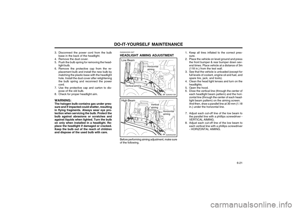
HEADLIGHT AIMING ADJUSTMENT
Horizontal aiming
G290A01GK
Vertical aiming
3. Disconnect the power cord from the bulb
base in the back of the headlight.
4. Remove the dust cover.
5. Push the bulb spring for removing the head- light bulb.
6. Remove the protective cap from the re- placement bulb and install the new bulb by matching the plastic base with the headlighthole. Install the dust cover after retighteningthe bulb spring and reconnect the powercord.
7. Use the protective cap and carton to dis- pose of the old bulb.
8. Check for proper headlight aim.
WARNING: The halogen bulb contains gas under pres-
sure and if impacted could shatter, resulting in flying fragments. Always wear eye pro-tection when servicing the bulb. Protect thebulb against abrasions or scratches andagainst liquids when lighted. Turn the bulbon only when installed in a headlight. Re-place the headlight if damaged or cracked.Keep the bulb out of the reach of childrenand dispose of the used bulb with care.
Before performing aiming adjustment, make sure
of the following.
Low Beam
G290A02GK
Vertical aiming
High Beam
Horizontal aiming1. Keep all tires inflated to the correct pres-
sure.
2. Place the vehicle on level ground and press the front bumper & rear bumper down sev- eral times. Place vehicle at a distance of 3m(118 in.) from the test wall.
3. See that the vehicle is unloaded (except for full levels of coolant, engine oil and fuel, andspare tire, jack, and tools).
4. Clean the head light lenses and turn on the headlights.
5. Open the hood.
6. Draw the vertical line (through the center of each headlight beam pattern) and the hori-zontal line (through the center of each head-light beam pattern) on the aiming screen. And then, draw a parallel line at 30 mm (1.18 in.) under the horizontal line.
7. Adjust each cut-off line of the low beam to the parallel line with a phillips screwdriver -VERTICAL AIMING.
8. Adjust each cut-off line of the low beam to each vertical line with a phillips screwdriver- HORIZONTAL AIMING.
Page 167 of 389

INDEX
10-2
Driving
Economical driving ....................................................................... 2-11
Smooth cornering ......................................................................... 2-11
Winter driving ................................................................................ 2-11
E Emissions Control Systems ................................................................ 7-1
Engine Before starting the engine .............................................................. 2-2
Changing the oil and filter .............................................................. 6-6
Compartment .................................................................................. 6-1
Coolant ........................................................................................... 6-7
Coolant temperature gauge .......................................................... 1-29
If the engine overheats ................................................................... 3-2
Number ........................................................................................... 8-1
Oil .................................................................................................. 6-4 Oil consumption .............................................................................. 6-6
Starting ........................................................................................... 2-3
Engine Exhaust Can Be Dangerous ................................................... 2-1
FFog Li ght ........................................................................................... 1-43
Front Seats Adjustable front seats ..................................................................... 1-8
Adjustable headrests ...................................................................... 1-8Adjusting seat forward and rearward ............................................. 1-8
Adjusting seatback angle ...................... ......................................... 1-8
Lumbar support control ............... ................................................... 1-9
Seat cushion height adjustment ..................................................... 1-9
Seat warm er ................................................................................... 1-9
Fuel
Capacity .......................................................................................... 9-1
Gauge ........................................................................................... 1-28
Recommendations .......................................................................... 1-1 Fuel Filler Lid
Remote release ............................................................................ 1-45
Fuse Panel Description .......................................................... 6-23 ~ 6-24
Fuses ................................................................................................ 6-17
GGeneral Everyday Checks .................................................................. 6-4
Glove box .......................................................................................... 1-41
HHazard Warn ing System ................................................................... 1-36
Headlight Bulb ................................................................................... 6-20
Headlight Leveling Device System ................................................... 1-38
Heating and Cooling Control Rotary type ........................................................................ 1-51 ~ 1-56
Automatic type ................................................................... 1-57 ~ 1-62
High-mounted rear stoplight .............................................................. 1-44
Hood Release ................................................................................... 1-44
Horn ................................................................................................ 1-47
IIgnition Switch ..................................................................................... 2-2
Immobilizer System ............................................................................. 1-2
Infinity Sound System (B260) ........................................................... 1-80
Anti-Theft Device .......................................................................... 1-81
General operation ......................................................................... 1-81
Radio operation ............................................................................ 1-82
CD operation ................................................................................ 1-83
Instrument Cluster and Indicator ....................................................... 1-26
Instrument Panel Light Control (Rheostat) .......................................1-37
Instruments and Controls .................................................................. 1-25
Intermittent Wiper .............................................................................. 1-35
Page 183 of 389

1
CONTROLS AND EQUIPMENT
3RUNNING IN YOUR NEW HYUNDAI
B020A01S-EAT The longevity and performance of the vehicle are greatly affected by the care exercised during the first 1,000 miles of motoring. Because of modern manu-facturing techniques, rigid guidelines regarding maximum road speeds have become unnecessary. However, cer-tain precautions should be observed in order to obtain the best possible per- formance and useful life from the ve-hicle.
1) Do not race the engine without a
load (i.e revving the engine in neu- tral).
2) During the first 500 miles the maxi- mum engine speed should be re-stricted to 3,000 rpm and gradually increased thereafter.
3) Avoid prolonged constant speed operation. The internal componentsof the engine will become morequickly run in if the operation speed is varied during the running in pe- riod.
4) Never allow the engine to labour. Use the gearbox freely and avoidlarge throttle openings when theengine speed is below 1,500 rpm.BEFORE ENTERING THE VEHICLEAFTER ENTERING THE VEHICLE
YB020A1-E
o Ensure that all windows, mirrors
and lamps are clean.
o Check condition of all tyres.
o Ensure that no fluid leaks are evi-
dent.
o Ensure that the area around the vehicle is clear before driving off. YB020B1-E
o Ensure that all occupants fasten
and correctly adjust seat belts.
o Ensure that seat and headrestraint positions are adjusted for optimum safety, control and comfort.
o Adjust interior and exterior rear view mirrors.
o Verify correct operation of lamps, horn and other electrical equipment.
o Ensure that warning lamps illumi-
nate when ignition is turned on.
NOTE: Fluid levels such as engine oil, en- gine coolant, brake and windscreenwasher fluid should be checked daily or at each refuelling, which- ever occurs sooner.
Page 219 of 389
1
CONTROLS AND EQUIPMENT
39
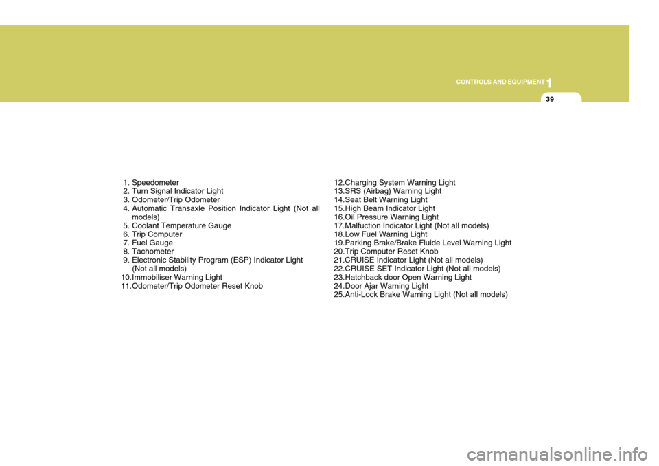
1. Speedometer
2. Turn Signal Indicator Light
3. Odometer/Trip Odometer
4. Automatic Transaxle Position Indicator Light (Not all models)
5. Coolant Temperature Gauge
6. Trip Computer
7. Fuel Gauge
8. Tachometer
9. Electronic Stability Program (ESP) Indicator Light (Not all models)
10.Immobiliser Warning Light
11.Odometer/Trip Odometer Reset Knob 12.Charging System Warning Light
13.SRS (Airbag) Warning Light
14.Seat Belt Warning Light
15.High Beam Indicator Light
16.Oil Pressure Warning Light
17.Malfuction Indicator Light (Not all models)
18.Low Fuel Warning Light
19.Parking Brake/Brake Fluide Level Warning Light
20.Trip Computer Reset Knob21.CRUISE Indicator Light (Not all models)
22.CRUISE SET Indicator Light (Not all models)
23.Hatchback door Open Warning Light
24.Door Ajar Warning Light
25.Anti-Lock Brake Warning Light (Not all models)
Page 224 of 389
1CONTROLS AND EQUIPMENT
44
!
INSTRUMENT CLUSTER
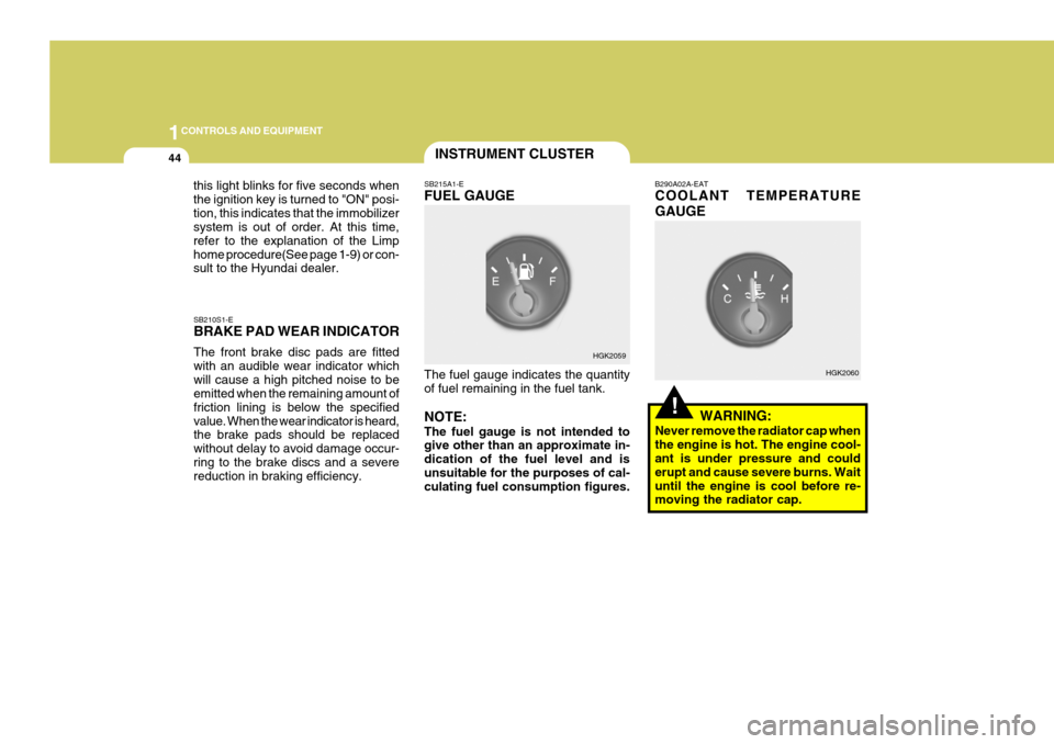
SB210S1-E BRAKE PAD WEAR INDICATOR The front brake disc pads are fitted with an audible wear indicator whichwill cause a high pitched noise to be emitted when the remaining amount of friction lining is below the specifiedvalue. When the wear indicator is heard, the brake pads should be replaced without delay to avoid damage occur-ring to the brake discs and a severe reduction in braking efficiency. SB215A1-E FUEL GAUGE The fuel gauge indicates the quantity of fuel remaining in the fuel tank. NOTE: The fuel gauge is not intended to give other than an approximate in- dication of the fuel level and isunsuitable for the purposes of cal- culating fuel consumption figures. B290A02A-EAT COOLANT TEMPERATURE GAUGE
WARNING:
Never remove the radiator cap when the engine is hot. The engine cool- ant is under pressure and could erupt and cause severe burns. Waituntil the engine is cool before re- moving the radiator cap.
HGK2059
HGK2060
this light blinks for five seconds when the ignition key is turned to "ON" posi-tion, this indicates that the immobilizer system is out of order. At this time, refer to the explanation of the Limphome procedure(See page 1-9) or con- sult to the Hyundai dealer.
Page 225 of 389
1
CONTROLS AND EQUIPMENT
45
!
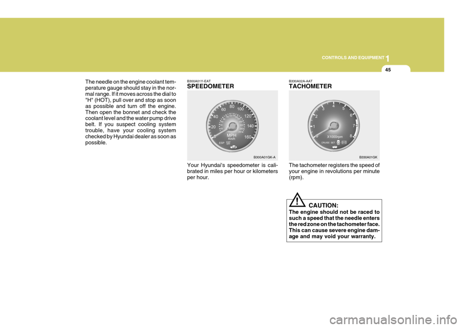
The needle on the engine coolant tem- perature gauge should stay in the nor-mal range. If it moves across the dial to "H" (HOT), pull over and stop as soon as possible and turn off the engine.Then open the bonnet and check the coolant level and the water pump drive belt. If you suspect cooling systemtrouble, have your cooling system checked by Hyundai dealer as soon as possible.
B300A01Y-EAT SPEEDOMETER Your Hyundai's speedometer is cali- brated in miles per hour or kilometers per hour.B330A02A-AAT TACHOMETER The tachometer registers the speed of your engine in revolutions per minute (rpm).
CAUTION:
The engine should not be raced tosuch a speed that the needle entersthe red zone on the tachometer face. This can cause severe engine dam- age and may void your warranty.
B300A01GK-A
B330A01GK
Page 303 of 389
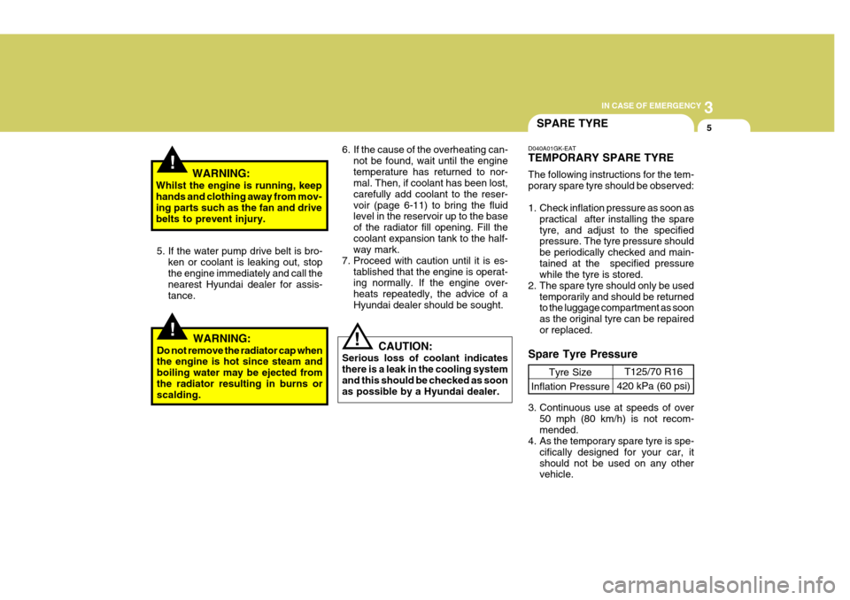
3
IN CASE OF EMERGENCY
5
!
!WARNING:
Whilst the engine is running, keep hands and clothing away from mov- ing parts such as the fan and drive belts to prevent injury.
5. If the water pump drive belt is bro- ken or coolant is leaking out, stop the engine immediately and call the nearest Hyundai dealer for assis-tance.
WARNING:
Do not remove the radiator cap when the engine is hot since steam and boiling water may be ejected fromthe radiator resulting in burns or scalding.
!
6. If the cause of the overheating can- not be found, wait until the engine temperature has returned to nor- mal. Then, if coolant has been lost, carefully add coolant to the reser-voir (page 6-11) to bring the fluid level in the reservoir up to the base of the radiator fill opening. Fill thecoolant expansion tank to the half- way mark.
7. Proceed with caution until it is es- tablished that the engine is operat-ing normally. If the engine over- heats repeatedly, the advice of aHyundai dealer should be sought.
CAUTION:
Serious loss of coolant indicatesthere is a leak in the cooling systemand this should be checked as soon as possible by a Hyundai dealer.D040A01GK-EAT TEMPORARY SPARE TYRE The following instructions for the tem- porary spare tyre should be observed:
1. Check inflation pressure as soon as practical after installing the spare tyre, and adjust to the specified pressure. The tyre pressure should be periodically checked and main-tained at the specified pressure while the tyre is stored.
2. The spare tyre should only be used temporarily and should be returnedto the luggage compartment as soon as the original tyre can be repairedor replaced.
SPARE TYRE
Tyre Size
Inflation Pressure T125/70 R16
420 kPa (60 psi)
Spare Tyre Pressure
3. Continuous use at speeds of over 50 mph (80 km/h) is not recom- mended.
4. As the temporary spare tyre is spe-
cifically designed for your car, itshould not be used on any other vehicle.
Page 324 of 389

5VEHICLE MAINTENANCE REQUIREMENTS
8
6ZF060F1-A
o Vacuum, crankcaseventilation hoses
Inspect the surface of hoses for evi- dence of heat and/or mechanical dam- age. Hard and brittle rubber, cracking, tears, cuts, abrasions, and excessiveswelling indicate deterioration. Particu- lar attention should be paid to examin- ing those hose surfaces nearest tohigh heat sources, such as the ex- haust manifold. Inspect the hose routing to assure that the hoses do not come in contact with any heat source, sharp edges or mov- ing component which might cause heatdamage or mechanical wear. Inspect all hose connections, such as clamps and couplings, to make sure they aresecure, and that no leaks are present. Hoses should be replaced immedi- ately if there is any evidence of dete-rioration or damage. 6ZF060H1-A
o Air cleaner filter
A Genuine Hyundai air cleaner filter is
recommended when the filter is re- placed.
6ZF060J1-A
o Spark plugs
Make sure to install new spark plugs
of the correct heat range.
F060N02E-EAT
o Valve Clearance
Inspect excessive valve noise and/or
engine vibration and adjust if neces- sary. A qualified technician should perform the operation. 6ZF070B1-A
o Cooling system
Check the cooling system part, such
as radiator, coolant reservoir, hosesand connections for leakage and dam- age. Replace any damaged parts.
6ZF070C1-A
o Coolant
The coolant should be changed at
the intervals specified in the mainte-nance schedule.
6ZF070D1-A
o Manual transaxle oil
Inspect the manual transaxle oil ac-
cording to the maintenance schedule. NOTE:
If the oil level is low, check for
possible leaks before adding oil. Do not overfill.