2004 Hyundai Coupe low oil pressure
[x] Cancel search: low oil pressurePage 220 of 389

1CONTROLS AND EQUIPMENT
40
!
!
WARNING AND INDICATOR LIGHTS
SB210K1-ELOW OIL PRESSURE WARN ING LAMP
SB210G1-ETURN SIGNAL INDICA- TOR LAMPS
Operation of a turn signal is indicated by the warning lamp located in theinstrument cluster. If the lamp fails to illuminate or does not flash, a malfunc- tion within the turn signal system isindicated. 260P02Y-EAT ABS Service Reminder Indicator (Not all models)
When the key is turned to the "ON" position, the Anti-Lock Brake System SRI will come on and then go off in afew seconds. If the ABS SRI remains on, comes on while driving, or does not come on when the key is turned to the"ON" position, this indicates that there may be a problem with the ABS. If this occurs, have your vehiclechecked by your Hyundai dealer as soon as possible. The normal braking system will still be operational, butwithout the assistance of the anti-lock brake system. WARNING:
If the both ABS SRI and ParkingBrake/Brake fluid level warning lights remain "ON" or come on whiledriving, there may be a problem with E.B.D (Electronic brake force distribution).If this occurs, avoid sudden stops and have your vehicle checked by your Hyundai dealer as soon aspossible.SB210J1-E HIGH BEAM INDICATOR LAMP
The high beam indicator lamp will illu- minate whenever the headlamps areswitched to high beam of flash posi- tion.
CAUTION:
If the oil pressure warning light illuminates when the engine is run- ning, an insufficient oil pressure level for continued safe operationof the engine exists. Continued operation of the engine in this con- dition may result in serious enginedamage. Under normal circumstances, the light will illuminate when the igni- tion is turned "on" and will be extin- guished when the engine is started.
Page 303 of 389
3
IN CASE OF EMERGENCY
5
!
!WARNING:
Whilst the engine is running, keep hands and clothing away from mov- ing parts such as the fan and drive belts to prevent injury.
5. If the water pump drive belt is bro- ken or coolant is leaking out, stop the engine immediately and call the nearest Hyundai dealer for assis-tance.
WARNING:
Do not remove the radiator cap when the engine is hot since steam and boiling water may be ejected fromthe radiator resulting in burns or scalding.
!
6. If the cause of the overheating can- not be found, wait until the engine temperature has returned to nor- mal. Then, if coolant has been lost, carefully add coolant to the reser-voir (page 6-11) to bring the fluid level in the reservoir up to the base of the radiator fill opening. Fill thecoolant expansion tank to the half- way mark.
7. Proceed with caution until it is es- tablished that the engine is operat-ing normally. If the engine over- heats repeatedly, the advice of aHyundai dealer should be sought.
CAUTION:
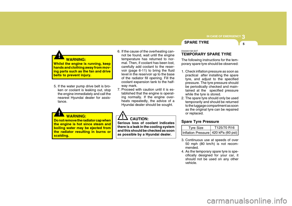
Serious loss of coolant indicatesthere is a leak in the cooling systemand this should be checked as soon as possible by a Hyundai dealer.D040A01GK-EAT TEMPORARY SPARE TYRE The following instructions for the tem- porary spare tyre should be observed:
1. Check inflation pressure as soon as practical after installing the spare tyre, and adjust to the specified pressure. The tyre pressure should be periodically checked and main-tained at the specified pressure while the tyre is stored.
2. The spare tyre should only be used temporarily and should be returnedto the luggage compartment as soon as the original tyre can be repairedor replaced.
SPARE TYRE
Tyre Size
Inflation Pressure T125/70 R16
420 kPa (60 psi)
Spare Tyre Pressure
3. Continuous use at speeds of over 50 mph (80 km/h) is not recom- mended.
4. As the temporary spare tyre is spe-
cifically designed for your car, itshould not be used on any other vehicle.
Page 314 of 389
4
CORROSION PREVENTION AND APPEARANCE CARE
3
4
APPEARANCE CARE
3VALETING
ZE020C1-E INTERIOR During the winter period, it is possible that the carpet within the passengercompartment may become wet. The carpet should not be allowed to remain in this condition for prolonged periodssince the carpet may begin to create musty smells and promote internal corrosion of the floorpan. JE050A2-E Regular cleaning of the exterior paintwork serves two important func- tions. Firstly, the removal of abrasive dirt and contaminants will maintain thelustre of the paintwork and will prevent discolouration and dulling due to pro- longed contact.Secondly, the presence of damage through impact or abrasion will be ap- parent allowing early rectification to bemade thus preventing corrosion from becoming established and spreading beneath the paint film. To avoid "waterspotting" the vehicle should not be washed in direct sunlight particularly in the case of vehicles having dark bodycolours. The heat from the sun rays is absorbed by the paint film increasing the surface temperature. This actioncauses water used for washing to evaporate quickly leaving behind the deposits from the water and the sham-poo used.Use only a shampoo intended for thepurpose and ensure that the body workis thoroughly wetted to soften the dirt film prior to attempting to remove this. After removing the dirt film with a softsponge, the body work should be thor- oughly rinsed and then dried with a good quality chamois leather to pre-vent streaking or spotting of the paint work. Household detergents, solvents andabrasive cleaning materials should not be used in order to avoid damaging the paint film.High pressure car washes may cause water to enter your car. Plastic wheel covers should be cleanedusing a sponge and water. Cast alloy wheels should be cleaned using a mild soap or neutral detergent. Abrasivecompounds must not be used since in the event of these damaging the lac- quer coating, oxidisation of the alu-minium wheel will occur, spoiling the appearance. The use of a toothbrush will facilitatecleaning between the wheel "spokes".
Page 321 of 389
5
VEHICLE MAINTENANCE REQUIREMENTS
5
NO. 1 23 4 5678 9
10 11121314 15 1617181920 21 DESCRIPTION
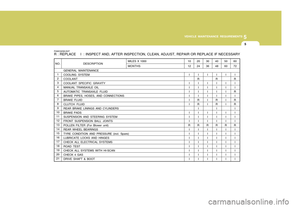
GENERAL MAINTENANCE COOLING SYSTEMCOOLANTCOOLANT SPECIFIC GRAVITYMANUAL TRANSAXLE OILAUTOMATIC TRANSAXLE FLUID BRAKE PIPES, HOSES, AND CONNECTIONS BRAKE FLUIDCLUTCH FLUIDREAR BRAKE LININGS AND CYLINDERSBRAKE PADS SUSPENSION AND STEERING SYSTEM FRONT SUSPENSION BALL JOINTSPOLLEN FILTER (For Blower unit)REAR WHEEL BEARINGSTYRE CONDITION AND PRESSURE (incl. Spare)LUBRICATE LOCKS AND HINGES CHECK ALL ELECTRICAL SYSTEMS ROAD TESTCHECK ALL SYSTEMS WITH HI-SCANCHECK 4 GASDRIVE SHAFT & BOOT
F030C02GK-EAT R : REPLACE I : INSPECT AND, AFTER INSPECTION, CLEAN, ADJUST, REPAIR OR REPLACE IF NECESSARY
60 72
I
R I I
R
I
RR
III I
R
I III I III
50 60
I I III I I I I I
R I III I III
40 48
I
R
I III
RR
III I
R I III I III
30 36
I I III I I I I I
R I III I III
20 24
I
R I III
RR
III I
R I III I III
10 12
I I III I I I I I
R I III I III
MILES X 1000 MONTHS
Page 331 of 389
6
OWNER MAINTENANCE
5ENGINE OIL
SG030A1-E The correct engine oil level is of para-
mount importance. An excessively high or low oil level may result inirreparable damage being sustained by the engine. The engine oil level must be checked on a daily basis orwhenever the vehicle is refuelled, whichever occurs sooner.
In addition, it is imperative that only
an approved grade and specificationof oil is used to avoid the possibility of serious engine damage and prema-ture wear. The use of "budget price" oil is a false economy that must be avoided if the maximum reliability anduseful life is to be obtained from the vehicle.
SG020B1-E The following items should be checked on a daily basis or whenever the vehicle is refuelled, whichever occurssooner.
o Engine oil level.
o Engine coolant level.
o Power steering fluid level.
o Brake fluid level.
o Windscreen washer fluid level.
o Battery condition.
o Tyre condition and pressures.
o Operation and cleanliness of all lighting equip-ment.
o Windscreen wiper and washer op-
eration.
o Horn operation.
o Warning lamp operation.
o Adjustment and cleanliness of mir- rors.
o Seat and seat belt adjustment and operation.
o Fluid leakage.
The vehicle must not be driven if the daily operating checks indicate that any item of equipment related to the safety or roadworthiness of the ve-hicle is not functioning correctly. DAILY OPERATING CHECKS
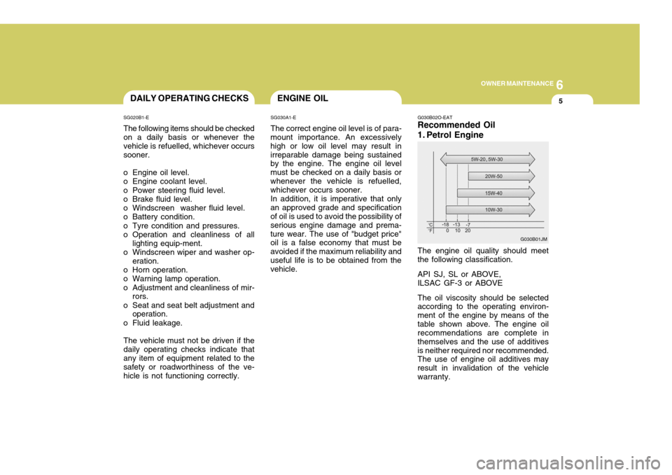
G030B02O-EAT Recommended Oil
1. Petrol Engine The engine oil quality should meet the following classification. API SJ, SL or ABOVE, ILSAC GF-3 or ABOVE The oil viscosity should be selected according to the operating environ- ment of the engine by means of thetable shown above. The engine oil recommendations are complete in themselves and the use of additivesis neither required nor recommended. The use of engine oil additives may result in invalidation of the vehiclewarranty.
G030B01JM
Page 333 of 389
6
OWNER MAINTENANCE
7
HGK5005
SG030D2-E
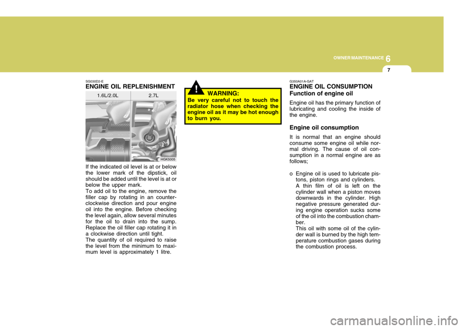
ENGINE OIL REPLENISHMENT
If the indicated oil level is at or below the lower mark of the dipstick, oilshould be added until the level is at or below the upper mark. To add oil to the engine, remove the filler cap by rotating in an counter- clockwise direction and pour engine oil into the engine. Before checkingthe level again, allow several minutes for the oil to drain into the sump. Replace the oil filler cap rotating it ina clockwise direction until tight.The quantity of oil required to raisethe level from the minimum to maxi- mum level is approximately 1 litre. 1.6L/2.0L
G350A01A-GAT ENGINE OIL CONSUMPTION Function of engine oil Engine oil has the primary function of lubricating and cooling the inside of the engine. Engine oil consumption It is normal that an engine should consume some engine oil while nor- mal driving. The cause of oil con- sumption in a normal engine are asfollows;
o Engine oil is used to lubricate pis-
tons, piston rings and cylinders. A thin film of oil is left on the cylinder wall when a piston moves downwards in the cylinder. High negative pressure generated dur-ing engine operation sucks some of the oil into the combustion cham- ber.This oil with some oil of the cylin-der wall is burned by the high tem-perature combustion gases during the combustion process.
2.7L
!WARNING:
Be very careful not to touch the
radiator hose when checking the engine oil as it may be hot enough to burn you.
Page 358 of 389
6OWNER MAINTENANCE
32
G290B01GK-EAT
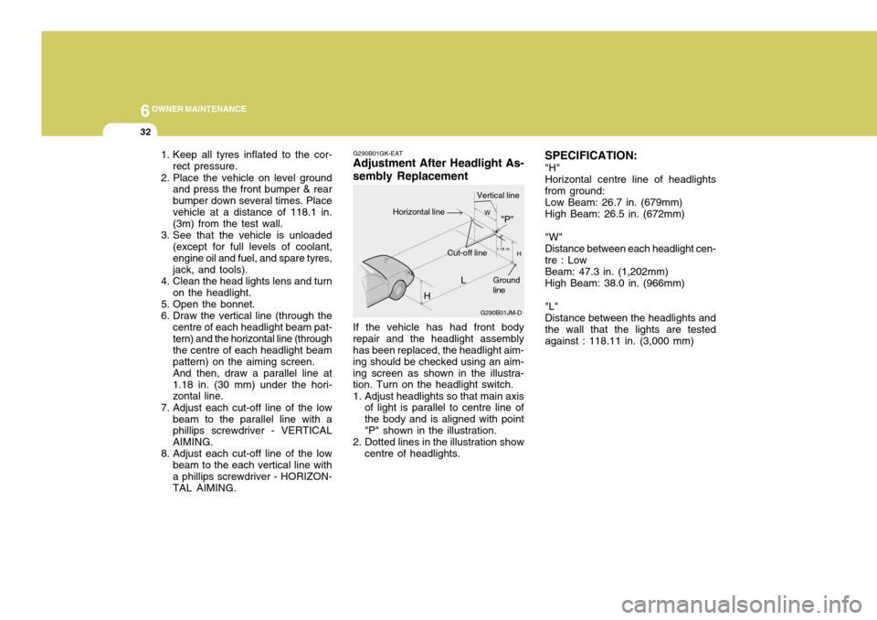
Adjustment After Headlight As- sembly Replacement
If the vehicle has had front body
repair and the headlight assembly has been replaced, the headlight aim- ing should be checked using an aim-ing screen as shown in the illustra- tion. Turn on the headlight switch.
1. Adjust headlights so that main axis of light is parallel to centre line of the body and is aligned with point"P" shown in the illustration.
2. Dotted lines in the illustration show centre of headlights. SPECIFICATION:
"H" Horizontal centre line of headlights from ground: Low Beam: 26.7 in. (679mm) High Beam: 26.5 in. (672mm) "W" Distance between each headlight cen- tre : Low Beam: 47.3 in. (1,202mm) High Beam: 38.0 in. (966mm) "L" Distance between the headlights and the wall that the lights are tested against : 118.11 in. (3,000 mm)
1. Keep all tyres inflated to the cor-
rect pressure.
2. Place the vehicle on level ground and press the front bumper & rearbumper down several times. Placevehicle at a distance of 118.1 in. (3m) from the test wall.
3. See that the vehicle is unloaded (except for full levels of coolant, engine oil and fuel, and spare tyres,jack, and tools).
4. Clean the head lights lens and turn on the headlight.
5. Open the bonnet.
6. Draw the vertical line (through the centre of each headlight beam pat- tern) and the horizontal line (through the centre of each headlight beampattern) on the aiming screen.And then, draw a parallel line at1.18 in. (30 mm) under the hori- zontal line.
7. Adjust each cut-off line of the low beam to the parallel line with aphillips screwdriver - VERTICAL AIMING.
8. Adjust each cut-off line of the low beam to the each vertical line witha phillips screwdriver - HORIZON- TAL AIMING. L
G290B01JM-D
W
H
H Cut-off line"P"
Vertical lineHorizontal line
Ground line
1.18 in.