2004 Hyundai Coupe fuel pressure
[x] Cancel search: fuel pressurePage 219 of 389
1
CONTROLS AND EQUIPMENT
39
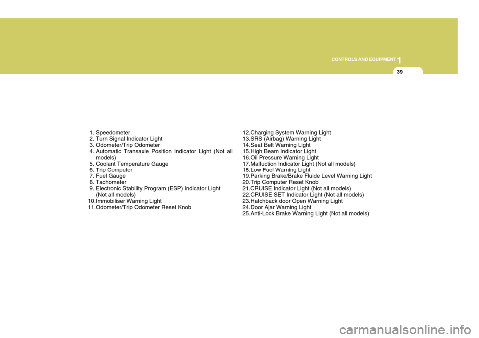
1. Speedometer
2. Turn Signal Indicator Light
3. Odometer/Trip Odometer
4. Automatic Transaxle Position Indicator Light (Not all models)
5. Coolant Temperature Gauge
6. Trip Computer
7. Fuel Gauge
8. Tachometer
9. Electronic Stability Program (ESP) Indicator Light (Not all models)
10.Immobiliser Warning Light
11.Odometer/Trip Odometer Reset Knob 12.Charging System Warning Light
13.SRS (Airbag) Warning Light
14.Seat Belt Warning Light
15.High Beam Indicator Light
16.Oil Pressure Warning Light
17.Malfuction Indicator Light (Not all models)
18.Low Fuel Warning Light
19.Parking Brake/Brake Fluide Level Warning Light
20.Trip Computer Reset Knob21.CRUISE Indicator Light (Not all models)
22.CRUISE SET Indicator Light (Not all models)
23.Hatchback door Open Warning Light
24.Door Ajar Warning Light
25.Anti-Lock Brake Warning Light (Not all models)
Page 224 of 389
1CONTROLS AND EQUIPMENT
44
!
INSTRUMENT CLUSTER
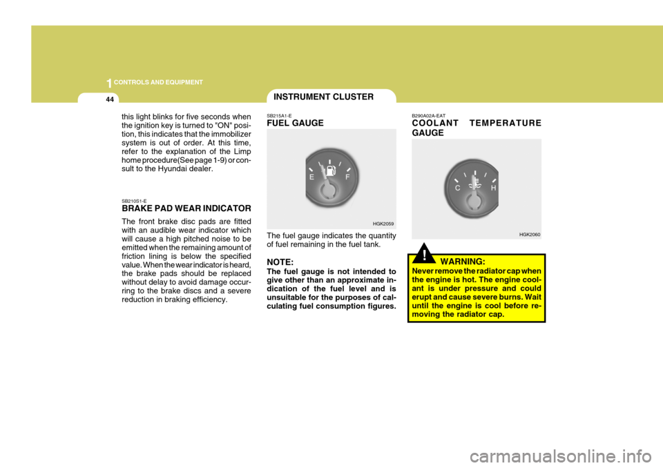
SB210S1-E BRAKE PAD WEAR INDICATOR The front brake disc pads are fitted with an audible wear indicator whichwill cause a high pitched noise to be emitted when the remaining amount of friction lining is below the specifiedvalue. When the wear indicator is heard, the brake pads should be replaced without delay to avoid damage occur-ring to the brake discs and a severe reduction in braking efficiency. SB215A1-E FUEL GAUGE The fuel gauge indicates the quantity of fuel remaining in the fuel tank. NOTE: The fuel gauge is not intended to give other than an approximate in- dication of the fuel level and isunsuitable for the purposes of cal- culating fuel consumption figures. B290A02A-EAT COOLANT TEMPERATURE GAUGE
WARNING:
Never remove the radiator cap when the engine is hot. The engine cool- ant is under pressure and could erupt and cause severe burns. Waituntil the engine is cool before re- moving the radiator cap.
HGK2059
HGK2060
this light blinks for five seconds when the ignition key is turned to "ON" posi-tion, this indicates that the immobilizer system is out of order. At this time, refer to the explanation of the Limphome procedure(See page 1-9) or con- sult to the Hyundai dealer.
Page 281 of 389
2
DRIVING YOUR HYUNDAI
5
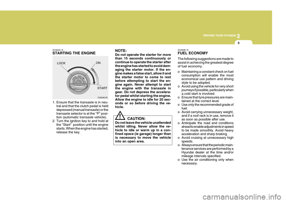
SC060A1-E STARTING THE ENGINE
LOCK SC060B1-EFUEL ECONOMY The following suggestions are made to assist in achieving the greatest degreeof fuel economy.
o Maintaining a constant check on fuel
consumption will enable the most economical use pattern and drivingstyle to be adopted.
o Avoid using the vehicle for very short journeys if possible, particularly whena cold start is involved.
o Ensure that tyre pressures are main- tained at the correct level.
o Use only the recommended grade of fuel.
o Avoid carrying unnecessary weight, and if a roof rack is in use, remove itas soon as possible after use.
o Anticipate the road and conditions ahead to enable adjustments in speedto be made smoothly. Avoid heavyacceleration and sharp braking.
o Avoid cruising at unnecessary high speeds.
o Always ensure that the periodic main- tenance services are performed by aHyundai dealer at the time and/ormileage intervals specified.
o Use the air conditioning only when necessary.
C050A01E
ON
START NOTE: Do not operate the starter for more than 15 seconds continuously or continue to operate the starter afterthe engine has started to avoid dam- aging the starter motor. If the en- gine makes a false start, allow it andthe starter motor to come to rest before attempting to start the en- gine again. Never attempt to startthe engine with the transaxle in gear. Do not depress the accelera- tor pedal whilst starting the engine.Allow the engine to idle for 20 sec- onds or so before driving the ve- hicle.
1. Ensure that the transaxle is in neu-
tral and that the clutch pedal is helddepressed (manual transaxle) or thetransaxle selector is at the "P" posi- tion (automatic transaxle vehicle).
2. Turn the ignition key to and hold at the "Start" position until the enginestarts. When the engine has started, release the key. CAUTION:
Do not leave the vehicle unattendedwhilst idling. Never allow the ve-hicle to idle or warm up in a con- fined space (ie garage) longer than is necessary to move the vehicleinto an open area.
!
Page 297 of 389
2
DRIVING YOUR HYUNDAI
21
!WARNING:
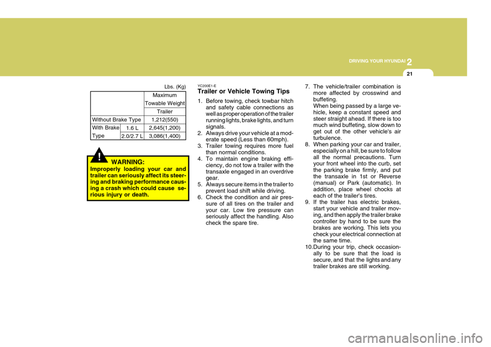
Improperly loading your car and trailer can seriously affect its steer- ing and braking performance caus- ing a crash which could cause se-rious injury or death. Without Brake Type
Maximum
Towable Weight
Trailer
1,212(550)
2,645(1,200) 3,086(1,400)
With Brake Type1.6 L
2.0/2.7 L Lbs. (Kg)
7. The vehicle/trailer combination is
more affected by crosswind and buffeting. When being passed by a large ve- hicle, keep a constant speed andsteer straight ahead. If there is too much wind buffeting, slow down to get out of the other vehicle's airturbulence.
8. When parking your car and trailer,
especially on a hill, be sure to followall the normal precautions. Turn your front wheel into the curb, set the parking brake firmly, and putthe transaxle in 1st or Reverse (manual) or Park (automatic). In addition, place wheel chocks ateach of the trailer's tires.
9. If the trailer has electric brakes,
start your vehicle and trailer mov-ing, and then apply the trailer brake controller by hand to be sure the brakes are working. This lets youcheck your electrical connection at the same time.
10.During your trip, check occasion- ally to be sure that the load issecure, and that the lights and any trailer brakes are still working.
YC200E1-E Trailer or Vehicle Towing Tips
1. Before towing, check towbar hitch
and safety cable connections as well as proper operation of the trailer running lights, brake lights, and turn signals.
2. Always drive your vehicle at a mod- erate speed (Less than 60mph).
3. Trailer towing requires more fuel than normal conditions.
4. To maintain engine braking effi-
ciency, do not tow a trailer with thetransaxle engaged in an overdrive gear.
5. Always secure items in the trailer to prevent load shift while driving.
6. Check the condition and air pres-
sure of all tires on the trailer and your car. Low tire pressure can seriously affect the handling. Also check the spare tire.
Page 331 of 389
6
OWNER MAINTENANCE
5ENGINE OIL
SG030A1-E The correct engine oil level is of para-
mount importance. An excessively high or low oil level may result inirreparable damage being sustained by the engine. The engine oil level must be checked on a daily basis orwhenever the vehicle is refuelled, whichever occurs sooner.
In addition, it is imperative that only
an approved grade and specificationof oil is used to avoid the possibility of serious engine damage and prema-ture wear. The use of "budget price" oil is a false economy that must be avoided if the maximum reliability anduseful life is to be obtained from the vehicle.
SG020B1-E The following items should be checked on a daily basis or whenever the vehicle is refuelled, whichever occurssooner.
o Engine oil level.
o Engine coolant level.
o Power steering fluid level.
o Brake fluid level.
o Windscreen washer fluid level.
o Battery condition.
o Tyre condition and pressures.
o Operation and cleanliness of all lighting equip-ment.
o Windscreen wiper and washer op-
eration.
o Horn operation.
o Warning lamp operation.
o Adjustment and cleanliness of mir- rors.
o Seat and seat belt adjustment and operation.
o Fluid leakage.
The vehicle must not be driven if the daily operating checks indicate that any item of equipment related to the safety or roadworthiness of the ve-hicle is not functioning correctly. DAILY OPERATING CHECKS
G030B02O-EAT Recommended Oil
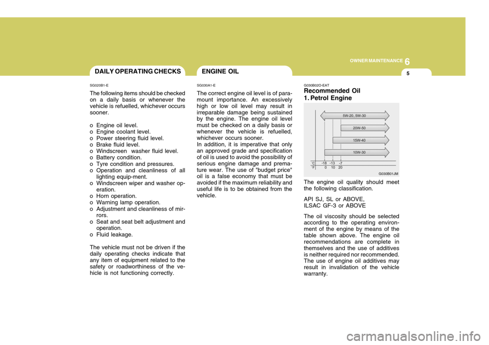
1. Petrol Engine The engine oil quality should meet the following classification. API SJ, SL or ABOVE, ILSAC GF-3 or ABOVE The oil viscosity should be selected according to the operating environ- ment of the engine by means of thetable shown above. The engine oil recommendations are complete in themselves and the use of additivesis neither required nor recommended. The use of engine oil additives may result in invalidation of the vehiclewarranty.
G030B01JM
Page 358 of 389
6OWNER MAINTENANCE
32
G290B01GK-EAT
Adjustment After Headlight As- sembly Replacement
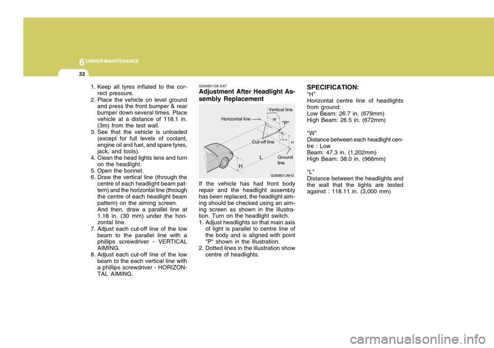
If the vehicle has had front body
repair and the headlight assembly has been replaced, the headlight aim- ing should be checked using an aim-ing screen as shown in the illustra- tion. Turn on the headlight switch.
1. Adjust headlights so that main axis of light is parallel to centre line of the body and is aligned with point"P" shown in the illustration.
2. Dotted lines in the illustration show centre of headlights. SPECIFICATION:
"H" Horizontal centre line of headlights from ground: Low Beam: 26.7 in. (679mm) High Beam: 26.5 in. (672mm) "W" Distance between each headlight cen- tre : Low Beam: 47.3 in. (1,202mm) High Beam: 38.0 in. (966mm) "L" Distance between the headlights and the wall that the lights are tested against : 118.11 in. (3,000 mm)
1. Keep all tyres inflated to the cor-
rect pressure.
2. Place the vehicle on level ground and press the front bumper & rearbumper down several times. Placevehicle at a distance of 118.1 in. (3m) from the test wall.
3. See that the vehicle is unloaded (except for full levels of coolant, engine oil and fuel, and spare tyres,jack, and tools).
4. Clean the head lights lens and turn on the headlight.
5. Open the bonnet.
6. Draw the vertical line (through the centre of each headlight beam pat- tern) and the horizontal line (through the centre of each headlight beampattern) on the aiming screen.And then, draw a parallel line at1.18 in. (30 mm) under the hori- zontal line.
7. Adjust each cut-off line of the low beam to the parallel line with aphillips screwdriver - VERTICAL AIMING.
8. Adjust each cut-off line of the low beam to the each vertical line witha phillips screwdriver - HORIZON- TAL AIMING. L
G290B01JM-D
W
H
H Cut-off line"P"
Vertical lineHorizontal line
Ground line
1.18 in.