Page 199 of 304

•slowly move to a safe place on the side of the road.
The use of tire sealants may damage your tires.
Spare tire information
Your vehicle may be equipped with a spare tire that can be used as
either a spare or a regular tire. The spare tire is not equipped with wheel
trim. The wheel trim from the original wheel/tire may be used on the
spare.
Your vehicle may be equipped with a temporary or conventional spare
tire. If the spare tire is different in size (diameter and/or width), tread
type (All-Season or All-Terrain) or is from a different manufacturer other
than the road tires on your vehicle, your spare tire is considered
“temporary”. Consult information on the spare tire label for limitations
when using.
Location of the spare tire and tools
The spare tire and tools for your vehicle are stowed in the following
locations:
Tool Location
Spare tire (pick-up trucks only) Under the vehicle, just forward of
the rear bumper
Jack Regular cab, Super Cab without
rear bench seat and Crew Cab:
Fastened to floor pan behind
rearmost seat on passenger side
SuperCab with rear bench seat:
Under rear bench on passenger
side
Jack handle and lug wrench Regular cab: Fastened to floor
behind front seat
Super Cab: Fastened to floor
under rear seat
Crew Cab: Fastened to floor
behind rear seat
Key, spare tire lock In the glove box
2004 F250/350/450/550(f23)
Owners Guide (post-2002-fmt)
USA English(fus)
Roadside Emergencies
199
Page 200 of 304
Removing the spare tire (with spare tire carrier only)
1. The following tools are required to remove the spare tire:
•one handle extension and one
typical extension. To assemble,
align button with hole and slide
parts together. To disconnect,
depress button and pull apart.
•one wheel nut wrench. Slide over
square end of jack handle.
•Vehicles equipped with dual
rear wheels,insert the lug
wrench extension into the lug
wrench to reach the lug nuts.
2. Attach the spare tire lock key (A)
to the jack handle (B).
2004 F250/350/450/550(f23)
Owners Guide (post-2002-fmt)
USA English(fus)
Roadside Emergencies
200
Page 201 of 304

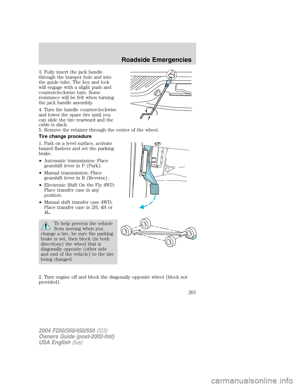
3. Fully insert the jack handle
through the bumper hole and into
the guide tube. The key and lock
will engage with a slight push and
counterclockwise turn. Some
resistance will be felt when turning
the jack handle assembly.
4. Turn the handle counterclockwise
and lower the spare tire until you
can slide the tire rearward and the
cable is slack.
5. Remove the retainer through the center of the wheel.
Tire change procedure
1. Park on a level surface, activate
hazard flashers and set the parking
brake.
•Automatic transmission: Place
gearshift lever in P (Park).
•Manual transmission: Place
gearshift lever in R (Reverse).
•Electronic Shift On the Fly 4WD:
Place transfer case in any
position.
•Manual shift transfer case 4WD:
Place transfer case in 2H, 4H or
4L.
To help prevent the vehicle
from moving when you
change a tire, be sure the parking
brake is set, then block (in both
directions) the wheel that is
diagonally opposite (other side
and end of the vehicle) to the tire
being changed.
2. Turn engine off and block the diagonally opposite wheel (block not
provided).
2004 F250/350/450/550(f23)
Owners Guide (post-2002-fmt)
USA English(fus)
Roadside Emergencies
201
Page 202 of 304

3. Remove the jack, jack handle, lug wrench and spare tire from the
stowage locations.
4. Use the tip of the lug wrench to remove any wheel trim.
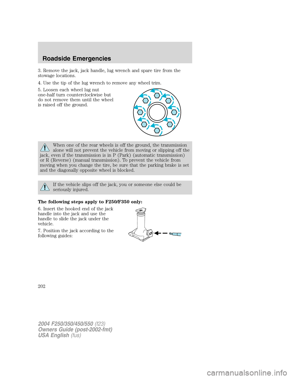
5. Loosen each wheel lug nut
one-half turn counterclockwise but
do not remove them until the wheel
is raised off the ground.
When one of the rear wheels is off the ground, the transmission
alone will not prevent the vehicle from moving or slipping off the
jack, even if the transmission is in P (Park) (automatic transmission)
or R (Reverse) (manual transmission). To prevent the vehicle from
moving when you change the tire, be sure that the parking brake is set
and the diagonally opposite wheel is blocked.
If the vehicle slips off the jack, you or someone else could be
seriously injured.
The following steps apply to F250/F350 only:
6. Insert the hooked end of the jack
handle into the jack and use the
handle to slide the jack under the
vehicle.
7. Position the jack according to the
following guides:
2004 F250/350/450/550(f23)
Owners Guide (post-2002-fmt)
USA English(fus)
Roadside Emergencies
202
Page 204 of 304

•Rear
Never use the front or rear
differential as a jacking point.
To lessen the risk of
personal injury, do not put
any part of your body under the
vehicle while changing a tire. Do
not start the engine when your
vehicle is on the jack. The jack is
only meant for changing the tire.
8. Turn the jack handle clockwise
until the wheel is completely off the
ground and high enough to install
the spare tire.
9. Remove the lug nuts with the lug
wrench.
10. Replace the flat tire with the
spare tire, making sure the valve
stem is facing outward for all front wheels and single rear wheel vehicles.
If replacing an inboard rear tire on dual rear wheel vehicles, the valve
stem must be facing outward. If replacing the outboard wheel, the valve
stem must be facing inward. Reinstall the lug nuts until the wheel is
snug against the hub. Do not fully tighten the lug nuts until the wheel
has been lowered.
11. Lower the wheel by turning the jack handle counterclockwise.
Go to step 19.
2004 F250/350/450/550(f23)
Owners Guide (post-2002-fmt)
USA English(fus)
Roadside Emergencies
204
Page 206 of 304
•Front passenger side (4x4)
•Rear
14. Insert the jack handle into the
pump linkage.
15. Use an up-and-down motion
with the jack handle to raise the
wheel completely off the ground.
Hydraulic jacks are equipped
with a pressure release valve
that prevents lifting loads which
exceed the jack’s rated capacity.
16. Remove the lug nuts with the lug wrench.
17. Replace the flat tire with the spare tire, making sure the valve stem
is facing outward on all front an inboard rear wheels. If replacing the
outboard wheel, the valve stem must be facing inward. Reinstall the lug
nuts until the wheel is snug against the hub. Do not fully tighten the lug
nuts until the wheel has been lowered.
18. Lower the wheel by slowly turning the release valve
counterclockwise. Opening the release valve slowly will provide a more
controlled rate of descent.
2004 F250/350/450/550(f23)
Owners Guide (post-2002-fmt)
USA English(fus)
Roadside Emergencies
206
Page 207 of 304

The following steps apply to all vehicles:
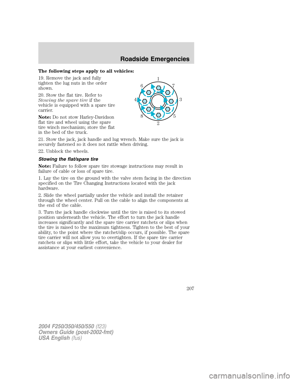
19. Remove the jack and fully
tighten the lug nuts in the order
shown.
20. Stow the flat tire. Refer to
Stowing the spare tireif the
vehicle is equipped with a spare tire
carrier.
Note:Do not stow Harley-Davidson
flat tire and wheel using the spare
tire winch mechanism; store the flat
in the bed of the truck.
21. Stow the jack, jack handle and lug wrench. Make sure the jack is
securely fastened so it does not rattle when driving.
22. Unblock the wheels.
Stowing the flat/spare tire
Note:Failure to follow spare tire stowage instructions may result in
failure of cable or loss of spare tire.
1. Lay the tire on the ground with the valve stem facing in the direction
specified on the Tire Changing Instructions located with the jack
hardware.
2. Slide the wheel partially under the vehicle and install the retainer
through the wheel center. Pull on the cable to align the components at
the end of the cable.
3. Turn the jack handle clockwise until the tire is raised to its stowed
position underneath the vehicle. The effort to turn the jack handle
increases significantly and the spare tire carrier ratchets or slips when
the tire is raised to the maximum tightness. Tighten to the best of your
ability, to the point where the ratchet/slip occurs, if possible. The spare
tire carrier will not allow you to overtighten. If the spare tire carrier
ratchets or slips with little effort, take the vehicle to your dealer for
assistance at your earliest convenience.
1
3 4
27 6
5 8
2004 F250/350/450/550(f23)
Owners Guide (post-2002-fmt)
USA English(fus)
Roadside Emergencies
207
Page 208 of 304

4. Check that the tire lies flat against the frame and is properly
tightened. Try to push or pull, then turn the tire to be sure it will not
move. Loosen and retighten, if necessary. Failure to properly stow the
spare tire may result in failure of the winch cable and loss of the tire.
5. Repeat this tightness check procedure when servicing the spare tire
pressure (every six months, per scheduled maintenance guide), or at any
time that the spare tire is disturbed through service of other
components.
6. If removed, install the spare tire lock (if equipped) into the bumper
drive tube with the spare tire lock key (if equipped) and jack handle.
Wheel lug nut torque specifications
On vehicles equipped with single rear wheels, retighten the lug nuts to
the specified torque at 800 km (500 miles) after any wheel disturbance
(tire rotation, changing a flat tire, wheel removal, etc.).
On vehicles equipped with dual rear wheels, retighten the wheel lug nuts
to the specified torque at 160 km (100 miles), and again at 800 km (500
miles) of new vehicle operation and after any wheel disturbance (tire
rotation, changing a flat tire, wheel removal, etc.).
Bolt size Wheel lug nut torque*
Nm Lb-ft
M14 x 1.5 200-225 150-165
* Torque specifications are for nut and bolt threads free of dirt and
rust. Use only Ford recommended replacement fasteners.
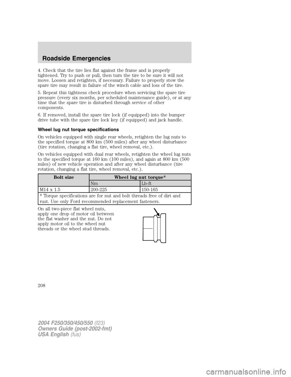
On all two-piece flat wheel nuts,
apply one drop of motor oil between
the flat washer and the nut. Do not
apply motor oil to the wheel nut
threads or the wheel stud threads.
2004 F250/350/450/550(f23)
Owners Guide (post-2002-fmt)
USA English(fus)
Roadside Emergencies
208