Page 1 of 120
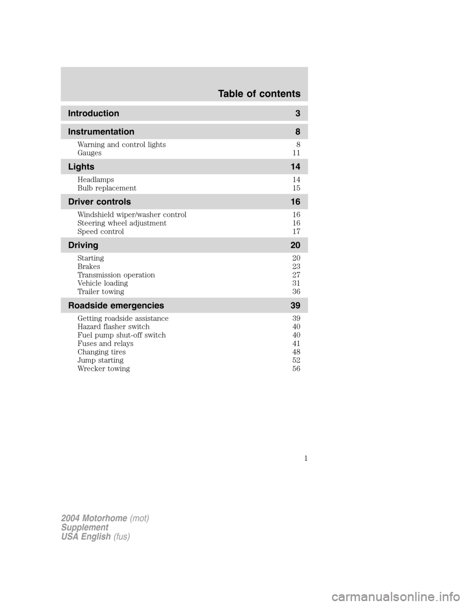
Introduction 3
Instrumentation 8
Warning and control lights 8
Gauges 11
Lights 14
Headlamps 14
Bulb replacement 15
Driver controls 16
Windshield wiper/washer control 16
Steering wheel adjustment 16
Speed control 17
Driving 20
Starting 20
Brakes 23
Transmission operation 27
Vehicle loading 31
Trailer towing 36
Roadside emergencies 39
Getting roadside assistance 39
Hazard flasher switch 40
Fuel pump shut-off switch 40
Fuses and relays 41
Changing tires 48
Jump starting 52
Wrecker towing 56
2004 Motorhome(mot)
Supplement
USA English(fus)
Table of contents
1
Page 3 of 120
CALIFORNIA Proposition 65 Warning
WARNING:Engine exhaust, some of its constituents, and
certain vehicle components contain or emit chemicals known to
the State of California to cause cancer and birth defects or other
reproductive harm. In addition, certain fluids contained in vehicles and
certain products of component wear contain or emit chemicals known
to the State of California to cause cancer and birth defects or other
reproductive harm.
CONGRATULATIONS
Congratulations on acquiring your new Ford. Please take the time to get
well acquainted with your vehicle by reading this handbook. The more
you know and understand about your vehicle, the greater the safety and
pleasure you will derive from driving it.
For more information on Ford Motor Company and its products visit the
following website:
•In the United States: www.ford.com
•In Canada: www.ford.ca
•In Australia: www.ford.com.au
•In Mexico: www.ford.com.mx
Additional owner information is given in separate publications.
This Owner’s Guide describes every option and model variant available
and therefore some of the items covered may not apply to your
particular vehicle. Furthermore, due to printing cycles it may describe
options before they are generally available.
Remember to pass on the Owner’s Guide when reselling the vehicle. It is
an integral part of the vehicle.
Fuel pump shut-off switchIn the event of an accident the
safety switch will automatically cut off the fuel supply to the
engine. The switch can also be activated through sudden vibration (e.g.
collision when parking). To reset the switch, refer to theFuel pump
shut-off switchin theRoadside Emergencieschapter.
2004 Motorhome(mot)
Supplement
USA English(fus)
Introduction
Introduction
3
Page 6 of 120
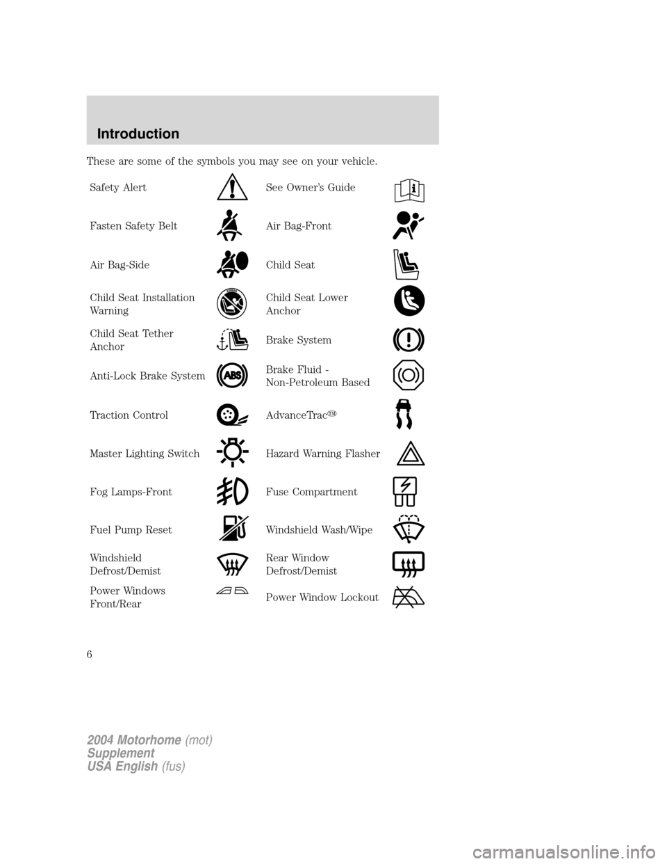
These are some of the symbols you may see on your vehicle.
Safety Alert
See Owner’s Guide
Fasten Safety BeltAir Bag-Front
Air Bag-SideChild Seat
Child Seat Installation
WarningChild Seat Lower
Anchor
Child Seat Tether
AnchorBrake System
Anti-Lock Brake SystemBrake Fluid -
Non-Petroleum Based
Traction ControlAdvanceTrac�
Master Lighting SwitchHazard Warning Flasher
Fog Lamps-FrontFuse Compartment
Fuel Pump ResetWindshield Wash/Wipe
Windshield
Defrost/DemistRear Window
Defrost/Demist
Power Windows
Front/RearPower Window Lockout
2004 Motorhome(mot)
Supplement
USA English(fus)
Introduction
6
Page 10 of 120
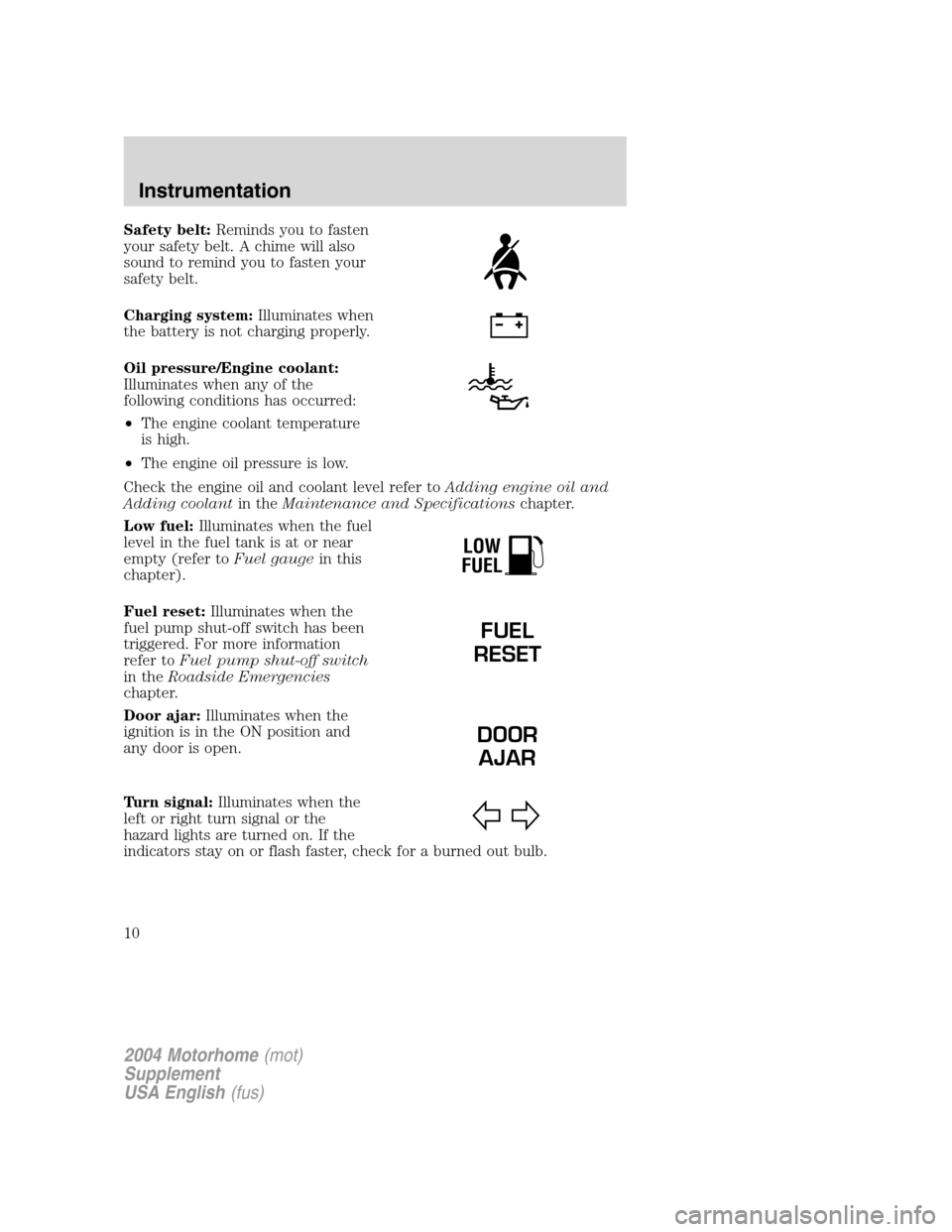
Safety belt:Reminds you to fasten
your safety belt. A chime will also
sound to remind you to fasten your
safety belt.
Charging system:Illuminates when
the battery is not charging properly.
Oil pressure/Engine coolant:
Illuminates when any of the
following conditions has occurred:
•The engine coolant temperature
is high.
•The engine oil pressure is low.
Check the engine oil and coolant level refer toAdding engine oil and
Adding coolantin theMaintenance and Specificationschapter.
Low fuel:Illuminates when the fuel
level in the fuel tank is at or near
empty (refer toFuel gaugein this
chapter).
Fuel reset:Illuminates when the
fuel pump shut-off switch has been
triggered. For more information
refer toFuel pump shut-off switch
in theRoadside Emergencies
chapter.
Door ajar:Illuminates when the
ignition is in the ON position and
any door is open.
Turn signal:Illuminates when the
left or right turn signal or the
hazard lights are turned on. If the
indicators stay on or flash faster, check for a burned out bulb.
LOW
FUEL
FUEL
RESET
DOOR
AJAR
2004 Motorhome(mot)
Supplement
USA English(fus)
Instrumentation
10
Page 40 of 120
HAZARD LIGHTS CONTROL
Use only in an emergency to warn traffic of vehicle breakdown,
approaching danger, etc. The hazard flashers can be operated when the
ignition is off.
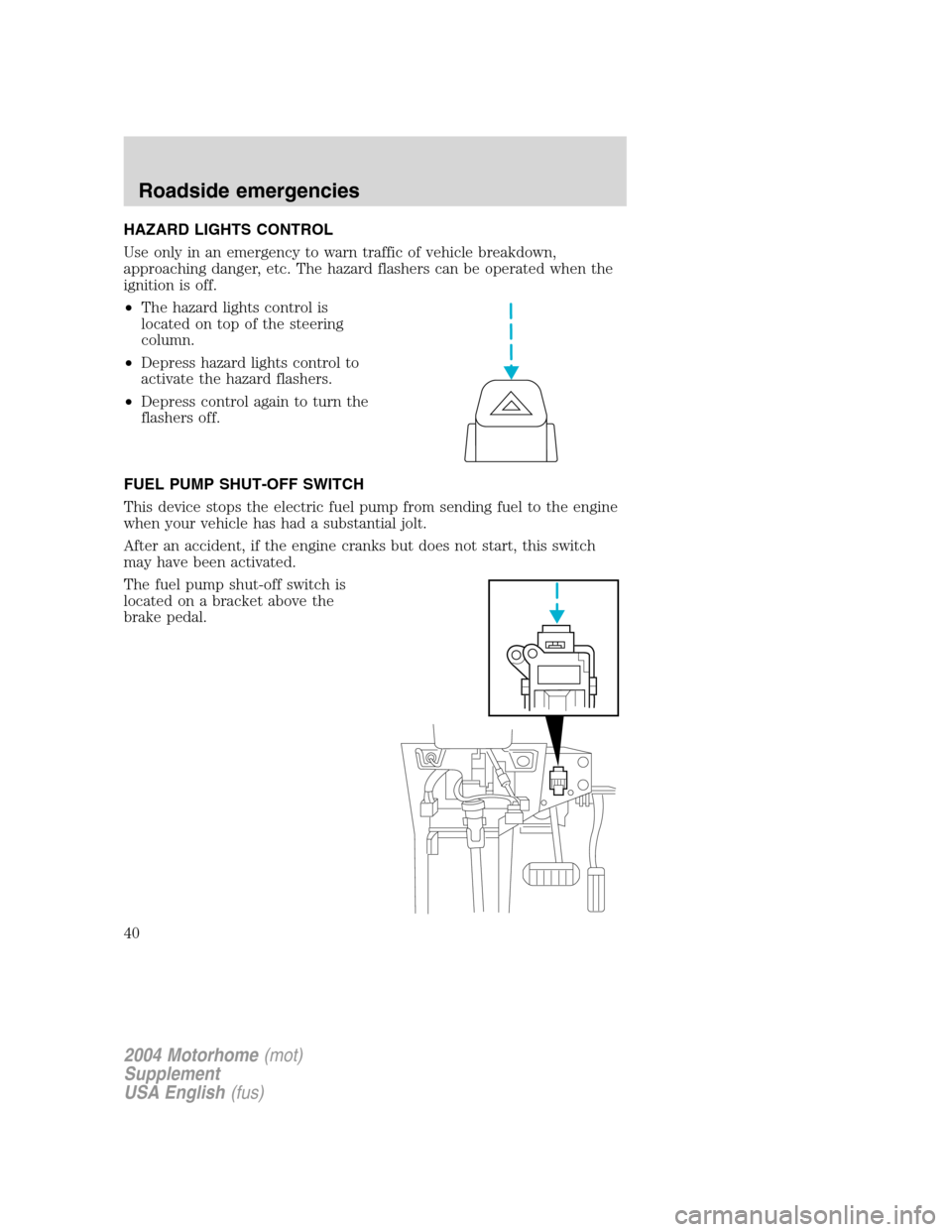
•The hazard lights control is
located on top of the steering
column.
•Depress hazard lights control to
activate the hazard flashers.
•Depress control again to turn the
flashers off.
FUEL PUMP SHUT-OFF SWITCH
This device stops the electric fuel pump from sending fuel to the engine
when your vehicle has had a substantial jolt.
After an accident, if the engine cranks but does not start, this switch
may have been activated.
The fuel pump shut-off switch is
located on a bracket above the
brake pedal.
2004 Motorhome(mot)
Supplement
USA English(fus)
Roadside emergencies
40
Page 41 of 120
Use the following procedure to reset the fuel pump shut-off switch.
1. Turn the ignition to the OFF position.
2. Check the fuel system for leaks.
3. If no fuel leak is apparent, reset the fuel pump shut-off switch by
pushing in on the reset button.
4. Turn the ignition to the ON position. Pause for a few seconds and
return the key to the OFF position.
5. Make a further check for leaks in the fuel system.
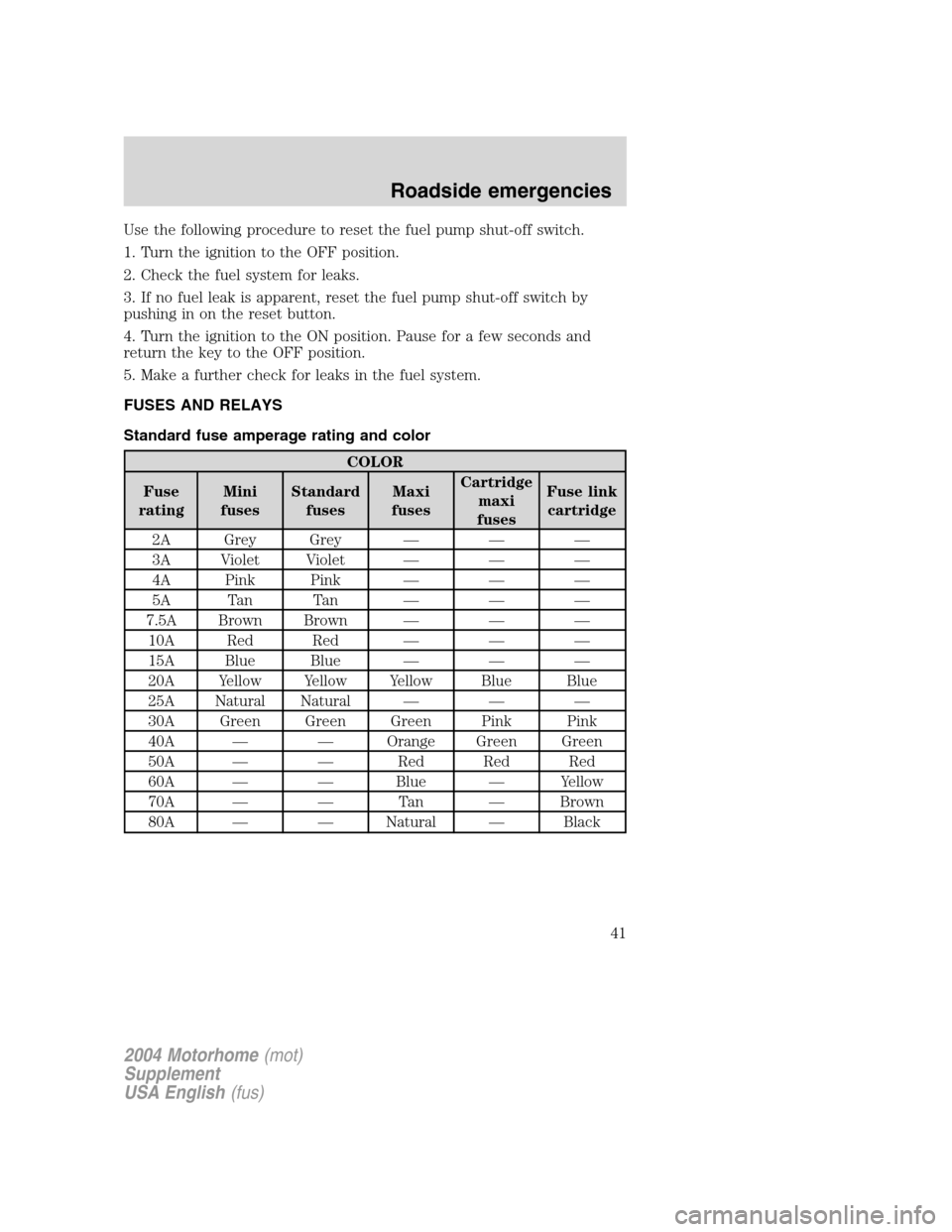
FUSES AND RELAYS
Standard fuse amperage rating and color
COLOR
Fuse
ratingMini
fusesStandard
fusesMaxi
fusesCartridge
maxi
fusesFuse link
cartridge
2A Grey Grey———
3A Violet Violet———
4A Pink Pink———
5A Tan Tan———
7.5A Brown Brown———
10A Red Red———
15A Blue Blue———
20A Yellow Yellow Yellow Blue Blue
25A Natural Natural———
30A Green Green Green Pink Pink
40A——Orange Green Green
50A——Red Red Red
60A——Blue—Yellow
70A——Ta n—Brown
80A——Natural—Black
2004 Motorhome(mot)
Supplement
USA English(fus)
Roadside emergencies
41
Page 46 of 120
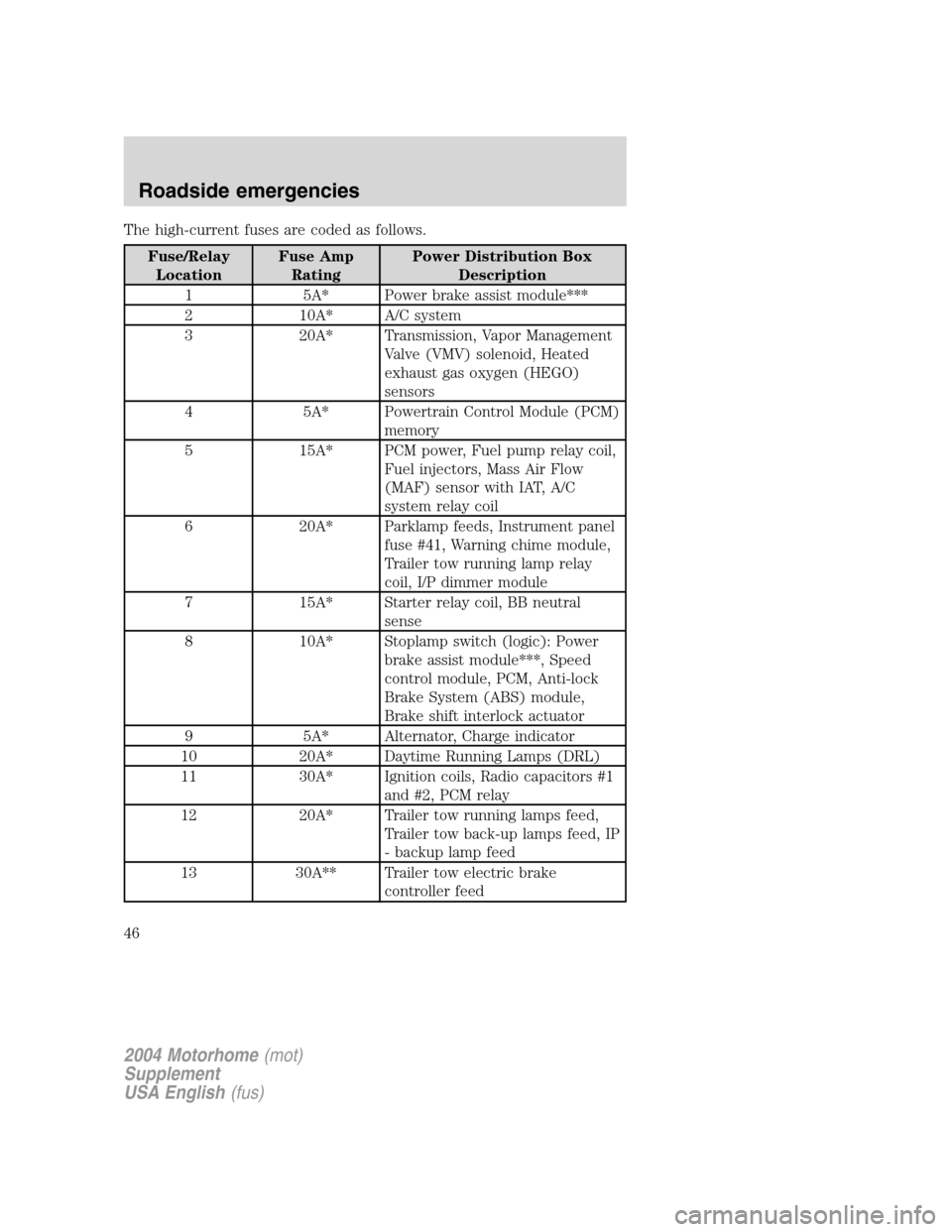
The high-current fuses are coded as follows.
Fuse/Relay
LocationFuse Amp
RatingPower Distribution Box
Description
1 5A* Power brake assist module***
2 10A* A/C system
3 20A* Transmission, Vapor Management
Valve (VMV) solenoid, Heated
exhaust gas oxygen (HEGO)
sensors
4 5A* Powertrain Control Module (PCM)
memory
5 15A* PCM power, Fuel pump relay coil,
Fuel injectors, Mass Air Flow
(MAF) sensor with IAT, A/C
system relay coil
6 20A* Parklamp feeds, Instrument panel
fuse #41, Warning chime module,
Trailer tow running lamp relay
coil, I/P dimmer module
7 15A* Starter relay coil, BB neutral
sense
8 10A* Stoplamp switch (logic): Power
brake assist module***, Speed
control module, PCM, Anti-lock
Brake System (ABS) module,
Brake shift interlock actuator
9 5A* Alternator, Charge indicator
10 20A* Daytime Running Lamps (DRL)
11 30A* Ignition coils, Radio capacitors #1
and #2, PCM relay
12 20A* Trailer tow running lamps feed,
Trailer tow back-up lamps feed, IP
- backup lamp feed
13 30A** Trailer tow electric brake
controller feed
2004 Motorhome(mot)
Supplement
USA English(fus)
Roadside emergencies
46
Page 47 of 120
Fuse/Relay
LocationFuse Amp
RatingPower Distribution Box
Description
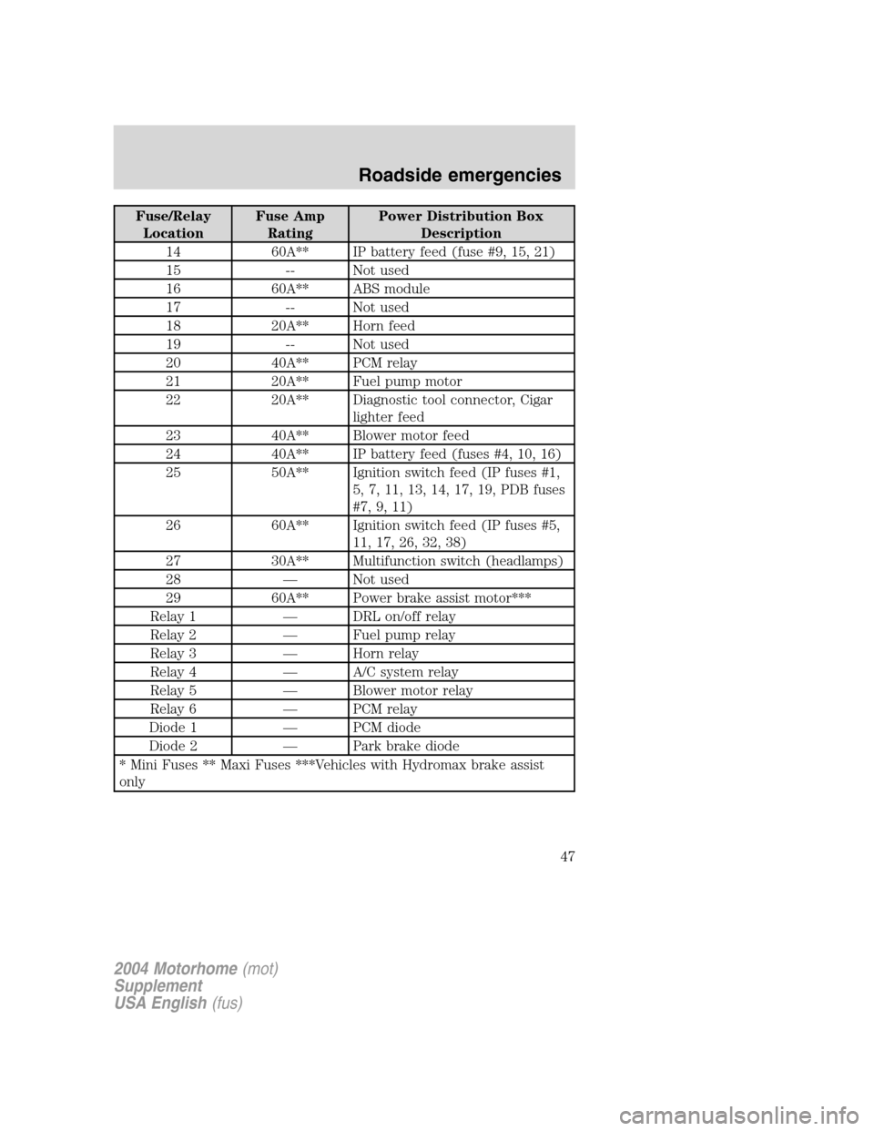
14 60A** IP battery feed (fuse #9, 15, 21)
15 -- Not used
16 60A** ABS module
17 -- Not used
18 20A** Horn feed
19 -- Not used
20 40A** PCM relay
21 20A** Fuel pump motor
22 20A** Diagnostic tool connector, Cigar
lighter feed
23 40A** Blower motor feed
24 40A** IP battery feed (fuses #4, 10, 16)
25 50A** Ignition switch feed (IP fuses #1,
5, 7, 11, 13, 14, 17, 19, PDB fuses
#7, 9, 11)
26 60A** Ignition switch feed (IP fuses #5,
11, 17, 26, 32, 38)
27 30A** Multifunction switch (headlamps)
28—Not used
29 60A** Power brake assist motor***
Relay 1—DRL on/off relay
Relay 2—Fuel pump relay
Relay 3—Horn relay
Relay 4—A/C system relay
Relay 5—Blower motor relay
Relay 6—PCM relay
Diode 1—PCM diode
Diode 2—Park brake diode
* Mini Fuses ** Maxi Fuses ***Vehicles with Hydromax brake assist
only
2004 Motorhome(mot)
Supplement
USA English(fus)
Roadside emergencies
47