Page 84 of 296
Memory seats/adjustable pedals/easy entry-exit feature
(if equipped)
The remote entry system can also control the memory seat /adjustable
pedals/easy entry-exit feature.
Press
to automatically move the seat and adjustable pedals to the
desired memory position (the seat position corresponds to the
transmitter being used).
Activating the memory seat feature
To activate this feature:
1. Position the seat and adjustable pedals to the position desired.
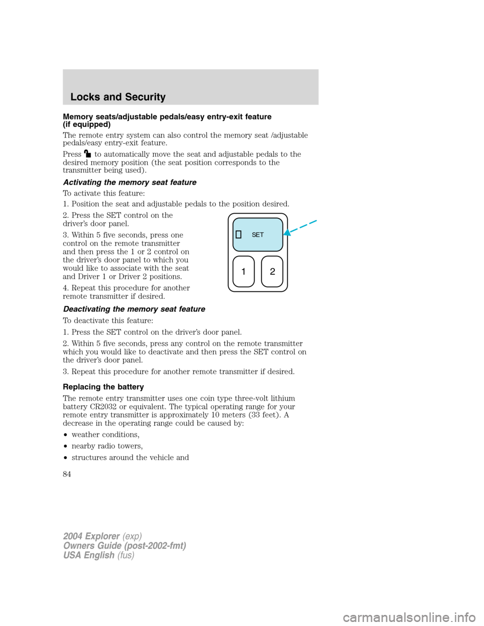
2. Press the SET control on the
driver’s door panel.
3. Within 5 five seconds, press one
control on the remote transmitter
and then press the 1 or 2 control on
the driver’s door panel to which you
would like to associate with the seat
and Driver 1 or Driver 2 positions.
4. Repeat this procedure for another
remote transmitter if desired.
Deactivating the memory seat feature
To deactivate this feature:
1. Press the SET control on the driver’s door panel.
2. Within 5 five seconds, press any control on the remote transmitter
which you would like to deactivate and then press the SET control on
the driver’s door panel.
3. Repeat this procedure for another remote transmitter if desired.
Replacing the battery
The remote entry transmitter uses one coin type three-volt lithium
battery CR2032 or equivalent. The typical operating range for your
remote entry transmitter is approximately 10 meters (33 feet). A
decrease in the operating range could be caused by:
•weather conditions,
•nearby radio towers,
•structures around the vehicle and
SE T
12
2004 Explorer(exp)
Owners Guide (post-2002-fmt)
USA English(fus)
Locks and Security
84
Page 85 of 296
•other vehicles parked next to the vehicle.
To replace the battery:
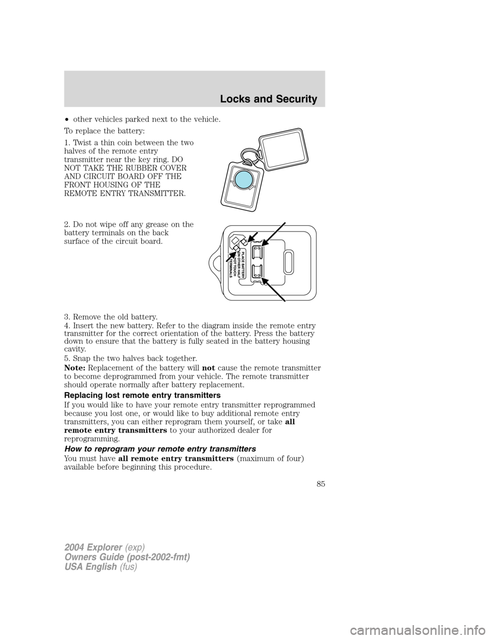
1. Twist a thin coin between the two
halves of the remote entry
transmitter near the key ring. DO
NOT TAKE THE RUBBER COVER
AND CIRCUIT BOARD OFF THE
FRONT HOUSING OF THE
REMOTE ENTRY TRANSMITTER.
2. Do not wipe off any grease on the
battery terminals on the back
surface of the circuit board.
3. Remove the old battery.
4. Insert the new battery. Refer to the diagram inside the remote entry
transmitter for the correct orientation of the battery. Press the battery
down to ensure that the battery is fully seated in the battery housing
cavity.
5. Snap the two halves back together.
Note:Replacement of the battery willnotcause the remote transmitter
to become deprogrammed from your vehicle. The remote transmitter
should operate normally after battery replacement.
Replacing lost remote entry transmitters
If you would like to have your remote entry transmitter reprogrammed
because you lost one, or would like to buy additional remote entry
transmitters, you can either reprogram them yourself, or takeall
remote entry transmittersto your authorized dealer for
reprogramming.
How to reprogram your remote entry transmitters
You must haveall remote entry transmitters(maximum of four)
available before beginning this procedure.
2004 Explorer(exp)
Owners Guide (post-2002-fmt)
USA English(fus)
Locks and Security
85
Page 87 of 296
The inside lights will not turn off if:
•they have been turned on with the dimmer control, or
•any door is open.
The battery saver will shut off the interior lamps 10 minutes after the
ignition has been turned to the OFF position.
KEYLESS ENTRY SYSTEM (IF EQUIPPED)
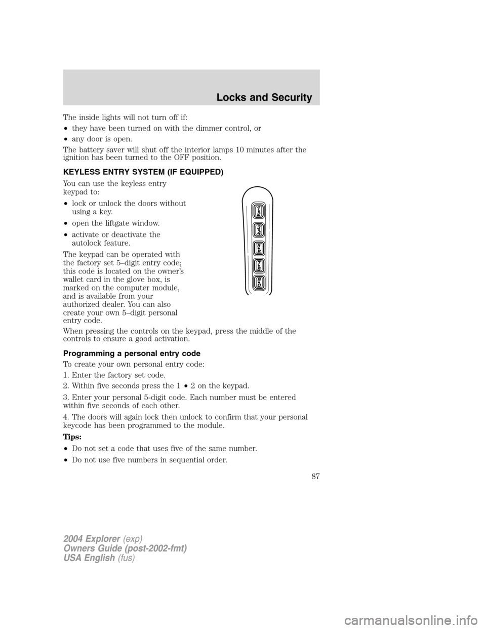
You can use the keyless entry
keypad to:
•lock or unlock the doors without
using a key.
•open the liftgate window.
•activate or deactivate the
autolock feature.
The keypad can be operated with
the factory set 5–digit entry code;
this code is located on the owner’s
wallet card in the glove box, is
marked on the computer module,
and is available from your
authorized dealer. You can also
create your own 5–digit personal
entry code.
When pressing the controls on the keypad, press the middle of the
controls to ensure a good activation.
Programming a personal entry code
To create your own personal entry code:
1. Enter the factory set code.
2. Within five seconds press the 1•2 on the keypad.
3. Enter your personal 5-digit code. Each number must be entered
within five seconds of each other.
4. The doors will again lock then unlock to confirm that your personal
keycode has been programmed to the module.
Tips:
•Do not set a code that uses five of the same number.
•Do not use five numbers in sequential order.
2004 Explorer(exp)
Owners Guide (post-2002-fmt)
USA English(fus)
Locks and Security
87
Page 149 of 296
Always set the parking brake fully and make sure the gearshift is
latched in P (Park). Turn the ignition to the LOCK position and
remove the key whenever you leave your vehicle.
If the parking brake is fully released, but the brake warning lamp
remains illuminated, the brakes may not be working properly.
See your dealer or a qualified service technician.
Driving with a 5–speed automatic transmission
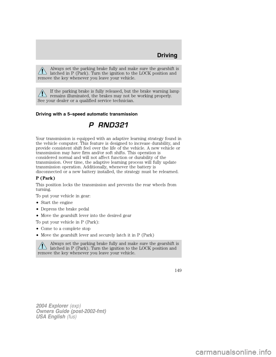
Your transmission is equipped with an adaptive learning strategy found in
the vehicle computer. This feature is designed to increase durability, and
provide consistent shift feel over the life of the vehicle. A new vehicle or
transmission may have firm and/or soft shifts. This operation is
considered normal and will not affect function or durability of the
transmission. Over time, the adaptive learning process will fully update
transmission operation. Additionally, whenever the battery is
disconnected or a new battery installed, the strategy must be relearned.
P (Park)
This position locks the transmission and prevents the rear wheels from
turning.
To put your vehicle in gear:
•Start the engine
•Depress the brake pedal
•Move the gearshift lever into the desired gear
To put your vehicle in P (Park):
•Come to a complete stop
•Move the gearshift lever and securely latch it in P (Park)
Always set the parking brake fully and make sure the gearshift is
latched in P (Park). Turn the ignition to the LOCK position and
remove the key whenever you leave your vehicle.
2004 Explorer(exp)
Owners Guide (post-2002-fmt)
USA English(fus)
Driving
149
Page 182 of 296
Canadian customers who require roadside assistance, call
1–800–665–2006.
If you need to arrange roadside assistance for yourself, Ford Motor
Company will reimburse a reasonable amount. To obtain reimbursement
information, U.S. Ford or Mercury vehicles customers call
1-800-241-3673; Lincoln vehicle customers call 1–800–521–4140.
Canadian customers who need to obtain reimbursement information, call
1–800–665–2006.
ROADSIDE COVERAGE BEYOND BASIC WARRANTY
In the United States, you may purchase additional roadside assistance
coverage beyond this period through the Ford Auto Club by contacting
your Ford or Lincoln Mercury dealer.
Similarly in Canada, for uninterrupted Roadside Assistance coverage, you
may purchase extended coverage prior to your Basic Warranty’s Roadside
Assistance expiring. For more information and enrollment, contact
1–877–294–2582 or visit our website at www.ford.ca.
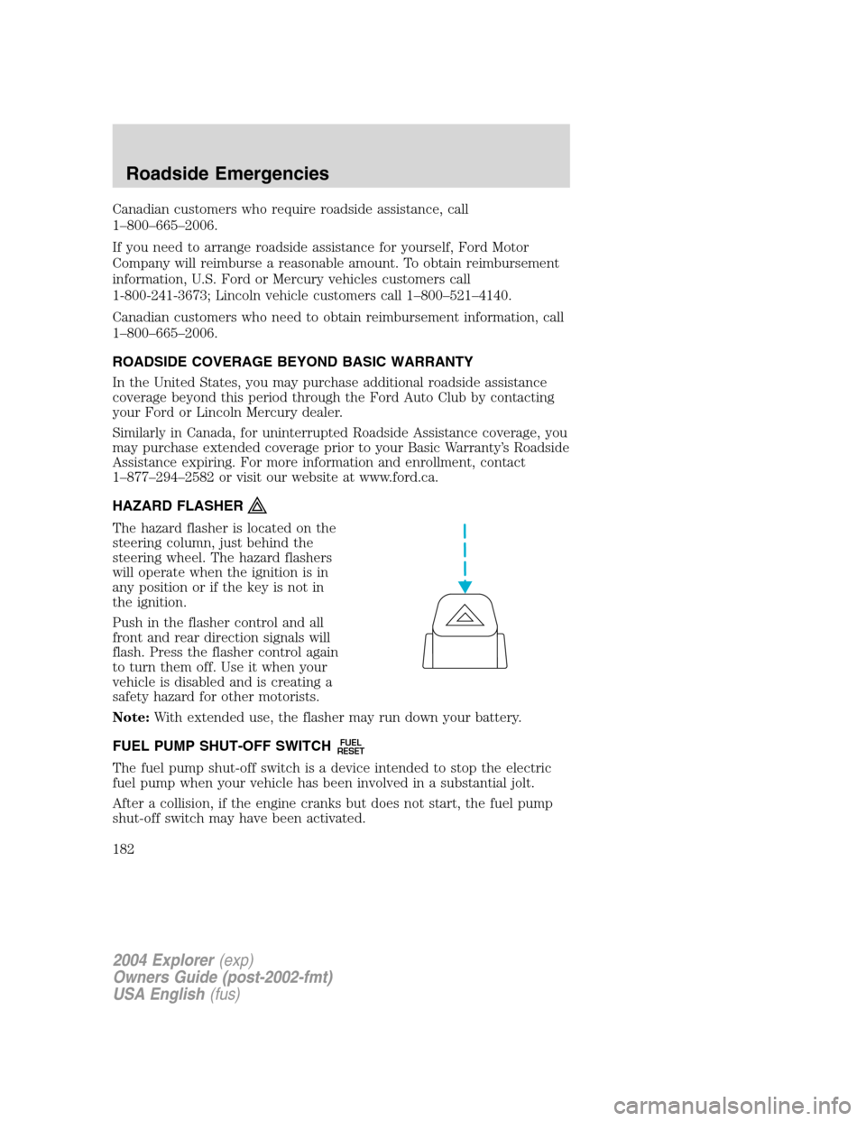
HAZARD FLASHER
The hazard flasher is located on the
steering column, just behind the
steering wheel. The hazard flashers
will operate when the ignition is in
any position or if the key is not in
the ignition.
Push in the flasher control and all
front and rear direction signals will
flash. Press the flasher control again
to turn them off. Use it when your
vehicle is disabled and is creating a
safety hazard for other motorists.
Note:With extended use, the flasher may run down your battery.
FUEL PUMP SHUT-OFF SWITCH
FUEL
RESET
The fuel pump shut-off switch is a device intended to stop the electric
fuel pump when your vehicle has been involved in a substantial jolt.
After a collision, if the engine cranks but does not start, the fuel pump
shut-off switch may have been activated.
2004 Explorer(exp)
Owners Guide (post-2002-fmt)
USA English(fus)
Roadside Emergencies
182
Page 186 of 296
The fuses are coded as follows:
Fuse/Relay
LocationFuse Amp
RatingPassenger Compartment Fuse
Panel Description
1 30A Memory seat module, Driver
power seat
2 20A Moonroof
3 20A Radio, Amplifier, DVD
4 5A Front wiper module
5 15A Flasher relay (Turn, hazards)
6 10A Key-in-chime
7 15A Heated mirrors
8 5A Heated PCV (4.0L engine only)
9 15A Not used
10 10A Heated backlight relay coil, A/C
clutch contact
11 20A Heated seats
12 5A 4x4 (switch)
13 5A Overdrive cancel switch
14 5A PATS
15 5A Rear wiper module, Cluster
16 5A Power mirror, Manual climate
control, TPMS
17 15A Delayed accessory relay
coil/Battery saver coil and
contact/Reading and glove box
lamps
18 10A Flexible fuel pump
19 10A Restraint Control Module (RCM)
20 5A Memory driver seat switch, Driver
seat module, Body Security
Module (BSM), PATS LED
21 5A Instrument cluster, Compass,
Flasher coil
22 10A ABS, IVD Controller
2004 Explorer(exp)
Owners Guide (post-2002-fmt)
USA English(fus)
Roadside Emergencies
186
Page 187 of 296
Fuse/Relay
LocationFuse Amp
RatingPassenger Compartment Fuse
Panel Description
23 15A Not used
24 15A Cigar lighter, OBD II, Neutral tow
25 5A Mode-Temperature actuator for
auxiliary climate control, Trailer
tow battery charge relay coil,
TPMS
26 7.5A Reverse park aid, Brake shift
interlock, IVD switch
27 7.5A Automatic dimming mirror, Digital
transmission range sensor, Backup
lamps
28 5A Radio (Start)
29 10A Digital transmission range sensor,
PWR feed to fuse #28 (Start feed)
30 5A Daytime Running Lamps (DRL),
DEATC climate controller, Manual
climate control, Manual climate
control temp blend actuator
2004 Explorer(exp)
Owners Guide (post-2002-fmt)
USA English(fus)
Roadside Emergencies
187
Page 188 of 296
Passenger compartment fuse panel (top side)
These relays are located on the reverse side of the passenger
compartment fuse panel. See your dealer or a certified technician for
service of this relay box.
Fuse/Relay Location Description
Relay 1 Flasher
Relay 2 Rear defrost
Relay 3 Delayed accessory
Relay 4 Open
Relay 5 Battery saver
Relay 6 Open
Relay 7 Open
2004 Explorer(exp)
Owners Guide (post-2002-fmt)
USA English(fus)
Roadside Emergencies
188