2004 DODGE TOWN AND COUNTRY message center
[x] Cancel search: message centerPage 396 of 2585

(5) Obtain ignition keys to be programmed from
customer (8 keys maximum).
(6) Using the DRB III, erase all ignition keys by
selecting MISCELLANEOUS and ERASE ALL CUR-
RENT IGN. KEYS.
(7) Program all ignition keys.
Learned Key In Ignition - Ignition key transponder
ID is currently programmed in SKIM memory.
BODY CONTROL MODULE
DESCRIPTION
The Body Control Module (BCM) is located in the
passenger compartment, attached to the bulkhead
underneath the left side of the instrument panel.
The BCM utilizes integrated circuitry and informa-
tion carried on the Programmable Communications
Interface (PCI) data bus network along with many
hard wired inputs to monitor many sensor and
switch inputs throughout the vehicle. In response to
those inputs, the internal circuitry and programming
of the BCM allow it to control and integrate many
electronic functions and features of the vehicle
through both hard wired outputs and the transmis-
sion of electronic message outputs to other electronic
modules in the vehicle over the PCI data bus.
OPERATION
The Body Control Module (BCM) supplies vehicle
occupants with visual and audible information and
controls various vehicle functions. To provide and
receive information, the BCM is interfaced to the
vehicle's serial bus communications network, referred
to as the Programmable Communications Interface
(PCI) bus.
This network consists of the;
²Powertrain Control Module (PCM)
²Transmission Control Module (TCM)
²Mechanical Instrument Cluster (MIC)
²Occupant Restraint Controller (ORC)
²Compass/Mini-Trip Computer (CMTC)
²Electronic Vehicle Information Center (EVIC)
²Controller Antilock Brake (CAB)²HVAC Control Module
²Sliding Door Control Modules (driver and pas-
senger side doors)
²Power Liftgate Module (PLG)
²Audio system equipped with RAZ, RBU, RBK,
and RBB radios.
²Side Impact Airbag Control Module (SIACM)
²Memory Seat Module (MSM)
²Sentry Key Immobilizer Module (SKIM)
The BCM is operational when battery power is
supplied to the module.
The BCM provides the following features:
²Power Door Locks
²Automatic Door Locks
²Battery Protection - The BCM will automatically
turn off all exterior lamps after 3 minutes, and all
interior lamps after 15 minutes after the ignition is
turned off, if they are not turned off by the driver.
²Chime Control
²Compass/Mini-Trip support.
²Interior Lighting (Courtesy/Reading Lamps)
²BCM Diagnostic Reporting
²Electronic Liftgate Release (with Power Door
Locks)
²Exterior Lighting
²Headlamp Time Delay (with/without Automatic
Headlamps)
²Illuminated Entry
²Fade to Off Interior Lamps - This feature dims
the interior lighting (courtesy lamps) gradually if the
BCM does not receive any new inputs that would
cause the interior lamps to remain on.
²Pulse Width Modulated Instrument Panel Dim-
ming
²Door Lock Inhibit - This feature disables the
door lock functions if the key is in the ignition and
either front door is ajar. Pressing the Remote Keyless
Entry (RKE) lock/unlock button under these condi-
tions result in normal lock/unlock activation.
The BCM has the ability to LEARN additional fea-
tures in the vehicle, provided the appropriate switch
input and PCI data bus messages are received. Refer
to the LEARNED FEATURES table.
RSELECTRONIC CONTROL MODULES8E-3
ELECTRONIC CONTROL MODULES (Continued)
Page 398 of 2585

(6) Remove the screws holding the BCM to the
bulkhead.
(7) Remove the BCM from the mounting bracket.
INSTALLATION
(1) Install the BCM to the mounting bracket.
(2) Install the screws holding the BCM to the
bulkhead.
(3) Connect the five wire connectors to the bottom
of the Body Control Module (BCM).
(4) Install the knee blocker and reinforcement
(Refer to 23 - BODY/INSTRUMENT PANEL/KNEE
BLOCKER REINFORCEMENT - INSTALLATION).
(5) Install the lower instrument panel silencer.
(6) Connect the battery negative cable.
(7) Verify proper operation of BCM and its func-
tions.
CONTROLLER ANTILOCK
BRAKE
DESCRIPTION
The controller antilock brake (CAB) is a micropro-
cessor-based device which monitors the antilock
brake system (ABS) during normal braking and con-
trols it when the vehicle is in an ABS stop. The CAB
is mounted to the HCU as part of the integrated con-
trol unit (ICU) (Fig. 1). The CAB uses a 24-way elec-
trical connector on the vehicle wiring harness. The
power source for the CAB is through the ignition
switch in the RUN or ON position. The CAB is on
the PCI bus.
OPERATION
The primary functions of the controller antilock
brake (CAB) are to:
²Monitor the antilock brake system for proper
operation.
²Detect wheel locking or wheel slipping tenden-
cies by monitoring the speed of all four wheels of the
vehicle.
²Control fluid modulation to the wheel brakes
while the system is in an ABS mode.
²Store diagnostic information.
²Provide communication to the DRBIIItscan tool
while in diagnostic mode.
²Illuminate the amber ABS warning indicator
lamp.
²(With traction control only) Illuminate the TRAC
ON lamp in the message center on the instrument
panel when a traction control event occurs.
²(with traction control only) Illuminate the TRAC
OFF lamp when the amber ABS warning indicator
lamp illuminates.
The CAB constantly monitors the antilock brake
system for proper operation. If the CAB detects a
fault, it will turn on the amber ABS warning indica-
tor lamp and disable the antilock braking system.
The normal base braking system will remain opera-
tional.
NOTE: If the vehicle is equipped with traction con-
trol, the TRAC OFF lamp will illuminate anytime the
amber ABS warning indicator lamp illuminates.
The CAB continuously monitors the speed of each
wheel through the signals generated by the wheel
speed sensors to determine if any wheel is beginning
to lock. When a wheel locking tendency is detected,
the CAB commands the CAB command coils to actu-
ate. The coils then open and close the valves in the
HCU that modulate brake fluid pressure in some or
all of the hydraulic circuits. The CAB continues to
control pressure in individual hydraulic circuits until
a locking tendency is no longer present.
The CAB contains a self-diagnostic program that
monitors the antilock brake system for system faults.
When a fault is detected, the amber ABS warning
indicator lamp is turned on and the fault diagnostic
trouble code (DTC) is then stored in a diagnostic pro-
gram memory. A latched fault will disable certain
system functionality for the current ignition cycle. An
unlatched fault will disable certain system function-
ality until the fault condition disappears. These
DTC's will remain in the CAB memory even after the
ignition has been turned off. The DTC's can be read
and cleared from the CAB memory by a technician
using the DRBIIItscan tool. If not cleared with a
DRBIIItscan tool, the fault occurrence and DTC will
Fig. 1 Integrated Control Unit (ICU)
1 - PUMP/MOTOR
2 - HCU
3 - PUMP/MOTOR CONNECTOR
4 - CAB
RSELECTRONIC CONTROL MODULES8E-5
BODY CONTROL MODULE (Continued)
Page 400 of 2585
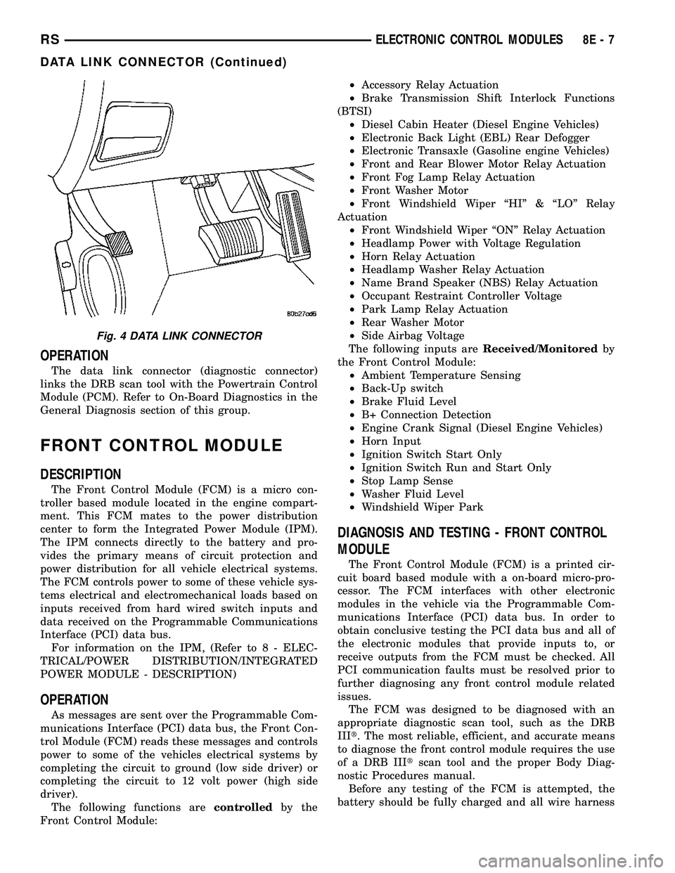
OPERATION
The data link connector (diagnostic connector)
links the DRB scan tool with the Powertrain Control
Module (PCM). Refer to On-Board Diagnostics in the
General Diagnosis section of this group.
FRONT CONTROL MODULE
DESCRIPTION
The Front Control Module (FCM) is a micro con-
troller based module located in the engine compart-
ment. This FCM mates to the power distribution
center to form the Integrated Power Module (IPM).
The IPM connects directly to the battery and pro-
vides the primary means of circuit protection and
power distribution for all vehicle electrical systems.
The FCM controls power to some of these vehicle sys-
tems electrical and electromechanical loads based on
inputs received from hard wired switch inputs and
data received on the Programmable Communications
Interface (PCI) data bus.
For information on the IPM, (Refer to 8 - ELEC-
TRICAL/POWER DISTRIBUTION/INTEGRATED
POWER MODULE - DESCRIPTION)
OPERATION
As messages are sent over the Programmable Com-
munications Interface (PCI) data bus, the Front Con-
trol Module (FCM) reads these messages and controls
power to some of the vehicles electrical systems by
completing the circuit to ground (low side driver) or
completing the circuit to 12 volt power (high side
driver).
The following functions arecontrolledby the
Front Control Module:²Accessory Relay Actuation
²Brake Transmission Shift Interlock Functions
(BTSI)
²Diesel Cabin Heater (Diesel Engine Vehicles)
²Electronic Back Light (EBL) Rear Defogger
²Electronic Transaxle (Gasoline engine Vehicles)
²Front and Rear Blower Motor Relay Actuation
²Front Fog Lamp Relay Actuation
²Front Washer Motor
²Front Windshield Wiper ªHIº & ªLOº Relay
Actuation
²Front Windshield Wiper ªONº Relay Actuation
²Headlamp Power with Voltage Regulation
²Horn Relay Actuation
²Headlamp Washer Relay Actuation
²Name Brand Speaker (NBS) Relay Actuation
²Occupant Restraint Controller Voltage
²Park Lamp Relay Actuation
²Rear Washer Motor
²Side Airbag Voltage
The following inputs areReceived/Monitoredby
the Front Control Module:
²Ambient Temperature Sensing
²Back-Up switch
²Brake Fluid Level
²B+ Connection Detection
²Engine Crank Signal (Diesel Engine Vehicles)
²Horn Input
²Ignition Switch Start Only
²Ignition Switch Run and Start Only
²Stop Lamp Sense
²Washer Fluid Level
²Windshield Wiper Park
DIAGNOSIS AND TESTING - FRONT CONTROL
MODULE
The Front Control Module (FCM) is a printed cir-
cuit board based module with a on-board micro-pro-
cessor. The FCM interfaces with other electronic
modules in the vehicle via the Programmable Com-
munications Interface (PCI) data bus. In order to
obtain conclusive testing the PCI data bus and all of
the electronic modules that provide inputs to, or
receive outputs from the FCM must be checked. All
PCI communication faults must be resolved prior to
further diagnosing any front control module related
issues.
The FCM was designed to be diagnosed with an
appropriate diagnostic scan tool, such as the DRB
IIIt. The most reliable, efficient, and accurate means
to diagnose the front control module requires the use
of a DRB IIItscan tool and the proper Body Diag-
nostic Procedures manual.
Before any testing of the FCM is attempted, the
battery should be fully charged and all wire harness
Fig. 4 DATA LINK CONNECTOR
RSELECTRONIC CONTROL MODULES8E-7
DATA LINK CONNECTOR (Continued)
Page 418 of 2585
BODY CONTROL MODULE
TABLE OF CONTENTS
page page
BODY CONTROL MODULE DESCRIPTION ..........................1
OPERATION ............................1 REMOVAL
.............................3
INSTALLATION ..........................3
BODY CONTROL MODULE
DESCRIPTION
The Body Control Module (BCM) is located in the
passenger compartment, attached to the bulkhead
underneath the left side of the instrument panel. The BCM utilizes integrated circuitry and informa-
tion carried on the Programmable Communications
Interface (PCI) data bus network along with many
hard wired inputs to monitor many sensor and
switch inputs throughout the vehicle. In response to
those inputs, the internal circuitry and programming
of the BCM allow it to control and integrate many
electronic functions and features of the vehicle
through both hard wired outputs and the transmis-
sion of electronic message outputs to other electronic
modules in the vehicle over the PCI data bus.
OPERATION
The Body Control Module (BCM) supplies vehicle
occupants with visual and audible information and
controls various vehicle functions. To provide and
receive information, the BCM is interfaced to the
vehicle's serial bus communications network, referred
to as the Programmable Communications Interface
(PCI) bus. This network consists of the;
² Powertrain Control Module (PCM)
² Transmission Control Module (TCM)
² Mechanical Instrument Cluster (MIC)
² Occupant Restraint Controller (ORC)
² Compass/Mini-Trip Computer (CMTC)
² Electronic Vehicle Information Center (EVIC)
² Controller Antilock Brake (CAB)
² HVAC Control Module
² Sliding Door Control Modules (driver and pas-
senger side doors) ² Power Liftgate Module (PLG) ²
Audio system equipped with RAZ, RBU, RBK,
and RBB radios. ² Sentry Key Remote Entry Module (SKREEM).
² Side Impact Airbag Control Module (SIACM)
² Memory Seat Module (MSM)
² Sentry Key Immobilizer Module (SKIM)
The BCM is operational when battery power is
supplied to the module. The BCM provides the following features:
² Power Door Locks
² Automatic Door Locks
² Battery Protection - The BCM will automatically
turn off all exterior lamps after 3 minutes, and all
interior lamps after 15 minutes after the ignition is
turned off, if they are not turned off by the driver. ² Chime Control
² Compass/Mini-Trip support.
² Interior Lighting (Courtesy/Reading Lamps)
² BCM Diagnostic Reporting
² Electronic Liftgate Release (with Power Door
Locks) ² Exterior Lighting
² Headlamp Time Delay (with/without Automatic
Headlamps) ² Illuminated Entry
² Fade to Off Interior Lamps - This feature dims
the interior lighting (courtesy lamps) gradually if the
BCM does not receive any new inputs that would
cause the interior lamps to remain on. ² Pulse Width Modulated Instrument Panel Dim-
ming ² Door Lock Inhibit - This feature disables the
door lock functions if the key is in the ignition and
either front door is ajar. Pressing the Remote Keyless
Entry (RKE) lock/unlock button under these condi-
tions result in normal lock/unlock activation. The BCM has the ability to LEARN additional fea-
tures in the vehicle, provided the appropriate switch
input and PCI data bus messages are received. Refer
to the LEARNED FEATURES table.
RS BODY CONTROL MODULE8Es-1
Page 503 of 2585

Refer to the description of the heated seat switch
later in this section for additional information.
Hard wired circuitry connects the heated seat sys-
tem components to each other through the electrical
system of the vehicle. These hard wired circuits are
integral to several wire harnesses, which are routed
throughout the vehicle and retained by many differ-
ent methods. These circuits may be connected to each
other, to the vehicle electrical system and to the
heated seat system components through the use of a
combination of soldered splices and splice block con-
nectors. Refer to Wiring for complete system wiring
schematics. The wiring information also includes the
proper wire and connector repair procedures, further
details on wire harness routing and retention, as well
as pin-out and location views for the various wire
harness connectors, splices and grounds.
OPERATION
The heated seat system components operate on
battery current received through a fuse in the Inte-
grated Power Module (IPM) on a fused ignition
switch output (run) circuit from the Body Control
Module. The system will only operate when the igni-
tion switch is in the On position. The heated seat
system will be turned Off automatically whenever
the ignition switch is turned to any position except
On. Also, the heated seat system will not operate
when the surface temperature of the seat cushion
cover at either heated seat sensor is above the
designed temperature set points of the system. See
the owner's manual in the vehicle glove box for more
information on the features, use and operation of the
heated seat system.
DIAGNOSIS AND TESTING - HEATED SEAT
SYSTEM
The most reliable, efficient, and accurate means to
diagnose the heated seat system requires the use of a
DRBIIItscan tool and the proper Diagnostic Proce-
dures manual. The DRBIIItscan tool can provide
confirmation that the PCI data bus is functional, that
all of the electronic modules are sending and receiv-
ing the proper messages on the PCI data bus, and
that the heated seat modules are receiving the
proper hard wired inputs from and relaying the
proper hard wired outputs to the Body Control Mod-
ule in order to perform its functions. Refer toWiring
Diagramsfor complete wiring schematics. The wir-
ing information also includes the proper wire and
connector repair procedures, further details on wire
harness routing and retention, as well as pin-out and
location views for the various wire harness connec-
tors, splices and grounds.
DRIVER HEATED SEAT
SWITCH
DESCRIPTION
The heated seat switches are mounted in the
instrument panel center bezel (Fig. 2). The two three-
position rocker-type switches, one switch for each
front seat, are incorporated into one large switch
assembly that also includes the hazard, rear window
wiper and washer switches. The heated seat switches
each provide a resistor multiplexed signal to its
respective Heated Seat Module (HSM) through sepa-
rate hard wired circuits. Each switch has an Off,
Low, and High position so that both the driver and
the front seat passenger can select a preferred seat
heating mode. Each switch has two Light-Emitting
Diodes (LED) which light to indicate that the heater
for the seat is turned on.
The heated seat switches and their LEDs cannot
be repaired. If either switch or LED is faulty or dam-
aged, the entire switch assembly must be replaced.
OPERATION
There are three positions that can be selected with
each of the heated seat switches: Off, Low, or High.
When the left side of the switch rocker is fully
depressed, the Low position is selected and the low
position LED indicator illuminates. When the right
side of the switch rocker is fully depressed, the High
position is selected and the high position LED indi-
Fig. 2 HEATED SEAT SWITCH LOCATION
1 - HEATED SEAT SWITCHES
8G - 8 HEATED SEAT SYSTEMRS
HEATED SEAT SYSTEM (Continued)
Page 504 of 2585
cator illuminates. When the switch rocker is moved
to its neutral position (middle), Off is selected and
both LED indicators are extinguished.
Each switch provides separate resistor multiplexed
hard wire inputs to its respective Heated Seat Mod-
ule (HSM) to indicate the selected switch position.
The heated seat module responds to the heated seat
switch status messages by controlling the output to
the seat heater elements of the selected seat. The
Low heat position set point is about 36É C (97É F),
and the High heat position set point is about 41É C
(105É F).
DIAGNOSIS AND TESTING - DRIVER HEATED
SEAT SWITCH
For complete circuit diagrams, refer toWiring
Diagrams.
WARNING: REFER TO THE RESTRAINTS SECTION
OF THIS MANUAL BEFORE ATTEMPTING ANY
STEERING WHEEL, STEERING COLUMN, SEAT OR
INSTRUMENT PANEL COMPONENT DIAGNOSIS OR
SERVICE. FAILURE TO TAKE THE PROPER PRE-
CAUTIONS COULD RESULT IN ACCIDENTAL AIR-
BAG DEPLOYMENT AND POSSIBLE PERSONAL
INJURY.
CHECKING SWITCH SIGNAL AND WIRING AT THE
MODULE
(1) Disconnect and isolate the battery negative
cable.
(2) Access and disconnect the gray 4-way connector
from the heated seat module. Visually inspect wiring
terminals for damage that would prevent positive
connection. If not OK, repair or replace the necessary
components.
(3) Place the heated seat switch in the LO posi-
tion. Using an Ohmmeter, check the resistance
between cavities 2 and 3 of the gray connector noted
above. Resistance should be about 3.5 kilohms (3500
ohms). If not OK, check resistance directly at switch,
as noted below. If OK, proceed to the next step. If not
OK, replace the faulty switch.
(4) Place the heated seat switch in the HI position.
Using an ohmmeter, check the resistance between
cavities 2 and 3 of the gray connector noted above.
Resistance should be about 1.4 kilohms (1400 ohms).
If not OK, check resistance directly at switch, as
noted below. If OK, proceed. If not OK replace the
faulty switch.
(5) With the system ON in the HI position, check
for battery voltage and ground at cavities 4 and 1. If
OK, proceed with testing remaining components. If
not OK, repair open or shorted wiring.
CHECKING SWITCH ONLY
(1) Disconnect and isolate the battery negative
cable. Remove the center bezel from the instrument
panel (Refer to 23 - BODY/INSTRUMENT PANEL/
INSTRUMENT PANEL CENTER BEZEL -
REMOVAL). Check for continuity between the
ground circuit cavity (#10) of the instrument panel
switch bank electrical connector and a good ground.
There should be continuity. If OK, go to Step 2. If not
OK, repair the open ground circuit to ground as
required.
(2) Reconnect the battery negative cable. Turn the
ignition switch to the On position. Check for battery
voltage at the fused ignition switch output (run) cir-
cuit cavity of the instrument panel switch bank con-
nector (#4). If OK, turn the ignition switch to the Off
position, and go to Step 3. If not OK, repair the open
fused ignition switch output (run) circuit as required.
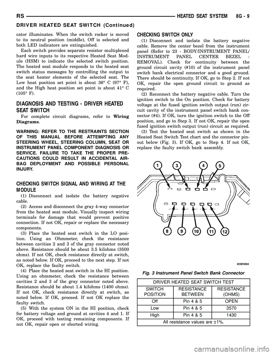
(3) Test the heated seat switch as shown in the
Heated Seat Switch Test chart and the connector pin-
out below (Fig. 3). If OK, go to Step 4. If not OK,
replace the faulty switch bank assembly.
DRIVER HEATED SEAT SWITCH TEST
SWITCH
POSITIONRESISTANCE
BETWEENRESISTANCE
(OHMS)
Off Pin4&5OPEN
Low Pin4&53570
High Pin4&51430
All resistance values are 1%.
Fig. 3 Instrument Panel Switch Bank Connector
RSHEATED SEAT SYSTEM8G-9
DRIVER HEATED SEAT SWITCH (Continued)
Page 507 of 2585

(3) Connect the negative battery cable.
(4) Verify heated seat system operation.
(5) Install the appropriate seat cushion or seat
back trim cover. Make certain the seat wire harness
is correctly routed through the seat and seat back.
The excess wire between the cushion and back ele-
ments should be securely tucked between the rear of
the cushion foam and the rear carpet flap of the trim
cover.
HEATED SEAT SENSOR
DESCRIPTION
Two heated seat sensors are used per vehicle, one
in each front seat cushion heating element. The
heated seat temperature sensor is a Negative Tem-
perature Coefficient (NTC) thermistor.
The heated seat sensors cannot be repaired or
adjusted and if found to be faulty, the complete
heated seat cushion element must be replaced.
OPERATION
The temperature sensor is a NTC thermistor.
When the temperature of the seat cushion cover
rises, the resistance of the sensor decreases. The
heated seat module supplies a five-volt current to one
side of each sensor, and monitors the voltage drop
through the sensor on a return circuit. The heated
seat module uses this temperature sensor input to
monitor the temperature of the seat, and regulates
the current flow to the seat heating elements accord-
ingly.
DIAGNOSIS AND TESTING - HEATED SEAT
SENSOR
For complete circuit diagrams, refer toWiring
Diagrams.
(1) Disconnect and isolate the battery negative
cable. Disconnect the green 4-way heated seat mod-
ule wire harness connector.
(2) Using an ohmmeter, check the resistance
between cavities 2 and 3. The sensor resistance
should be between 50 kilohms at 15É C (60É F) and 2
kilohms at 30É C (85É F). If not OK, replace the
faulty seat element and sensor assembly.
PASSENGER HEATED SEAT
SWITCH
DESCRIPTION
The heated seat switches are mounted in the
instrument panel center bezel (Fig. 6). The two three-
position rocker-type switches, one switch for each
front seat, are incorporated into one large switchassembly that also includes the hazard, rear window
wiper and washer switches. The heated seat switches
each provide a resistor multiplexed signal to its
respective Heated Seat Module (HSM) through sepa-
rate hard wired circuits. Each switch has an Off,
Low, and High position so that both the driver and
the front seat passenger can select a preferred seat
heating mode. Each switch has two Light-Emitting
Diodes (LED) which light to indicate that the heater
for the seat is turned on.
The heated seat switches and their LEDs cannot
be repaired. If either switch or LED is faulty or dam-
aged, the entire switch assembly must be replaced.
OPERATION
There are three positions that can be selected with
each of the heated seat switches: Off, Low, or High.
When the left side of the switch rocker is fully
depressed, the Low position is selected and the low
position LED indicator illuminates. When the right
side of the switch rocker is fully depressed, the High
position is selected and the high position LED indi-
cator illuminates. When the switch rocker is moved
to its neutral position (middle), Off is selected and
both LED indicators are extinguished.
Each switch provides separate resistor multiplexed
hard wire inputs to its respective Heated Seat Mod-
ule (HSM) to indicate the selected switch position.
The heated seat module responds to the heated seat
switch status messages by controlling the output to
the seat heater elements of the selected seat. The
Fig. 6 HEATED SEAT SWITCH LOCATION
1 - HEATED SEAT SWITCHES
8G - 12 HEATED SEAT SYSTEMRS
HEATED SEAT ELEMENTS (Continued)
Page 526 of 2585

INSTRUMENT CLUSTER
TABLE OF CONTENTS
page page
INSTRUMENT CLUSTER
DESCRIPTION..........................1
OPERATION............................1
DIAGNOSIS AND TESTING
DIAGNOSIS AND TESTING - SELF-
DIAGNOSTICS.........................2
DIAGNOSIS AND TESTING - CLUSTER
DIAGNOSIS...........................2REMOVAL.............................10
INSTALLATION.........................10
CLUSTER LENS
REMOVAL.............................10
INSTALLATION.........................10
INSTRUMENT CLUSTER
DESCRIPTION
The instrumentation gauges are contained in a
subdial assembly within the instrument cluster. The
individual gauges are not serviceable. If one of the
cluster gauges becomes faulty, the entire cluster
would require replacement.
The Mechanical Instrument Cluster (MIC) with a
tachometer is equipped with a electronic vacuum flu-
orescent transmission range indicator (PRND3L),
odometer, and trip odometer display.
The MIC without a tachometer is equipped with a
Light Emitting Diode (LED) transmission range indi-
cator (PRND3L) and a vacuum fluorescent odometer
display.
The MIC is equipped with the following warning
lamps.
²Lift Gate Ajar
²Low Fuel Level
²Low Windshield Washer Fluid Level
²Cruise
²Battery Voltage
²Fasten Seat Belt
²Door Ajar
²Coolant Temperature
²Anti-Lock Brake
²Brake
²Oil Pressure
²MIL (Malfunction Indicator Lamp)
²VTSS/SKIS Indicator
²Airbag
²Traction Control
²Autostick
The MIC without a tachometer also has the follow-
ing warning lamps:
²Turns Signals
²High Beam
WATER IN FUEL LAMP - EXPORT
The Water In Fuel Lamp is located in the message
center. When moisture is found within the fuel sys-
tem, the sensor sends a message via the PCI data
bus to the instrument cluster. The MIC illuminates
the bulb in the message center, The sensor is located
underneath the vehicle, directly above the rear axle.
The sensor is housed within the fuel filter/water sep-
arator assembly cover. The sensor is not serviced sep-
arately. If found defective, the entire assembly cover
must be replaced.
OPERATION
Refer to the vehicle Owner's Manual for operation
instructions and conditions for the Instrument Clus-
ter Gauges.
WATER IN FUEL LAMP - EXPORT
The Water In Fuel Sensor is a resistive type
switch. It is calibrated to sense the different resis-
tance between diesel fuel and water. When water
enters the fuel system, it is caught in the bottom of
the fuel filter/water separator assembly, where the
sensor is located. Water has less resistance than die-
sel fuel. The sensor then sends a PCI data bus mes-
sage to the instrument cluster to illuminate the
lamp.
If the lamp is inoperative, perform the self diag-
nostic test on the instrument cluster to check the
lamp operation before continuing diagnosis.
RSINSTRUMENT CLUSTER8J-1