2004 DODGE TOWN AND COUNTRY drain
[x] Cancel search: drainPage 16 of 2585
LUBRICANTS AND GREASES
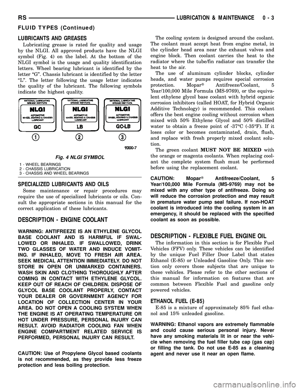
Lubricating grease is rated for quality and usage
by the NLGI. All approved products have the NLGI
symbol (Fig. 4) on the label. At the bottom of the
NLGI symbol is the usage and quality identification
letters. Wheel bearing lubricant is identified by the
letter ªGº. Chassis lubricant is identified by the letter
ªLº. The letter following the usage letter indicates
the quality of the lubricant. The following symbols
indicate the highest quality.
SPECIALIZED LUBRICANTS AND OILS
Some maintenance or repair procedures may
require the use of specialized lubricants or oils. Con-
sult the appropriate sections in this manual for the
correct application of these lubricants.
DESCRIPTION - ENGINE COOLANT
WARNING: ANTIFREEZE IS AN ETHYLENE GLYCOL
BASE COOLANT AND IS HARMFUL IF SWAL-
LOWED OR INHALED. IF SWALLOWED, DRINK
TWO GLASSES OF WATER AND INDUCE VOMIT-
ING. IF INHALED, MOVE TO FRESH AIR AREA.
SEEK MEDICAL ATTENTION IMMEDIATELY. DO NOT
STORE IN OPEN OR UNMARKED CONTAINERS.
WASH SKIN AND CLOTHING THOROUGHLY AFTER
COMING IN CONTACT WITH ETHYLENE GLYCOL.
KEEP OUT OF REACH OF CHILDREN. DISPOSE OF
GLYCOL BASE COOLANT PROPERLY, CONTACT
YOUR DEALER OR GOVERNMENT AGENCY FOR
LOCATION OF COLLECTION CENTER IN YOUR
AREA. DO NOT OPEN A COOLING SYSTEM WHEN
THE ENGINE IS AT OPERATING TEMPERATURE OR
HOT UNDER PRESSURE, PERSONAL INJURY CAN
RESULT. AVOID RADIATOR COOLING FAN WHEN
ENGINE COMPARTMENT RELATED SERVICE IS
PERFORMED, PERSONAL INJURY CAN RESULT.
CAUTION: Use of Propylene Glycol based coolants
is not recommended, as they provide less freeze
protection and less boiling protection.The cooling system is designed around the coolant.
The coolant must accept heat from engine metal, in
the cylinder head area near the exhaust valves and
engine block. Then coolant carries the heat to the
radiator where the tube/fin radiator can transfer the
heat to the air.
The use of aluminum cylinder blocks, cylinder
heads, and water pumps requires special corrosion
protection. MopartAntifreeze/Coolant, 5
Year/100,000 Mile Formula (MS-9769), or the equiva-
lent ethylene glycol base coolant with hybrid organic
corrosion inhibitors (called HOAT, for Hybrid Organic
Additive Technology) is recommended. This coolant
offers the best engine cooling without corrosion when
mixed with 50% Ethylene Glycol and 50% distilled
water to obtain a freeze point of -37ÉC (-35ÉF). If it
loses color or becomes contaminated, drain, flush,
and replace with fresh properly mixed coolant solu-
tion.
The green coolantMUST NOT BE MIXEDwith
the orange or magenta coolants. When replacing cool-
ant the complete system flush must be performed
before using the replacement coolant.
CAUTION: MoparTAntifreeze/Coolant, 5
Year/100,000 Mile Formula (MS-9769) may not be
mixed with any other type of antifreeze. Doing so
will reduce the corrosion protection and may result
in premature water pump seal failure. If non-HOAT
coolant is introduced into the cooling system in an
emergency, it should be replaced with the specified
coolant as soon as possible.
DESCRIPTION - FLEXIBLE FUEL ENGINE OIL
The information in this section is for Flexible Fuel
Vehicles (FFV) only. These vehicles can be identified
by the unique Fuel Filler Door Label that states
Ethanol (E-85) or Unleaded Gasoline Only. This sec-
tion only covers those subjects that are unique to
these vehicles. Please refer to the other sections of
this manual for information on features that are
common between Flexible Fuel and gasoline only
powered vehicles.
ETHANOL FUEL (E-85)
E-85 is a mixture of approximately 85% fuel etha-
nol and 15% unleaded gasoline.
WARNING: Ethanol vapors are extremely flammable
and could cause serious personal injury. Never
have any smoking materials lit in or near the vehi-
cle when removing the fuel filler tube cap (gas cap)
or filling the tank. Do not use E-85 as a cleaning
agent and never use it near an open flame.
Fig. 4 NLGI SYMBOL
1 - WHEEL BEARINGS
2 - CHASSIS LUBRICATION
3 - CHASSIS AND WHEEL BEARINGS
RSLUBRICATION & MAINTENANCE0-3
FLUID TYPES (Continued)
Page 19 of 2585
NOTE: Intentional tampering with emissions control
systems can result in civil penalties being assessed
against you.
DESCRIPTION - FUEL REQUIREMENTS -
DIESEL ENGINE
WARNING: DO NOT USE ALCOHOL OR GASOLINE
AS A FUEL BLENDING AGENT. THEY CAN BE
UNSTABLE UNDER CERTAIN CONDITIONS AND
HAZARDOUS OR EXPLOSIVE WHEN MIXED WITH
DIESEL FUEL.
Use good quality diesel fuel from a reputable sup-
plier. For most year-round service, number 2 diesel
fuel meeting DIN EN 590 (Class0-4)will provide
good performance. If the vehicle is exposed to
extreme cold (below -18ÉC/0ÉF) or is required to oper-
ate at colder than normal conditions for prolonged
periods, use climatize No. 2 diesel fuel or dilute the
No. 2 diesel fuel with 50% No. 1 diesel fuel as long as
it meets ASTM D 975: 1D and 2D and the quality of
lubrication behavior is in accordance with DIN EN
590. This will provide better protection from fuel gel-
ling or wax plugging of the fuel filters.
Diesel fuel is seldom completely free of water. To
prevent fuel system trouble, including fuel line freez-
ing in winter, drain the accumulated water from the
fuel/water separator using the fuel/water separator
drain provided. If you buy good quality fuel and fol-
low the cold weather advice above, fuel conditioners
should not be required in your vehicle. If available in
your area, a high cetane ªpremiumº diesel fuel may
offer improved cold starting and warm up perfor-
mance.
DESCRIPTION - ENGINE OIL - DIESEL
ENGINES
Use only Diesel Engine Oil meeting standardMIL-
2104Cor API ClassificationCD or higherorCCML
D4, D5.
SAE VISCOSITY GRADE
CAUTION: Low viscosity oils must have the proper
API quality or the CCMC G5 designation.
To assure of properly formulated engine oils, it is
recommended that SAE Grade 10W-40 engine oils
that meet Chrysler material standard MS-6395, be
used in accordance to ACEA B3, B4 specification.
European Grade 10W-40 oils are also acceptable.
Oils of the SAE 5W-40 grade number are preferred
when minimum temperatures consistently fall below
-15ÉC.
DESCRIPTION - AWD REAR DRIVELINE
MODULE FLUIDS
The AWD Rear Driveline Module Assembly consists
of two subassemblies, the Overrunning Clutch Hous-
ing (front) and the Differential Carrier (rear).
The recommended lubricant for the Overrunning
Clutch Housing is MopartATF+4. The recommended
lubricant for the Differential Carrier is Mopart
80W-90 Gear and Axle Lubricant.
DESCRIPTION - AWD POWER TRANSFER UNIT
FLUID
The recommended lubricant for the AWD Power
Transfer Unit is MopartGear and Axle Lubricant
80W-90.
FLUID CAPACITIES
SPECIFICATIONS - FLUID CAPACITIES
DESCRIPTION SPECIFICATION
Fuel Tank (Gas) 75 L (20 gal.)
Fuel Tank (Diesel) 75 L (20 gal.)
Engine Oil* - 2.4 L 4.7 L (5.0 qts.)
Engine Oil* - 3.3/3.8 L 4.7 L (5.0 qts.)
Engine Oil* - 2.5 L (Diesel) 6.0 L (6.3 qts.)
Cooling System** - 2.4 L 10.7 L (11.4 qts.)
Cooling System** - 2.5 L
Turbo Diesel with Auxiliary
Heater13.8 L (14.6 qts.)
Cooling System** - 3.3/3.8
L without Auxiliary Heater12.6 L (13.4 qts.)
Cooling System** - 3.3/3.8
L with Auxiliary Heater15.4 L (16.3 qts.)
Automatic Transaxle -
Service Fill3.8 L (4.0 qts.)
Automatic Transaxle -
41TE Overhaul Fill9.2 L (9.7 qts.)
Manual Transaxle (T850
5-Speed)2.4-2.7 L (2.5-2.9 qts.)
AWD Power Transfer Unit 1.15 L (2.4 pts.)
Power Steering 1.2 L (2.5 pts.)
AWD Bi-directional
Overrunning Clutch0.575 L (1.22 pts.)
AWD Rear Carrier 0.7 L (1.48 pts.)
* (includes oil filter)
** (includes heater and recovery/reserve bottle)
0 - 6 LUBRICATION & MAINTENANCERS
FLUID TYPES (Continued)
Page 123 of 2585
front and rear drive units. The unit is totally sealed
and partially filled with silicone fluid. There is no
adjustment, maintenance or fluid checks required
during the life of the unit.
The overrunning clutch allows the rear wheels to
overrun the front wheels during a rapid front wheel
lock braking maneuver. The overrunning action pre-
vents any feed-back of front wheel braking torque to
the rear wheels. It also allows the braking system to
control the braking behavior as a two wheel drive
(2WD) vehicle.
The overrunning clutch housing has a separate oil
sump and is filled independently from the differen-
tial. The fill plug is located on the side of the over-
running clutch case. When filling the overrunning
clutch with lubricant use MopartATF+4 (Automatic
Transmission FluidÐType 9602) or equivalent.
The differential assembly contains a conventional
open differential with hypoid ring gear and pinion
gear set. The hypoid gears are lubricated by SAE
80W-90 gear lubricant.DIAGNOSIS AND TESTING
DIAGNOSIS AND TESTING - REAR DRIVELINE
MODULE NOISE
Different sources can be the cause of noise that the
rear driveline module assembly is suspected of mak-
ing. Refer to the following causes for noise diagnosis.
DRIVELINE MODULE ASSEMBLY NOISE
The most important part of driveline module ser-
vice is properly identifying the cause of failures and
noise complaints. The cause of most driveline module
failures is relatively easy to identify. The cause of
driveline module noise is more difficult to identify.
If vehicle noise becomes intolerable, an effort
should be made to isolate the noise. Many noises that
are reported as coming from the driveline module
may actually originate at other sources. For example:
²Tires
²Road surfaces
²Wheel bearings
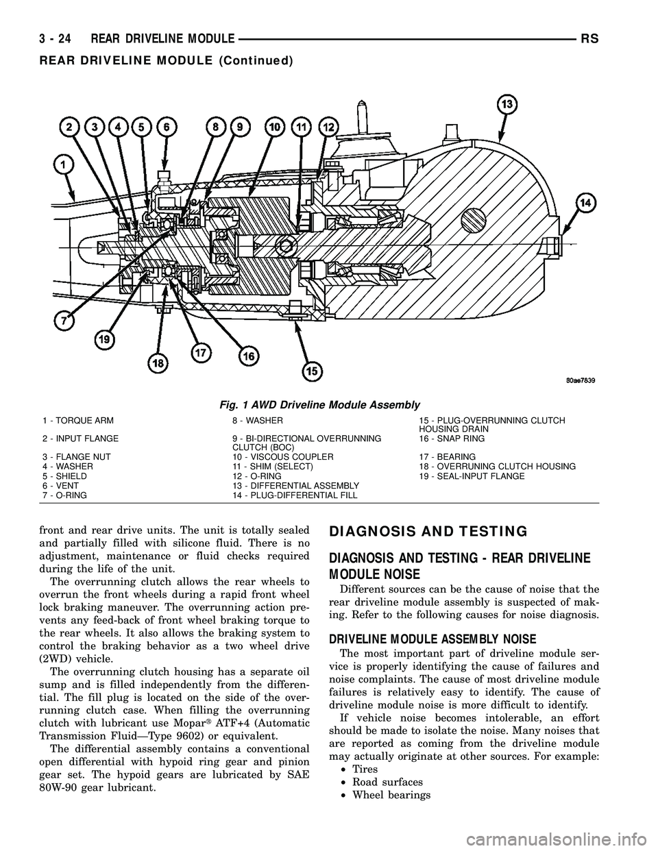
Fig. 1 AWD Driveline Module Assembly
1 - TORQUE ARM 8 - WASHER 15 - PLUG-OVERRUNNING CLUTCH
HOUSING DRAIN
2 - INPUT FLANGE 9 - BI-DIRECTIONAL OVERRUNNING
CLUTCH (BOC)16 - SNAP RING
3 - FLANGE NUT 10 - VISCOUS COUPLER 17 - BEARING
4 - WASHER 11 - SHIM (SELECT) 18 - OVERRUNING CLUTCH HOUSING
5 - SHIELD 12 - O-RING 19 - SEAL-INPUT FLANGE
6 - VENT 13 - DIFFERENTIAL ASSEMBLY
7 - O-RING 14 - PLUG-DIFFERENTIAL FILL
3 - 24 REAR DRIVELINE MODULERS
REAR DRIVELINE MODULE (Continued)
Page 125 of 2585
DIAGNOSIS AND TESTING - REAR DRIVELINE
MODULE OPERATION
Driveline module operation requires relatively
straight-forward diagnosis. Refer to the following
chart:
DRIVELINE MODULE DIAGNOSIS CHART
CONDITION POSSIBLE CAUSES CORRECTION
Rear wheels not
overrunning1) Bi-directional overrunning clutch
failure1) Replace overrunning clutch
components as required
No AWD in forward or
reverse directions, propeller
shaft turning1) Bi-directional overrunning clutch
failure1) Replace overrunning clutch
components as required
2) Viscous coupling failure 2) Replace viscous coupling
3) Rear differential failure 3) Replace the rear differential
assembly
No AWD in forward or
reverse directions, propeller
shaft not turning1) Power transfer unit failure. 1) Replace power transfer unit
components as necessary
Vibration at all speeds,
continuous torque transfer1) Mis-matched tires, worn tires on
front axle.1) Replace worn or incorrect
(mis-matched) tires with same
make and size
REMOVAL
(1) Raise vehicle on hoist.
(2) Drain fluid from overrunning clutch housing
and/or differential assembly if necessary.
(3) Remove propeller shaft. (Refer to 3 - DIFFER-
ENTIAL & DRIVELINE/PROPELLER SHAFT -
REMOVAL)
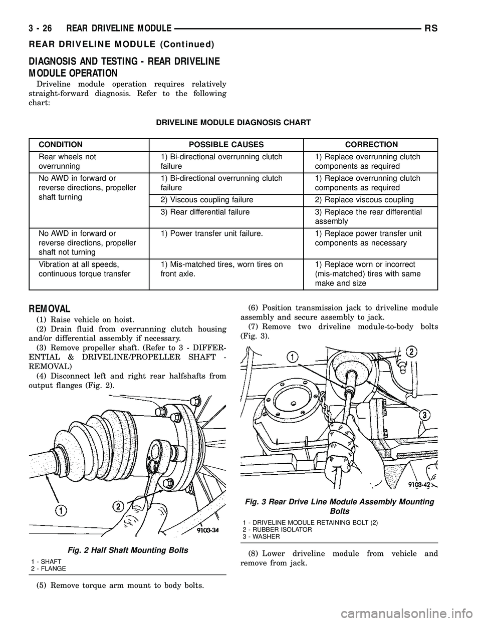
(4) Disconnect left and right rear halfshafts from
output flanges (Fig. 2).
(5) Remove torque arm mount to body bolts.(6) Position transmission jack to driveline module
assembly and secure assembly to jack.
(7) Remove two driveline module-to-body bolts
(Fig. 3).
(8) Lower driveline module from vehicle and
remove from jack.
Fig. 2 Half Shaft Mounting Bolts
1 - SHAFT
2 - FLANGE
Fig. 3 Rear Drive Line Module Assembly Mounting
Bolts
1 - DRIVELINE MODULE RETAINING BOLT (2)
2 - RUBBER ISOLATOR
3 - WASHER
3 - 26 REAR DRIVELINE MODULERS
REAR DRIVELINE MODULE (Continued)
Page 133 of 2585
SPECIFICATIONS - REAR DRIVELINE MODULE
TORQUE SPECIFICATIONS
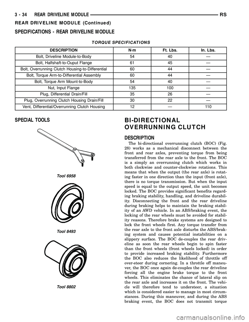
DESCRIPTION N´m Ft. Lbs. In. Lbs.
Bolt, Driveline Module-to-Body 54 40 Ð
Bolt, Halfshaft-to-Ouput Flange 61 45 Ð
Bolt, Overrunning Clutch Housing-to-Differential 60 44 Ð
Bolt, Torque Arm-to-Differential Assembly 60 44 Ð
Bolt, Torque Arm Mount-to-Body 54 40 Ð
Nut, Input Flange 135 100 Ð
Plug, Differential Drain/Fill 35 26 Ð
Plug, Overrunning Clutch Housing Drain/Fill 30 22 Ð
Vent, Differential/Overrunning Clutch Housing 12 Ð 110
SPECIAL TOOLSBI-DIRECTIONAL
OVERRUNNING CLUTCH
DESCRIPTION
The bi-directional overrunning clutch (BOC) (Fig.
28) works as a mechanical disconnect between the
front and rear axles, preventing torque from being
transferred from the rear axle to the front. The BOC
is a simply an overrunning clutch which works in
both clockwise and counter-clockwise rotations. This
means that when the output (the rear axle) is rotat-
ing faster in one direction than the input (front axle),
there is no torque transmission. But when the input
speed is equal to the output speed, the unit becomes
locked. The BOC provides significant benefits regard-
ing braking stability, handling, and driveline durabil-
ity. Disconnecting the front and the rear driveline
during braking helps to maintain the braking stabil-
ity of an AWD vehicle. In an ABS/braking event, the
locking of the rear wheels must be avoided for stabil-
ity reasons. Therefore brake systems are designed to
lock the front wheels first. Any torque transfer from
the rear axle to the front axle disturbs the ABS/brak-
ing system and causes potential instabilities on a
slippery surface. The BOC de-couples the rear driv-
eline as soon the rear wheels begin to spin faster
than the front wheels (front wheels locked) in order
to provide increased braking stability. Furthermore
the BOC also reduces the likelihood of throttle off
over-steer during cornering. In a throttle off maneu-
ver, the BOC once again de-couples the rear driveline
forcing all the engine brake torque to the front
wheels. This eliminates the chance of lateral slip on
the rear axle and increases it on the front. The vehi-
cle will therefore tend to understeer, a situation
which is considered easier to manage in most circum-
stances. During this maneuver, and during the ABS
braking event, the BOC does not transmit torque
Tool 6958
Tool 8493
Tool 8802
3 - 34 REAR DRIVELINE MODULERS
REAR DRIVELINE MODULE (Continued)
Page 139 of 2585
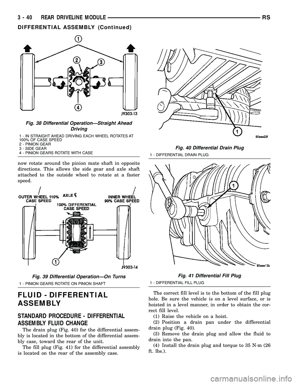
now rotate around the pinion mate shaft in opposite
directions. This allows the side gear and axle shaft
attached to the outside wheel to rotate at a faster
speed.
FLUID - DIFFERENTIAL
ASSEMBLY
STANDARD PROCEDURE - DIFFERENTIAL
ASSEMBLY FLUID CHANGE
The drain plug (Fig. 40) for the differential assem-
bly is located in the bottom of the differential assem-
bly case, toward the rear of the unit.
The fill plug (Fig. 41) for the differential assembly
is located on the rear of the assembly case.The correct fill level is to the bottom of the fill plug
hole. Be sure the vehicle is on a level surface, or is
hoisted in a level manner, in order to obtain the cor-
rect fill level.
(1) Raise the vehicle on a hoist.
(2) Position a drain pan under the differential
drain plug (Fig. 40).
(3) Remove the drain plug and allow the fluid to
drain into the pan.
(4) Install the drain plug and torque to 35 N´m (26
ft. lbs.).
Fig. 38 Differential OperationÐStraight Ahead
Driving
1 - IN STRAIGHT AHEAD DRIVING EACH WHEEL ROTATES AT
100% OF CASE SPEED
2 - PINION GEAR
3 - SIDE GEAR
4 - PINION GEARS ROTATE WITH CASE
Fig. 39 Differential OperationÐOn Turns
1 - PINION GEARS ROTATE ON PINION SHAFT
Fig. 40 Differential Drain Plug
1 - DIFFERENTIAL DRAIN PLUG
Fig. 41 Differential Fill Plug
1 - DIFFERENTIAL FILL PLUG
3 - 40 REAR DRIVELINE MODULERS
DIFFERENTIAL ASSEMBLY (Continued)
Page 140 of 2585
(5) Re-position the drain pan under the differential
fill plug.
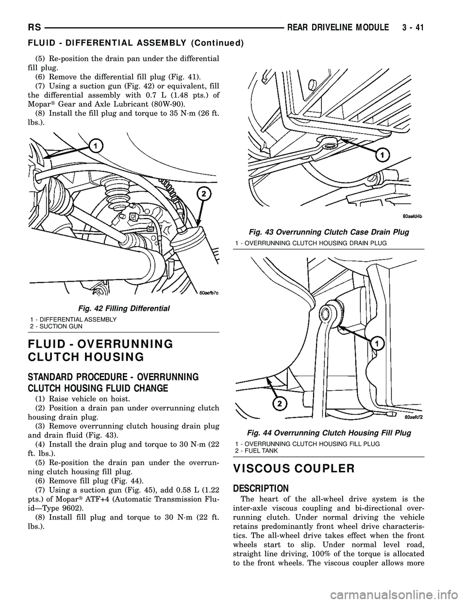
(6) Remove the differential fill plug (Fig. 41).
(7) Using a suction gun (Fig. 42) or equivalent, fill
the differential assembly with 0.7 L (1.48 pts.) of
MopartGear and Axle Lubricant (80W-90).
(8) Install the fill plug and torque to 35 N´m (26 ft.
lbs.).
FLUID - OVERRUNNING
CLUTCH HOUSING
STANDARD PROCEDURE - OVERRUNNING
CLUTCH HOUSING FLUID CHANGE
(1) Raise vehicle on hoist.
(2) Position a drain pan under overrunning clutch
housing drain plug.
(3) Remove overrunning clutch housing drain plug
and drain fluid (Fig. 43).
(4) Install the drain plug and torque to 30 N´m (22
ft. lbs.).
(5) Re-position the drain pan under the overrun-
ning clutch housing fill plug.
(6) Remove fill plug (Fig. 44).
(7) Using a suction gun (Fig. 45), add 0.58 L (1.22
pts.) of MopartATF+4 (Automatic Transmission Flu-
idÐType 9602).
(8) Install fill plug and torque to 30 N´m (22 ft.
lbs.).
VISCOUS COUPLER
DESCRIPTION
The heart of the all-wheel drive system is the
inter-axle viscous coupling and bi-directional over-
running clutch. Under normal driving the vehicle
retains predominantly front wheel drive characteris-
tics. The all-wheel drive takes effect when the front
wheels start to slip. Under normal level road,
straight line driving, 100% of the torque is allocated
to the front wheels. The viscous coupler allows more
Fig. 42 Filling Differential
1 - DIFFERENTIAL ASSEMBLY
2 - SUCTION GUN
Fig. 43 Overrunning Clutch Case Drain Plug
1 - OVERRUNNING CLUTCH HOUSING DRAIN PLUG
Fig. 44 Overrunning Clutch Housing Fill Plug
1 - OVERRUNNING CLUTCH HOUSING FILL PLUG
2 - FUEL TANK
RSREAR DRIVELINE MODULE3-41
FLUID - DIFFERENTIAL ASSEMBLY (Continued)
Page 171 of 2585
DISC BRAKE CALIPER -
FRONT
REMOVAL
REMOVAL - FRONT DISC BRAKE CALIPER
(DISC/DISC BRAKES)
(1) Depress the brake pedal past its first inch of
travel and hold it in this position using a brake pedal
depressor (holding) tool. This is done to isolate the
master cylinder from the brake hydraulic system dis-
allowing the brake fluid to completely drain out of
the brake fluid reservoir.
(2) Raise the vehicle. (Refer to LUBRICATION &
MAINTENANCE/HOISTING - STANDARD PROCE-
DURE).
(3) Remove front wheel and tire assembly.
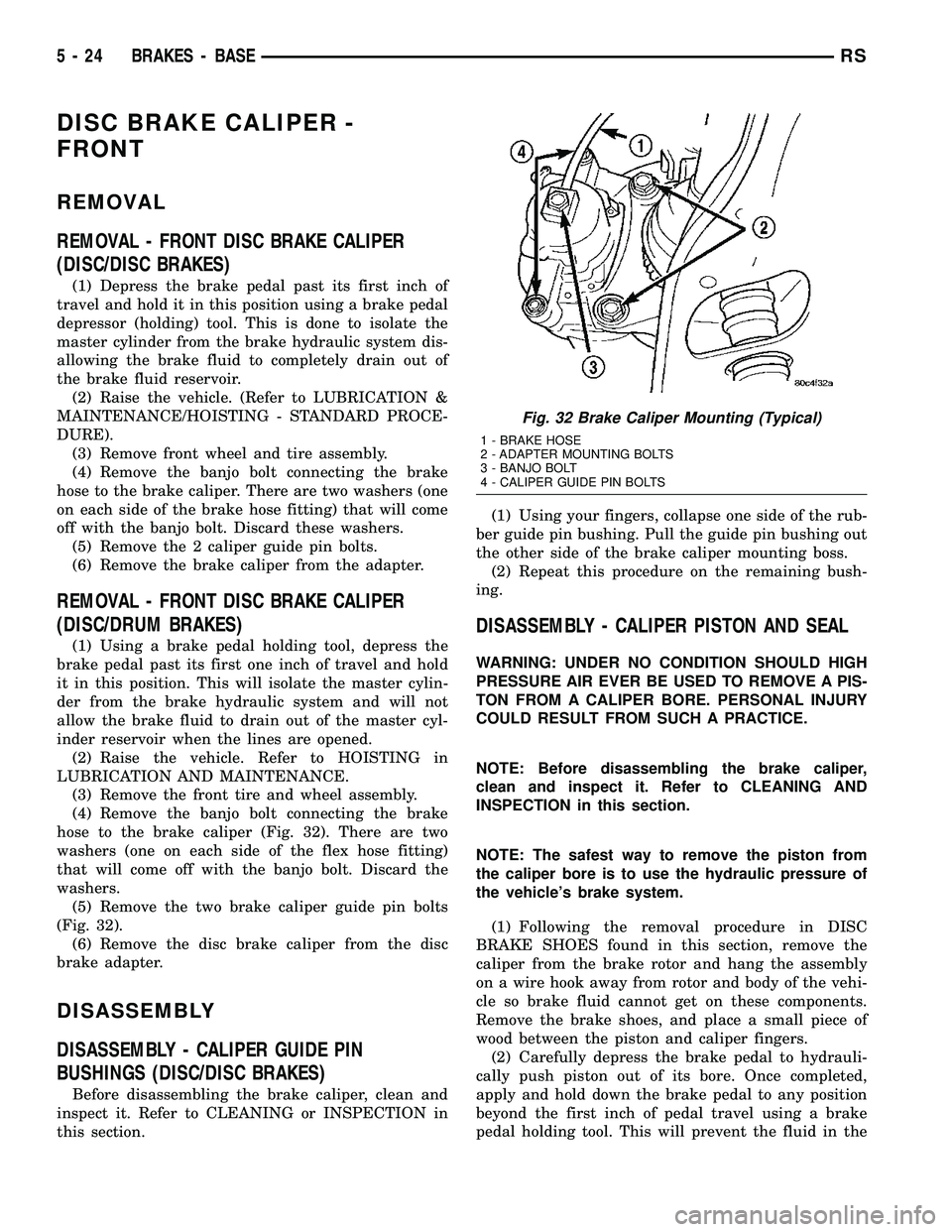
(4) Remove the banjo bolt connecting the brake
hose to the brake caliper. There are two washers (one
on each side of the brake hose fitting) that will come
off with the banjo bolt. Discard these washers.
(5) Remove the 2 caliper guide pin bolts.
(6) Remove the brake caliper from the adapter.
REMOVAL - FRONT DISC BRAKE CALIPER
(DISC/DRUM BRAKES)
(1) Using a brake pedal holding tool, depress the
brake pedal past its first one inch of travel and hold
it in this position. This will isolate the master cylin-
der from the brake hydraulic system and will not
allow the brake fluid to drain out of the master cyl-
inder reservoir when the lines are opened.
(2) Raise the vehicle. Refer to HOISTING in
LUBRICATION AND MAINTENANCE.
(3) Remove the front tire and wheel assembly.
(4) Remove the banjo bolt connecting the brake
hose to the brake caliper (Fig. 32). There are two
washers (one on each side of the flex hose fitting)
that will come off with the banjo bolt. Discard the
washers.
(5) Remove the two brake caliper guide pin bolts
(Fig. 32).
(6) Remove the disc brake caliper from the disc
brake adapter.
DISASSEMBLY
DISASSEMBLY - CALIPER GUIDE PIN
BUSHINGS (DISC/DISC BRAKES)
Before disassembling the brake caliper, clean and
inspect it. Refer to CLEANING or INSPECTION in
this section.(1) Using your fingers, collapse one side of the rub-
ber guide pin bushing. Pull the guide pin bushing out
the other side of the brake caliper mounting boss.
(2) Repeat this procedure on the remaining bush-
ing.
DISASSEMBLY - CALIPER PISTON AND SEAL
WARNING: UNDER NO CONDITION SHOULD HIGH
PRESSURE AIR EVER BE USED TO REMOVE A PIS-
TON FROM A CALIPER BORE. PERSONAL INJURY
COULD RESULT FROM SUCH A PRACTICE.
NOTE: Before disassembling the brake caliper,
clean and inspect it. Refer to CLEANING AND
INSPECTION in this section.
NOTE: The safest way to remove the piston from
the caliper bore is to use the hydraulic pressure of
the vehicle's brake system.
(1) Following the removal procedure in DISC
BRAKE SHOES found in this section, remove the
caliper from the brake rotor and hang the assembly
on a wire hook away from rotor and body of the vehi-
cle so brake fluid cannot get on these components.
Remove the brake shoes, and place a small piece of
wood between the piston and caliper fingers.
(2) Carefully depress the brake pedal to hydrauli-
cally push piston out of its bore. Once completed,
apply and hold down the brake pedal to any position
beyond the first inch of pedal travel using a brake
pedal holding tool. This will prevent the fluid in the
Fig. 32 Brake Caliper Mounting (Typical)
1 - BRAKE HOSE
2 - ADAPTER MOUNTING BOLTS
3 - BANJO BOLT
4 - CALIPER GUIDE PIN BOLTS
5 - 24 BRAKES - BASERS