2004 DODGE TOWN AND COUNTRY child restraint
[x] Cancel search: child restraintPage 656 of 2585
RESTRAINTS
TABLE OF CONTENTS
page page
RESTRAINTS
DESCRIPTION..........................2
OPERATION............................2
WARNING.............................2
DIAGNOSIS AND TESTING - AIRBAG
SYSTEM.............................2
STANDARD PROCEDURE
STANDARD PROCEDURE - HANDLING
AIRBAGS.............................3
STANDARD PROCEDURE - SERVICE
AFTER AN AIRBAG DEPLOYMENT.........3
CHILD RESTRAINT ANCHOR
DESCRIPTION..........................4
OPERATION............................4
CLOCK SPRING
DESCRIPTION..........................4
OPERATION............................4
STANDARD PROCEDURE - CLOCK SPRING
CENTERING..........................5
REMOVAL.............................5
INSTALLATION..........................5
DRIVER AIRBAG
DESCRIPTION..........................6
OPERATION............................6
REMOVAL.............................6
INSTALLATION..........................7
DRIVER AIRBAG TRIM COVER
REMOVAL.............................7
INSTALLATION..........................7
OCCUPANT RESTRAINT CONTROLLER
DESCRIPTION..........................8
OPERATION............................8
REMOVAL.............................8
INSTALLATION..........................8
PASSENGER AIRBAG
DESCRIPTION..........................8
OPERATION............................9
REMOVAL.............................9
INSTALLATION.........................10
SEAT AIRBAG
DESCRIPTION.........................11
OPERATION...........................11
SEAT BELT BUCKLE - FRONT INBOARD
REMOVAL.............................12
INSTALLATION.........................12SEAT BELT BUCKLE - FIRST ROW INBOARD -
QUAD BUCKET
REMOVAL.............................12
INSTALLATION.........................12
SEAT BELT BUCKLE - FIRST ROW - BENCH
REMOVAL.............................13
INSTALLATION.........................13
SEAT BELT BUCKLE - SECOND ROW
INBOARD - 50/50 BENCH
REMOVAL.............................13
INSTALLATION.........................13
SEAT BELT HEIGHT ADJUSTER-BOR
C-PILLAR
REMOVAL.............................13
INSTALLATION.........................13
SEAT BELT HEIGHT ADJUSTER KNOB
REMOVAL.............................14
INSTALLATION.........................14
SEAT BELT & RETRACTOR - OUTBOARD -
FRONT
REMOVAL.............................14
INSTALLATION.........................14
SEAT BELT & RETRACTOR - FIRST ROW -
OUTBOARD
REMOVAL.............................14
INSTALLATION.........................14
SEAT BELT BUCKLE - SECOND ROW - THREE
PASSENGER BENCH
REMOVAL.............................15
INSTALLATION.........................15
SEAT BELT & RETRACTOR - SECOND ROW -
RIGHT OUTBOARD
REMOVAL.............................15
INSTALLATION.........................15
SEAT BELT & RETRACTOR - SECOND ROW -
RIGHT OUTBOARD WITH REAR HVAC - LWB
REMOVAL.............................16
INSTALLATION.........................16
SEAT BELT & RETRACTOR - SECOND ROW -
LEFT OUTBOARD
REMOVAL.............................17
INSTALLATION.........................17
SEAT BELT TENSIONER
DESCRIPTION.........................17
OPERATION...........................17
RSRESTRAINTS8O-1
Page 657 of 2585
RESTRAINTS
DESCRIPTION
This vehicle is equipped with a Frontal Impact Air-
bag System, which utilizes the driver/passenger air-
bags and seatbelt pretensioners. This system is
designed to protect occupants in the event of a front
impact collision. These airbags and seatbelt preten-
sioners are all serviceable parts. If these pyrotechnics
are deployed or defective, they must be replaced, as
well as the Occupant Restraint Controller (ORC)
must be diagnosed following procedures outlined in
the service/diagnostic manuals.
Vehicles equipped with the Side Impact Airbag
System, the seat back assembly must be replaced, as
well as the Side Impact Airbag Control Module
(SIACM) must be diagnosed following procedures
outlined in the service/diagnostic manuals.
OPERATION
The Occupant Restraint Controller (ORC) controls
the driver/passenger airbags and seat belt tensioners.
If the ORC determines that the impact is severe
enough, the driver/passenger/side airbags and seat
belt tensioners will deploy. Once a deployment
occurs, these devices, and all damaged parts must be
replaced, as well as the ORC must be diagnosed fol-
lowing procedures outlined in the service/diagnostic
manuals.
The Side Impact Airbag Control Module (SIACM),
the seat back assemblies and all damaged parts must
be replaced, as well as the SIACM must be diagnosed
following procedures outlined in the service/diagnos-
tic manuals.
WARNING
WARNING: THIS SYSTEM IS A SENSITIVE, COM-
PLEX ELECTRO±MECHANICAL UNIT. DISCONNECT
AND ISOLATE THE BATTERY NEGATIVE CABLE
BEFORE BEGINNING AIRBAG SYSTEM COMPO-
NENT REMOVAL OR INSTALLATION PROCEDURES.
THIS WILL DISABLE THE AIRBAG SYSTEM. FAIL-
URE TO DISCONNECT THE BATTERY COULD
RESULT IN ACCIDENTAL AIRBAG DEPLOYMENT,
PERSONAL INJURY, OR DEATH.
ALLOW SYSTEM CAPACITOR TO DISCHARGE FOR
TWO MINUTES BEFORE REMOVING AIRBAG COM-
PONENTS.
DO NOT PLACE AN INTACT UNDEPLOYED AIRBAG
FACE DOWN ON A SOLID SURFACE, THE AIRBAG
WILL PROPEL INTO THE AIR IF ACCIDENTALLY
DEPLOYED AND COULD RESULT IN PERSONAL
INJURY. WHEN CARRYING OR HANDLING AN
UNDEPLOYED AIRBAG MODULE, THE TRIM SIDE
OF THE AIRBAG SHOULD BE POINTING AWAYFROM THE BODY TO MINIMIZE POSSIBILITY OF
INJURY IF ACCIDENTAL DEPLOYMENT OCCURS.
REPLACE AIRBAG SYSTEM COMPONENTS WITH
MOPARTREPLACEMENT PARTS. SUBSTITUTE
PARTS MAY APPEAR INTERCHANGEABLE, BUT
INTERNAL DIFFERENCES MAY RESULT IN INFE-
RIOR OCCUPANT PROTECTION.
WEAR SAFETY GLASSES, RUBBER GLOVES, AND
LONG SLEEVED CLOTHING WHEN CLEANING
POWDER RESIDUE FROM VEHICLE AFTER AIRBAG
DEPLOYMENT. SODIUM HYDROXIDE POWDER
RESIDUE EMITTED FROM A DEPLOYED AIRBAG
CAN CAUSE SKIN IRRITATION. FLUSH AFFECTED
AREA WITH COOL WATER IF IRRITATION IS EXPE-
RIENCED. IF NASAL OR THROAT IRRITATION IS
EXPERIENCED, EXIT THE VEHICLE FOR FRESH AIR
UNTIL THE IRRITATION CEASES. IF IRRITATION
CONTINUES, SEE A PHYSICIAN.
DO NOT USE A REPLACEMENT AIRBAG THAT IS
NOT IN THE ORIGINAL PACKAGING, IMPROPER
DEPLOYMENT, PERSONAL INJURY, OR DEATH CAN
RESULT.
THE FACTORY INSTALLED FASTENERS, SCREWS
AND BOLTS USED TO FASTEN AIRBAG COMPO-
NENTS HAVE A SPECIAL COATING AND ARE SPE-
CIFICALLY DESIGNED FOR THE AIRBAG SYSTEM.
DO NOT USE SUBSTITUTE FASTENERS, USE ONLY
ORIGINAL EQUIPMENT FASTENERS LISTED IN THE
PARTS CATALOG WHEN FASTENER REPLACE-
MENT IS REQUIRED.
CAUTION:
Deployed and Nondeployed Air Bags may or may
not have live pyrotechnic material within the air bag
inflator. Do not dispose of Driver and Passenger
Airbags unless you are sure of complete deploy-
ment. Please refer to the Hazardous Substance
Control System for Proper Disposal. Dispose of
deployed air bags in a manner consistent with
state, provincial, local, and federal regulations.
WARNING: DURING, AND FOLLOWING, ANY CHILD
RESTRAINT ANCHOR SERVICE, DUE TO IMPACT
EVENT OR VEHICLE REPAIR, CAREFULLY INSPECT
ALL MOUNTING HARDWARE, TETHER STRAPS
AND ANCHORS FOR PROPER INSTALLATION,
OPERATION, OR DAMAGE. IF A CHILD RESTRAINT
ANCHOR IS FOUND DAMAGED IN ANY WAY, THE
ANCHOR MUST BE REPLACED OR IT COULD
RESULT IN PERSONAL INJURY OR DEATH.
DIAGNOSIS AND TESTING - AIRBAG SYSTEM
(1) With the battery negative remote cable discon-
nected, connect the DRB IIItscan tool to the Data
Link connector.
8O - 2 RESTRAINTSRS
Page 658 of 2585
(2) Turn the ignition key to the ON position. Exit
vehicle with the scan tool.
(3) After checking that no one is inside the vehicle,
connect the battery negative remote terminal.
(4) Read and record theACTIVEDiagnostic Trou-
ble Code (DTC) data.
(5) Read and record anySTOREDDTC's.
(6) Refer to the proper Body Diagnostic Procedures
manual if any DTC's are found in Step 4 and Step 5.
(7) If the airbag warning lamp either fails to light,
or goes ON and stays ON, there is a system malfunc-
tion. To test the airbag warning lamp (bulb) opera-
tion in the cluster, refer to Electrical, Instrument
Cluster, Diagnosis and Testing - Instrument Cluster.
Refer to the proper Body Diagnostic Procedures man-
ual for any other system problems.
STANDARD PROCEDURE
STANDARD PROCEDURE - HANDLING
AIRBAGS
DEPLOYED AIRBAG
The vehicle interior may contain a very small
amount of sodium hydroxide powder, a by-product of
airbag deployment. Sodium hydroxide powder can
irritate the skin, eyes, nose and throat. Wear safety
glasses, rubber gloves, and long sleeved clothing
when cleaning any of the powder residue from the
vehicle.
If you find that the cleanup is irritating your skin,
run cool water over the affected area. Also, if you
experience nasal or throat irritation, exit the vehicle
for fresh air until the irritation ceases. If irritation
continues, see a physician.
UNDEPLOYED AIRBAG
The airbags must be stored in its original special
container until used for service. At no time should a
source of electricity be permitted near the inflator on
the back of an airbag module. When carrying or han-
dling an undeployed airbag module, the trim side of
the airbag should be pointing away from the body to
minimize possibility of injury if accidental deploy-
ment occurs. Do not place undeployed airbag face
down on a solid surface, the airbag will propel into
the air if accidental deployment occurs.
STANDARD PROCEDURE - SERVICE AFTER AN
AIRBAG DEPLOYMENT
DRIVER AIRBAG
After a Driver Airbag has been deployed due to a
collision, the followingMUSTbe replaced:
²Driver Airbag²Clock Spring Assembly
²Steering Wheel
²Complete Steering Column Assembly w/Lower
Steering Column Coupler
All other airbag and vehicle components should be
closely inspected following any airbag deployment,
and should be replaced when visible damage is
incurred.
PASSENGER AIRBAG
After a Passenger Airbag has been deployed due to
a collision. the followingMUSTbe replaced:
²Passenger Airbag
²Instrument Panel and Pad Assembly
All other airbag and vehicle components should be
closely inspected following any airbag deployment,
and should be replaced when visible damage is
incurred.
SEAT AIRBAG
After a Seat Airbag has been deployed due to a col-
lision. the followingMUSTbe replaced:
²Complete Seat Back Assembly
All other airbag and vehicle components should be
closely inspected following any airbag deployment,
and should be replaced when visible damage is
incurred.
SEAT BELTS AND TENSIONERS
After a frontal impact where an airbag has been
deployed due to a collision. the followingMUSTbe
replaced:
²Front Seat Belt Buckle (driver and passenger)
with integral Tensioners.
All other seat belts should be closely inspected for
cuts, tears, fraying, or damage in any way following
any frontal impact or airbag deployment. The other
seat belts are to be replaced when visible damage is
incurred. Inspect the Lower Anchors and Tether for
CHildren (LATCH) child restraint anchors for dam-
age after an impact event and replace as needed.
CLEAN UP PROCEDURE
Roll or fold the airbag towards its mounting point
(i.e. instrument panel, steering wheel, or seat back).
Then tape the ripped cover over the deployed airbag
if applicable.
Use a vacuum cleaner to remove any residual pow-
der from the vehicle interior. Work from the outside
in to avoid kneeling or sitting in a contaminated
area. Vacuum the heater and A/C outlets as well (Fig.
1). If the heater or air conditioner was in RECIRC
mode at time of airbag deployment, operate blower
motor on low speed and vacuum powder residue
expelled from the heater and A/C outlets. Multiple
RSRESTRAINTS8O-3
RESTRAINTS (Continued)
Page 659 of 2585
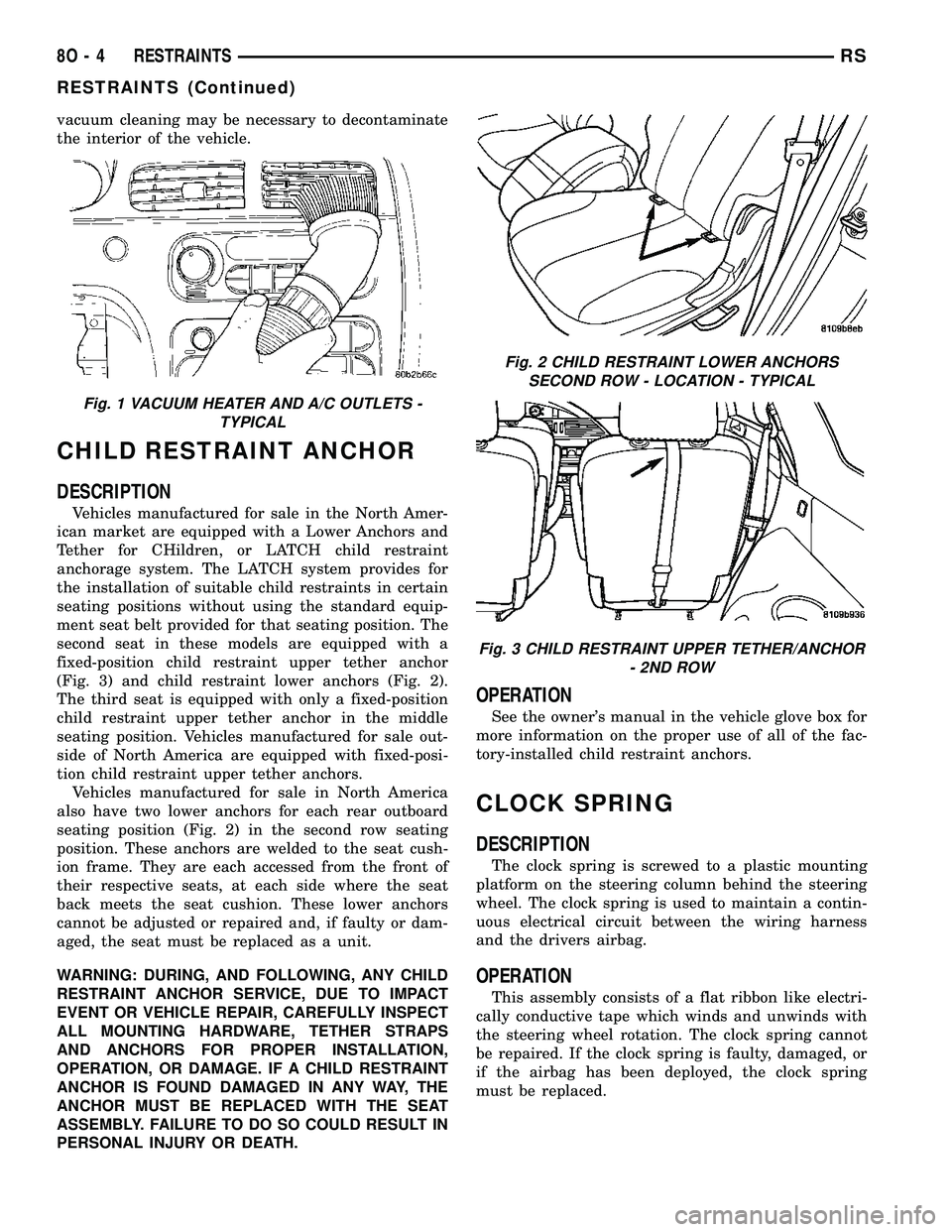
vacuum cleaning may be necessary to decontaminate
the interior of the vehicle.
CHILD RESTRAINT ANCHOR
DESCRIPTION
Vehicles manufactured for sale in the North Amer-
ican market are equipped with a Lower Anchors and
Tether for CHildren, or LATCH child restraint
anchorage system. The LATCH system provides for
the installation of suitable child restraints in certain
seating positions without using the standard equip-
ment seat belt provided for that seating position. The
second seat in these models are equipped with a
fixed-position child restraint upper tether anchor
(Fig. 3) and child restraint lower anchors (Fig. 2).
The third seat is equipped with only a fixed-position
child restraint upper tether anchor in the middle
seating position. Vehicles manufactured for sale out-
side of North America are equipped with fixed-posi-
tion child restraint upper tether anchors.
Vehicles manufactured for sale in North America
also have two lower anchors for each rear outboard
seating position (Fig. 2) in the second row seating
position. These anchors are welded to the seat cush-
ion frame. They are each accessed from the front of
their respective seats, at each side where the seat
back meets the seat cushion. These lower anchors
cannot be adjusted or repaired and, if faulty or dam-
aged, the seat must be replaced as a unit.
WARNING: DURING, AND FOLLOWING, ANY CHILD
RESTRAINT ANCHOR SERVICE, DUE TO IMPACT
EVENT OR VEHICLE REPAIR, CAREFULLY INSPECT
ALL MOUNTING HARDWARE, TETHER STRAPS
AND ANCHORS FOR PROPER INSTALLATION,
OPERATION, OR DAMAGE. IF A CHILD RESTRAINT
ANCHOR IS FOUND DAMAGED IN ANY WAY, THE
ANCHOR MUST BE REPLACED WITH THE SEAT
ASSEMBLY. FAILURE TO DO SO COULD RESULT IN
PERSONAL INJURY OR DEATH.
OPERATION
See the owner's manual in the vehicle glove box for
more information on the proper use of all of the fac-
tory-installed child restraint anchors.
CLOCK SPRING
DESCRIPTION
The clock spring is screwed to a plastic mounting
platform on the steering column behind the steering
wheel. The clock spring is used to maintain a contin-
uous electrical circuit between the wiring harness
and the drivers airbag.
OPERATION
This assembly consists of a flat ribbon like electri-
cally conductive tape which winds and unwinds with
the steering wheel rotation. The clock spring cannot
be repaired. If the clock spring is faulty, damaged, or
if the airbag has been deployed, the clock spring
must be replaced.
Fig. 1 VACUUM HEATER AND A/C OUTLETS -
TYPICAL
Fig. 2 CHILD RESTRAINT LOWER ANCHORS
SECOND ROW - LOCATION - TYPICAL
Fig. 3 CHILD RESTRAINT UPPER TETHER/ANCHOR
- 2ND ROW
8O - 4 RESTRAINTSRS
RESTRAINTS (Continued)
Page 2198 of 2585
BENCH SEAT TRACK
REMOVAL............................104
INSTALLATION........................104
PLASTIC GROCERY BAG RETAINER
REMOVAL............................104
INSTALLATION........................105
UNDER SEAT STORAGE BIN
REMOVAL............................105
INSTALLATION........................105
UNDER SEAT STORAGE BIN GUIDE
REMOVAL............................105
INSTALLATION........................105
UNDER SEAT STORAGE BIN LOCK/LATCH
REMOVAL............................105INSTALLATION........................105
LUMBAR SUPPORT
REMOVAL............................106
INSTALLATION........................106
SEAT RISER LATCH LOCKING LINK
REMOVAL............................106
INSTALLATION........................106
QUAD BUCKET SEAT SIDE SHIELD/
CUPHOLDER - FLAP AND SPRING
ASSEMBLY
REMOVAL............................107
INSTALLATION........................107
CHILD SEAT MODULE, BENCH
SEAT
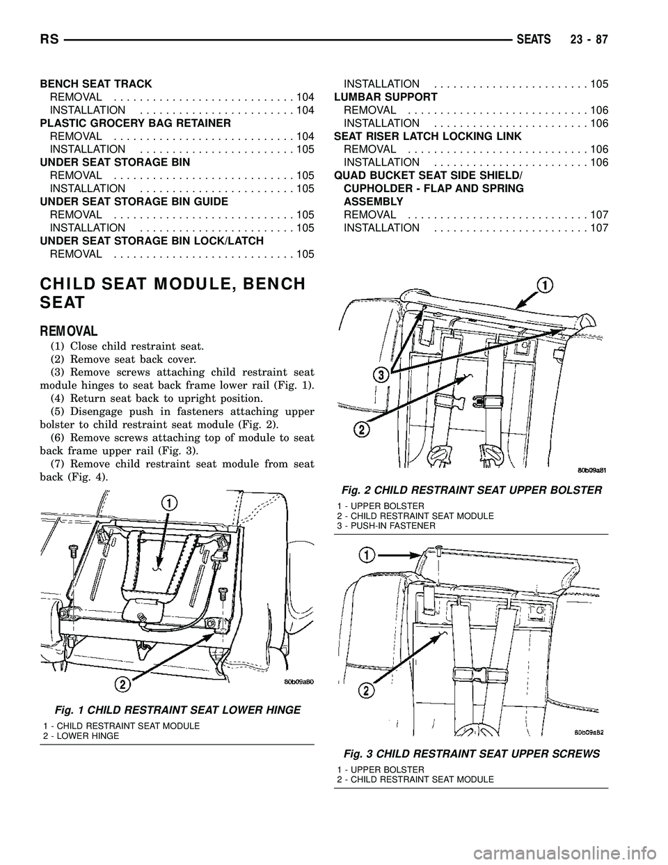
REMOVAL
(1) Close child restraint seat.
(2) Remove seat back cover.
(3) Remove screws attaching child restraint seat
module hinges to seat back frame lower rail (Fig. 1).
(4) Return seat back to upright position.
(5) Disengage push in fasteners attaching upper
bolster to child restraint seat module (Fig. 2).
(6) Remove screws attaching top of module to seat
back frame upper rail (Fig. 3).
(7) Remove child restraint seat module from seat
back (Fig. 4).
Fig. 1 CHILD RESTRAINT SEAT LOWER HINGE
1 - CHILD RESTRAINT SEAT MODULE
2 - LOWER HINGE
Fig. 2 CHILD RESTRAINT SEAT UPPER BOLSTER
1 - UPPER BOLSTER
2 - CHILD RESTRAINT SEAT MODULE
3 - PUSH-IN FASTENER
Fig. 3 CHILD RESTRAINT SEAT UPPER SCREWS
1 - UPPER BOLSTER
2 - CHILD RESTRAINT SEAT MODULE
RSSEATS23-87
Page 2199 of 2585
INSTALLATION
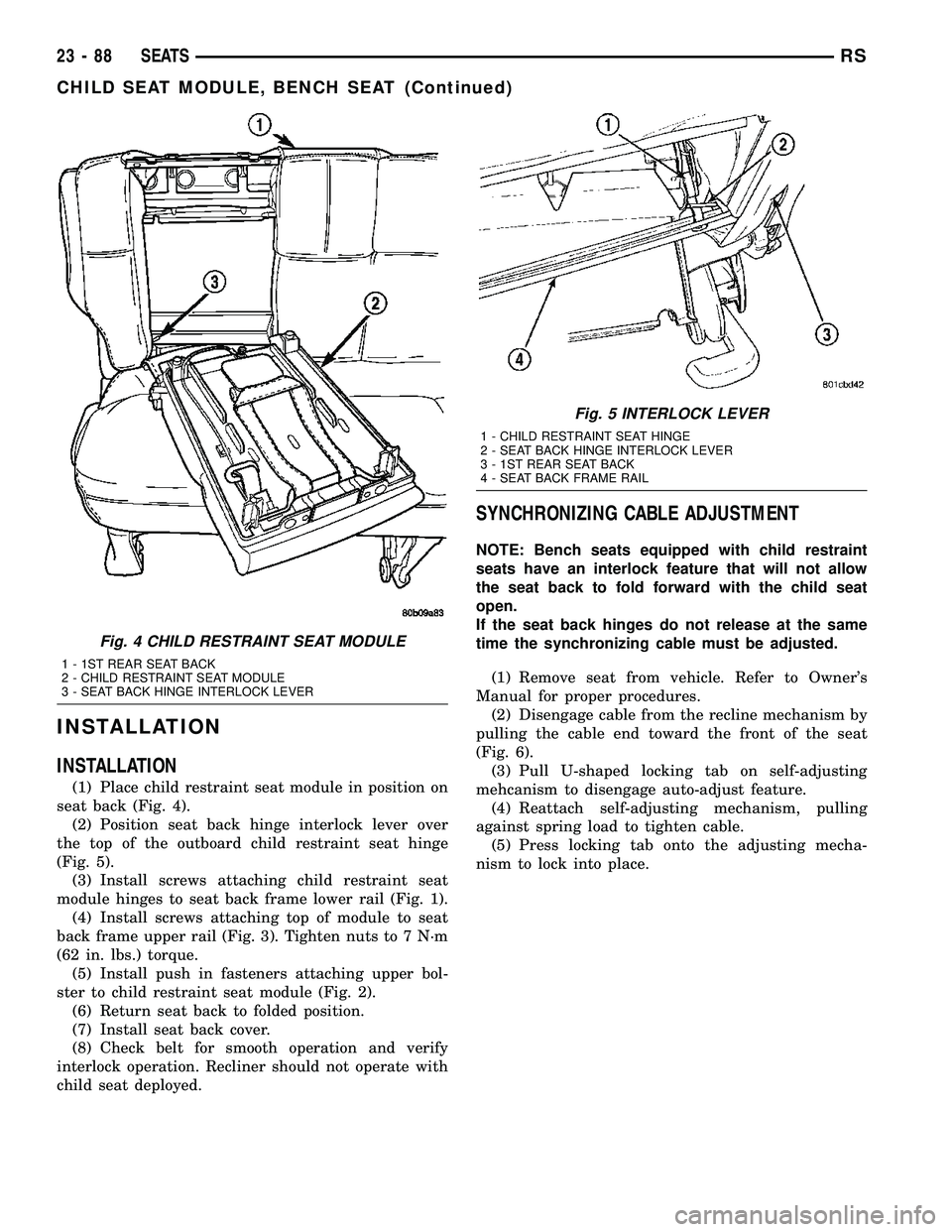
INSTALLATION
(1) Place child restraint seat module in position on
seat back (Fig. 4).
(2) Position seat back hinge interlock lever over
the top of the outboard child restraint seat hinge
(Fig. 5).
(3) Install screws attaching child restraint seat
module hinges to seat back frame lower rail (Fig. 1).
(4) Install screws attaching top of module to seat
back frame upper rail (Fig. 3). Tighten nuts to 7 N´m
(62 in. lbs.) torque.
(5) Install push in fasteners attaching upper bol-
ster to child restraint seat module (Fig. 2).
(6) Return seat back to folded position.
(7) Install seat back cover.
(8) Check belt for smooth operation and verify
interlock operation. Recliner should not operate with
child seat deployed.
SYNCHRONIZING CABLE ADJUSTMENT
NOTE: Bench seats equipped with child restraint
seats have an interlock feature that will not allow
the seat back to fold forward with the child seat
open.
If the seat back hinges do not release at the same
time the synchronizing cable must be adjusted.
(1) Remove seat from vehicle. Refer to Owner's
Manual for proper procedures.
(2) Disengage cable from the recline mechanism by
pulling the cable end toward the front of the seat
(Fig. 6).
(3) Pull U-shaped locking tab on self-adjusting
mehcanism to disengage auto-adjust feature.
(4) Reattach self-adjusting mechanism, pulling
against spring load to tighten cable.
(5) Press locking tab onto the adjusting mecha-
nism to lock into place.
Fig. 4 CHILD RESTRAINT SEAT MODULE
1 - 1ST REAR SEAT BACK
2 - CHILD RESTRAINT SEAT MODULE
3 - SEAT BACK HINGE INTERLOCK LEVER
Fig. 5 INTERLOCK LEVER
1 - CHILD RESTRAINT SEAT HINGE
2 - SEAT BACK HINGE INTERLOCK LEVER
3 - 1ST REAR SEAT BACK
4 - SEAT BACK FRAME RAIL
23 - 88 SEATSRS
CHILD SEAT MODULE, BENCH SEAT (Continued)
Page 2200 of 2585
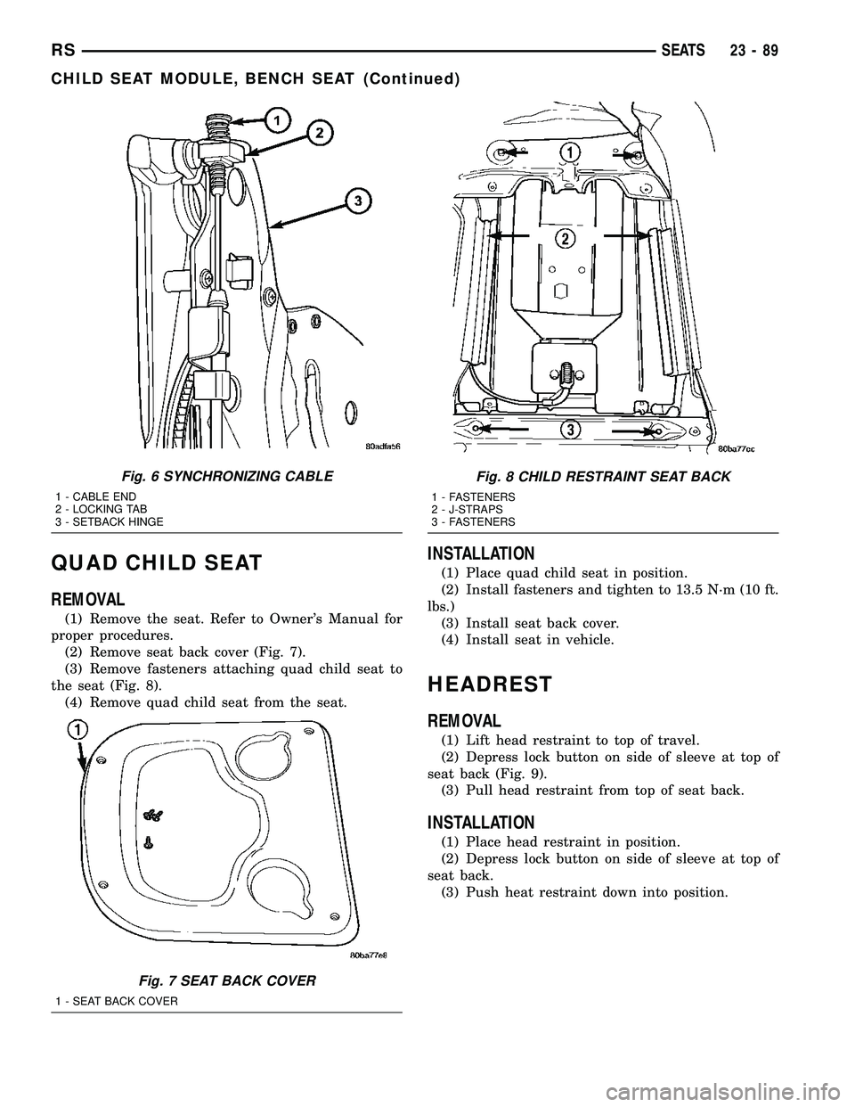
QUAD CHILD SEAT
REMOVAL
(1) Remove the seat. Refer to Owner's Manual for
proper procedures.
(2) Remove seat back cover (Fig. 7).
(3) Remove fasteners attaching quad child seat to
the seat (Fig. 8).
(4) Remove quad child seat from the seat.
INSTALLATION
(1) Place quad child seat in position.
(2) Install fasteners and tighten to 13.5 N´m (10 ft.
lbs.)
(3) Install seat back cover.
(4) Install seat in vehicle.
HEADREST
REMOVAL
(1) Lift head restraint to top of travel.
(2) Depress lock button on side of sleeve at top of
seat back (Fig. 9).
(3) Pull head restraint from top of seat back.
INSTALLATION
(1) Place head restraint in position.
(2) Depress lock button on side of sleeve at top of
seat back.
(3) Push heat restraint down into position.
Fig. 6 SYNCHRONIZING CABLE
1 - CABLE END
2 - LOCKING TAB
3 - SETBACK HINGE
Fig. 7 SEAT BACK COVER
1 - SEAT BACK COVER
Fig. 8 CHILD RESTRAINT SEAT BACK
1 - FASTENERS
2 - J-STRAPS
3 - FASTENERS
RSSEATS23-89
CHILD SEAT MODULE, BENCH SEAT (Continued)
Page 2209 of 2585
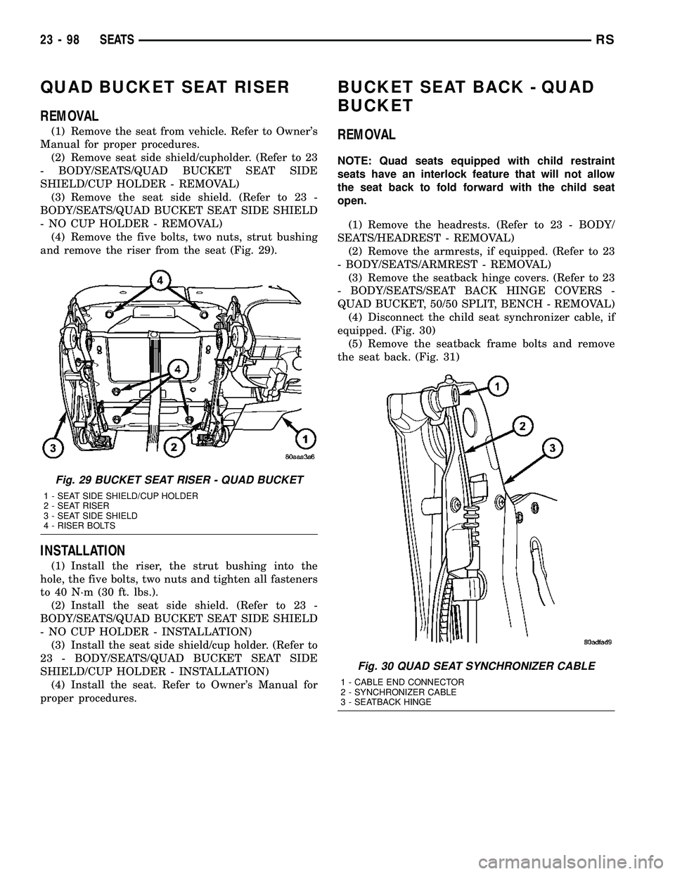
QUAD BUCKET SEAT RISER
REMOVAL
(1) Remove the seat from vehicle. Refer to Owner's
Manual for proper procedures.
(2) Remove seat side shield/cupholder. (Refer to 23
- BODY/SEATS/QUAD BUCKET SEAT SIDE
SHIELD/CUP HOLDER - REMOVAL)
(3) Remove the seat side shield. (Refer to 23 -
BODY/SEATS/QUAD BUCKET SEAT SIDE SHIELD
- NO CUP HOLDER - REMOVAL)
(4) Remove the five bolts, two nuts, strut bushing
and remove the riser from the seat (Fig. 29).
INSTALLATION
(1) Install the riser, the strut bushing into the
hole, the five bolts, two nuts and tighten all fasteners
to 40 N´m (30 ft. lbs.).
(2) Install the seat side shield. (Refer to 23 -
BODY/SEATS/QUAD BUCKET SEAT SIDE SHIELD
- NO CUP HOLDER - INSTALLATION)
(3) Install the seat side shield/cup holder. (Refer to
23 - BODY/SEATS/QUAD BUCKET SEAT SIDE
SHIELD/CUP HOLDER - INSTALLATION)
(4) Install the seat. Refer to Owner's Manual for
proper procedures.
BUCKET SEAT BACK - QUAD
BUCKET
REMOVAL
NOTE: Quad seats equipped with child restraint
seats have an interlock feature that will not allow
the seat back to fold forward with the child seat
open.
(1) Remove the headrests. (Refer to 23 - BODY/
SEATS/HEADREST - REMOVAL)
(2) Remove the armrests, if equipped. (Refer to 23
- BODY/SEATS/ARMREST - REMOVAL)
(3) Remove the seatback hinge covers. (Refer to 23
- BODY/SEATS/SEAT BACK HINGE COVERS -
QUAD BUCKET, 50/50 SPLIT, BENCH - REMOVAL)
(4) Disconnect the child seat synchronizer cable, if
equipped. (Fig. 30)
(5) Remove the seatback frame bolts and remove
the seat back. (Fig. 31)
Fig. 29 BUCKET SEAT RISER - QUAD BUCKET
1 - SEAT SIDE SHIELD/CUP HOLDER
2 - SEAT RISER
3 - SEAT SIDE SHIELD
4 - RISER BOLTS
Fig. 30 QUAD SEAT SYNCHRONIZER CABLE
1 - CABLE END CONNECTOR
2 - SYNCHRONIZER CABLE
3 - SEATBACK HINGE
23 - 98 SEATSRS